We need some gas

With the rudder all finished, it went up in the ceiling with the other finished components to make room on the workbench for the next project.  Fuel tanks are a key part of each build and one that is often dreaded because of the process and mess that it can make.  I’ve read a lot of how-to’s and gotten a lot of advice and feel pretty confident moving into this stage.  I also invested in a few tools that should make the job a little easier, cleaner, and more effective!

First is to prep just like all other steps.  The previous builder of my wing kit started the left fuel tank, getting so far as to seal the ribs and fuel cap flange to the skin.  However, I want to have the upgraded locking caps and wasn’t comfortable with the sealing job that had been done.  So I decided to order replacement parts and start fresh.  I also used the now scrap tank to practice with was helpful.

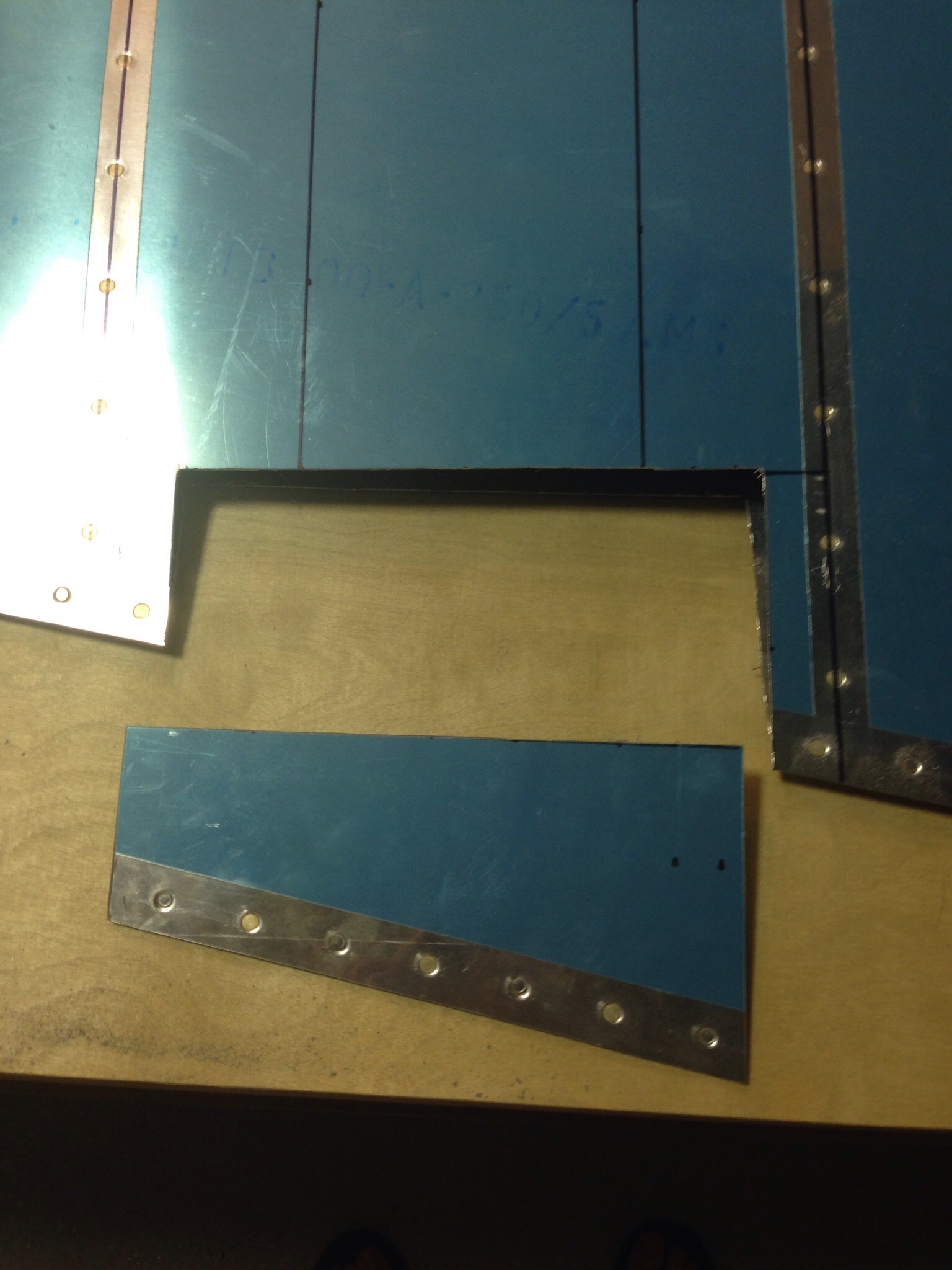
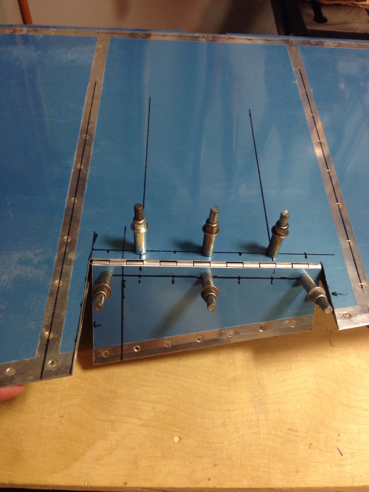
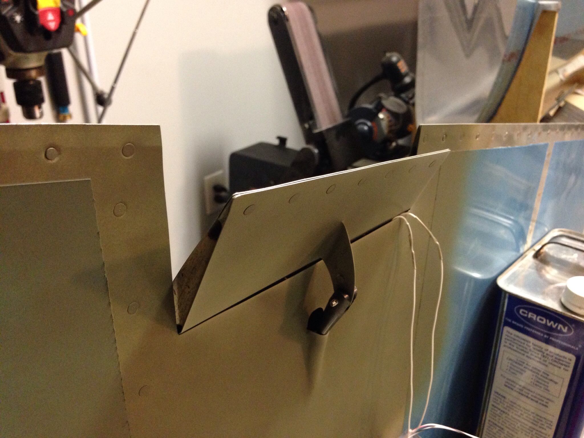
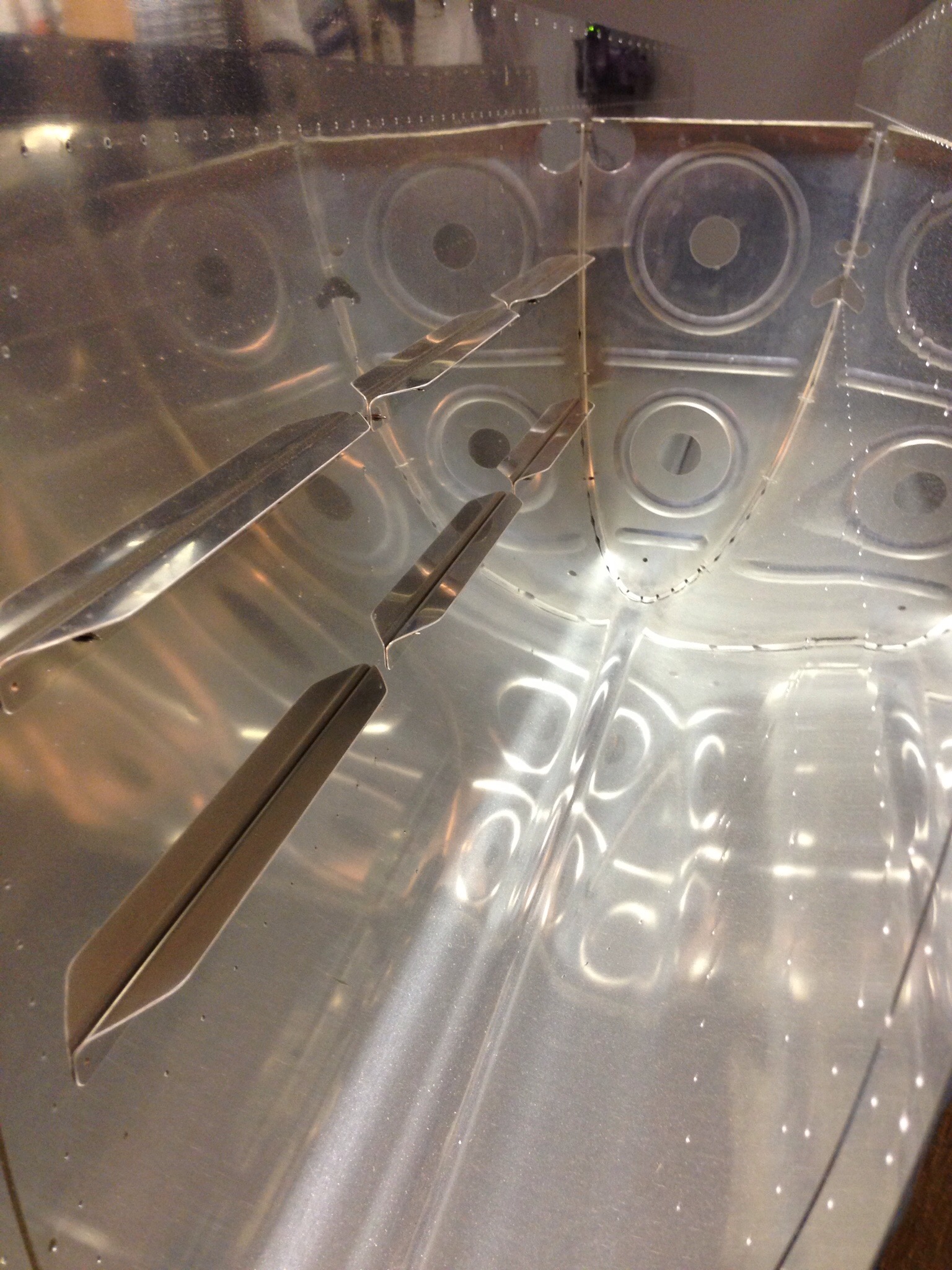
Each tank has 14 stiffners that are cut from a single stick of aluminum similar to most of the j channels.  Those are cut, shaped, and deburred then match drilled to the skins.  The ribs are also finessed into the skins, especially the pointy part that doesn’t seem to fit well without a little encouragement with the pliers.  I was surprised at how difficult it was to get all the ribs lined up for match drilling.

IMG_0240.JPG

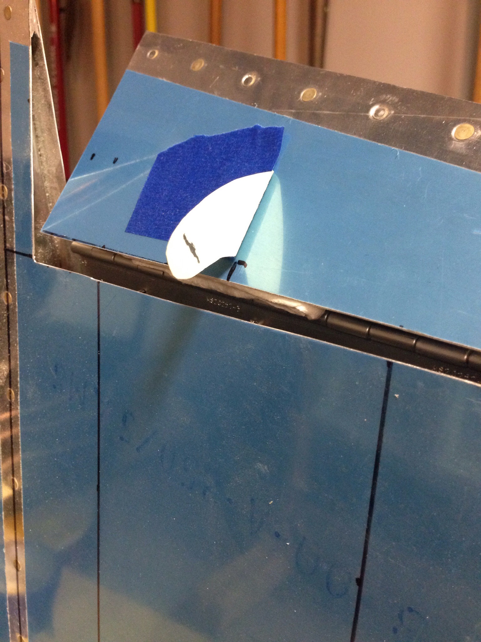
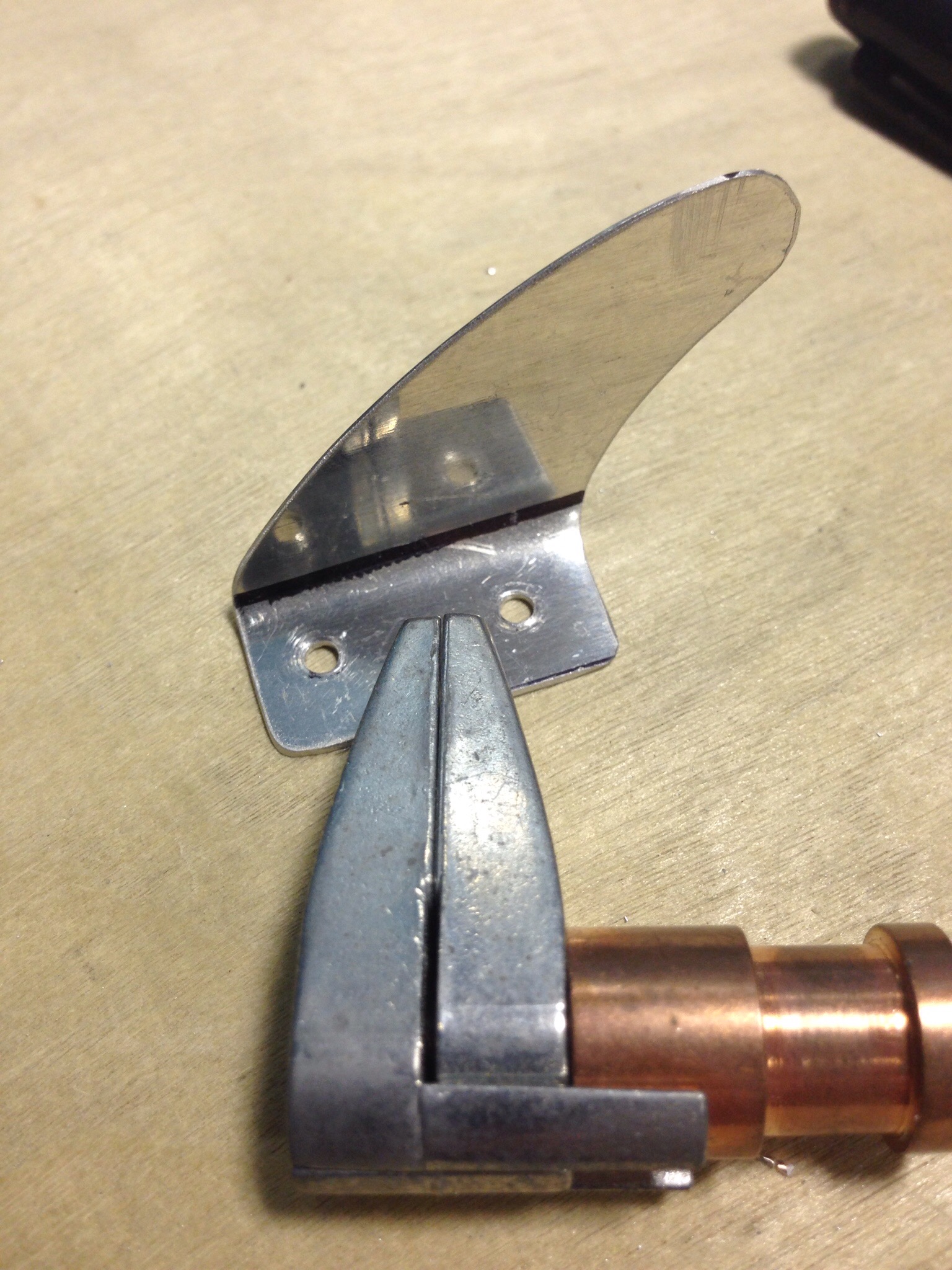
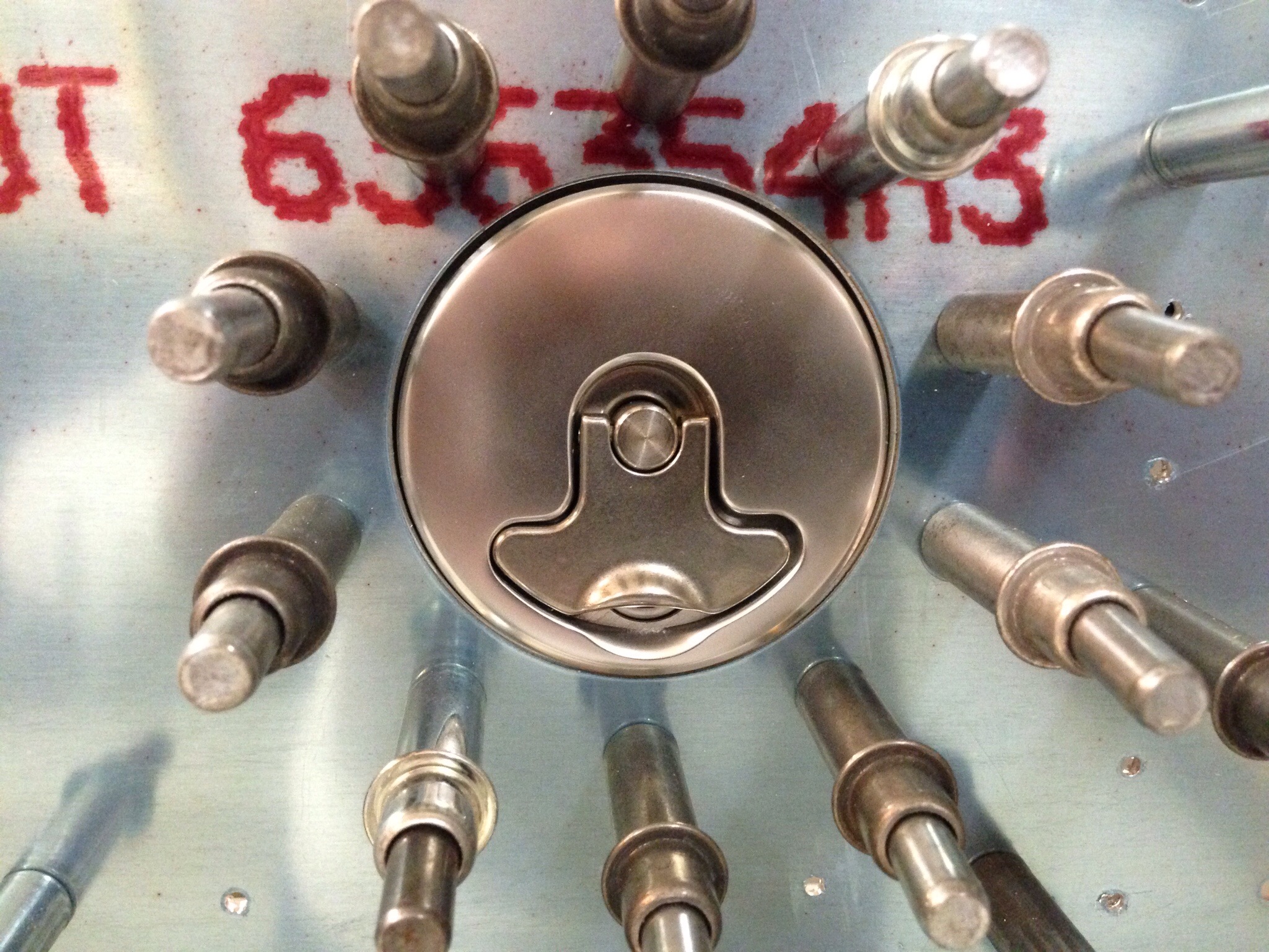
The fuel cap flange is contoured to match the skin.  I used some of the double sided tape for trailing edges to hold it in place for match drilling.  One thing to note is that the locking cap looks a lot better and fits a lot better than the stock Van’s unit.  Well worth the extra money for me.

IMG_0311.JPG

The attache zee’s were next, having been match drilled to the tank spar and having nut plates installed.  These will be primed as will the exterior of the tank ribs.  Nothing inside is primed, as the fuel is corrosive to all but the mightiest of paints.

IMG_0313.JPG

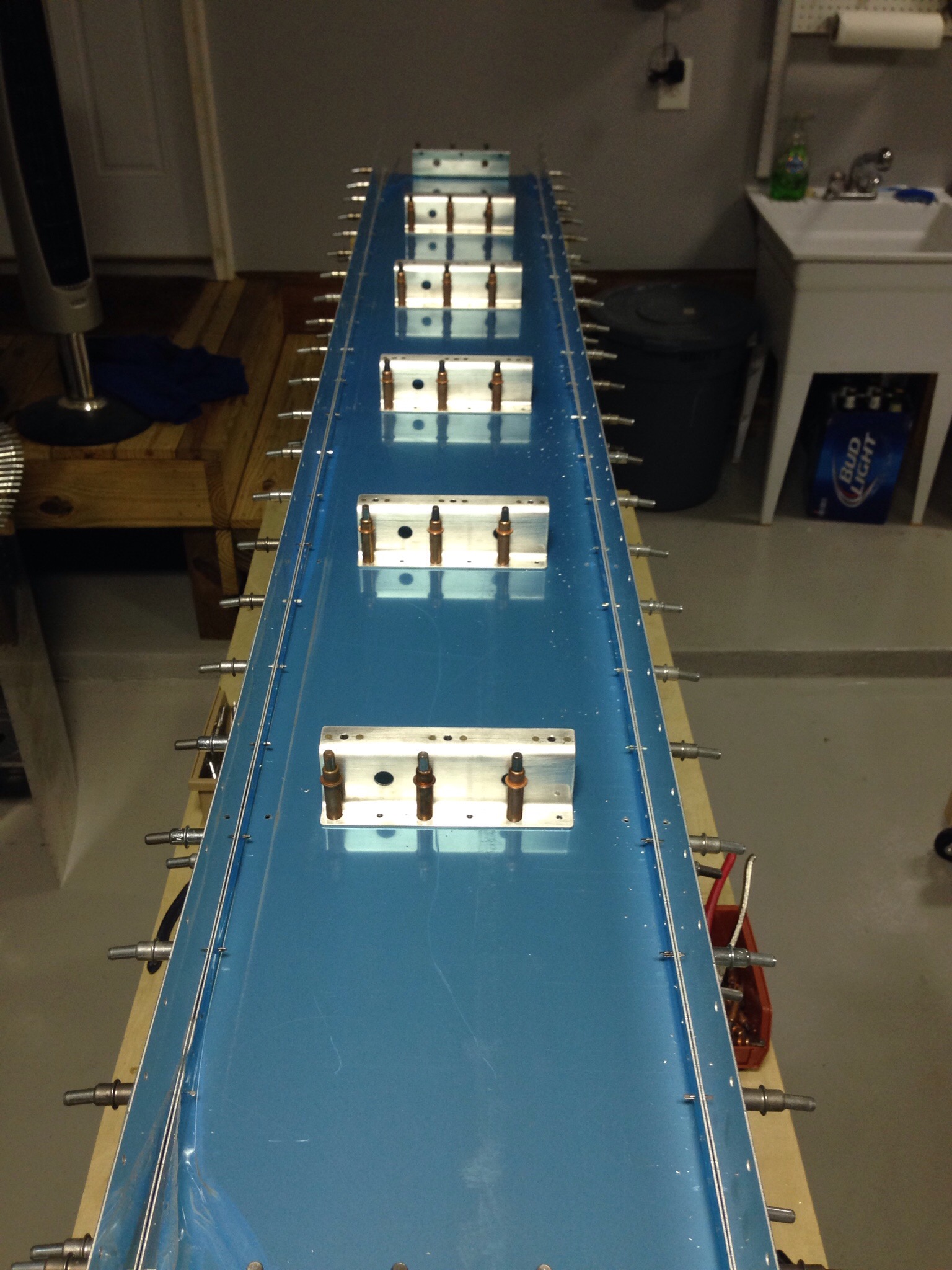
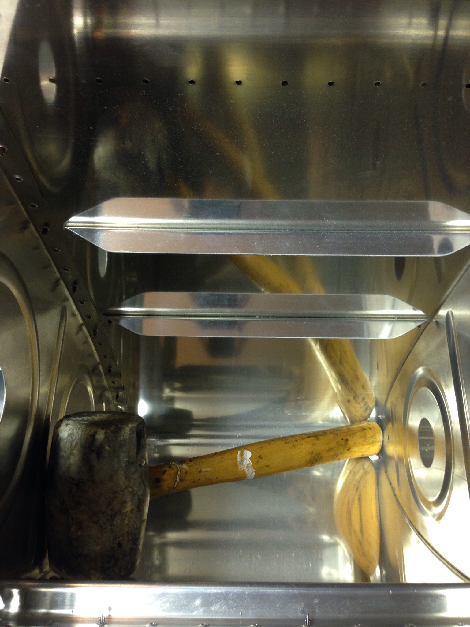
One piece of advice to heed, make sure nothing is in the tanks that doesn’t belong!  I had used my rubber mallet to tap some pieces into alignment.  I found it after enclosing the tank with clecos to match drill.  I looked all over the garage for that thing!

IMG_0324.JPG

Just a little trim

With the rudder complete according to the plans, it’s time for me to venture off into experimental land for the first time in the build.  A lot of other 10 builders are putting an electric rudder trim in and I want to do the same thing.  There are some great write ups on other’s build sites that I borrowed most of the ideas from and then just tweaked to make my own.

I started by laying out where the trim tab will be on the rudder.  I didn’t want to add any structure outside of the rudder, so I’ll be cutting a tab out and hinging it.  I choose the vertical mid point between two ribs for the location.  I then measured out the tab based on very scientific eyeballing and comparing to others.  I made sure to keep it centered and spaced evenly between the ribs and also to keep the hinge line perpendicular to the air flow.  Once copied to the other skin, it’s time to break out the Dremel and start stressing about making the cuts right.  It wasn’t nearly as bad as I thought it would be.

IMG_0149.JPG

The hinge was next coming from a stick of piano hinge from Aircraft Spruce cut to size.  A main goal is to make it as drag resistant as possible, so I put the hing on the left inner skin which allows more movement to the right and a minimal gap when it is trimmed to the right (which is where it will spend most of its life).

IMG_0152.JPG

Next step was to create a mounting arm for the servo rod.  I started with a piece of manila folder to get the shape close.  This is where all my experience with RC models really paid off, as the system is very similar to any RC plane or helicopter set up.  I then cut two pieces of aluminum trim to the curved shape and bent the tabs in opposite directions to mount onto the trim tab.  Again, to minimize drag and maximize coolness factors, I cut a slit for the servo arm to slide through so I could have the mounting tabs inside of the tab.

IMG_0154.JPGIMG_0156.JPG

Rather than have an inspection panel with the servo mounted to it, I used another idea of having a piece of aluminum trim mounted to the hinge which serves as a base for the servo.  This way, I can remove the entire trim tab system, servo and all, from the rudder for maintenance using a minimum number of screws.  It’s also a little cleaner looking in my opinion.

IMG_0157.JPG

A rudder cable fairing finishes it off, again mounted from the inside and finished with a little micro and epoxy to smooth things out and cover the rivets.

IMG_0161.JPG

I trimmed a couple pieces of left over Styrofoam from the elevator trim tabs to epoxy in and keep the shape / provide structure for the tab.  I finished it off with a little micro to seal it all up.  The leading edge (non-hinged) was bent inward to create clearance for travel.

IMG_0165.JPG

Overall, I’m very happy with the end result and it was a pretty easy project once all thought out.  I’ll hook up the wiring connector later in the build.  I did test it and get a pretty fair amount of travel.  Based on other’s I saw at Oshkosh, this will be more than enough trim power for the 10 even during full power climbs.

IMG_0168.JPG