Throwing gas on a fire

I’m getting bad at taking progress photos, as quite honestly I’m under the gun on getting this thing airworthy and ready for inspection by November 12th.  So I’m really powering through a lot of tasks and am so exhausted by the end of the night I just forget to document it all.

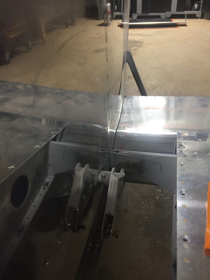
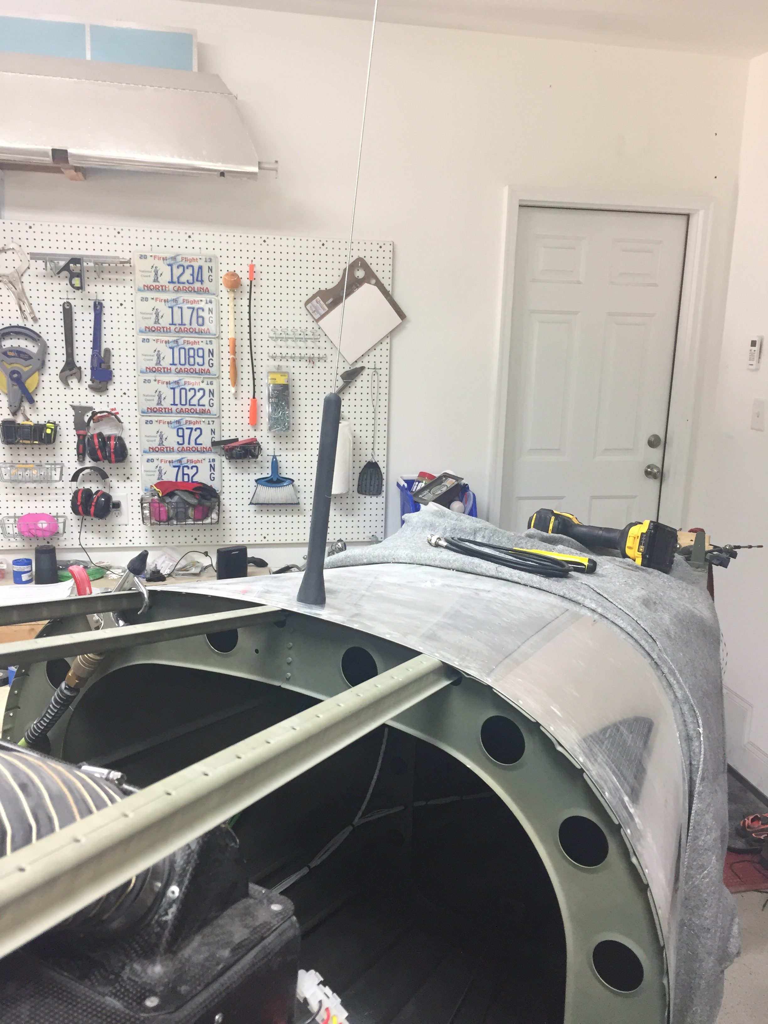
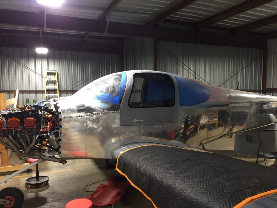
We got the wings back on and permanently bolted on.  I had to order a few washers as the nuts bottomed out on the threaded portion before they should have.  I just added one washer on each bolt and got the proper torque value with no spinning in the hole.  I did the same with the main landing gear bolts on advice from another builder who had a bugger of a time replacing the bolts after the holes elongated.

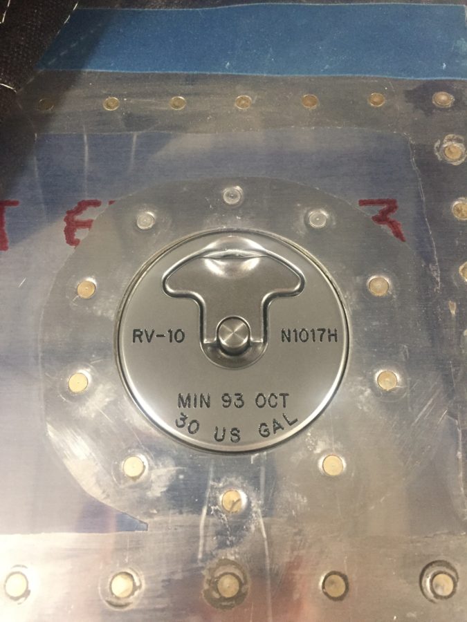
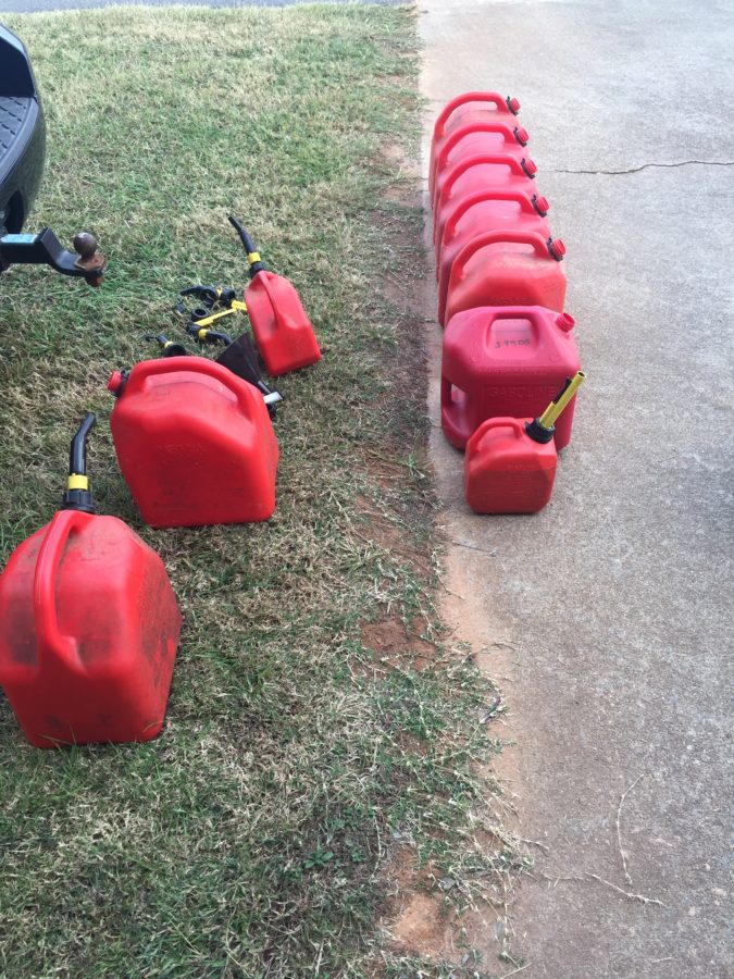
Fuel testing is next on the list and a big hurdle to climb over.  We had pressure tested the tanks, but I was still a bit nervous to put avgas in them for the first time.  I collected all the gas cans I could muster and had enough to hold 36 gallons for the first fuel tank test.  I also bough two two-gallon cans to calibrate the fuel senders.  This test is not only for the tanks, it will see if I have leaks in the lines and will finally show what fuel flow the pumps provide, a key test point for first engine start and flight.

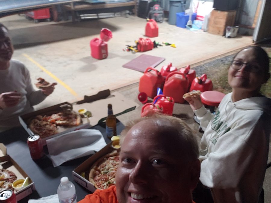
We started by filling the left tank at two gallon intervals and capturing the value on the avionics to create the level points.  The cans nor the amount in them were exactly precise, but it was close enough.  Parish and Jacquie came over and helped us with the reward of eating pizza on the ramp after filling the tanks.

We did 30 gallons in the left and then removed the sump drain to empty the tank and prepare for calibrating the right tank.  The right went pretty easy and we had no leaks on either tank!  I was nervous about leaks but the tanks held great.  Parish and I worked out a good technique of draining the fuel and switching gas cans.  Much easier with two people!

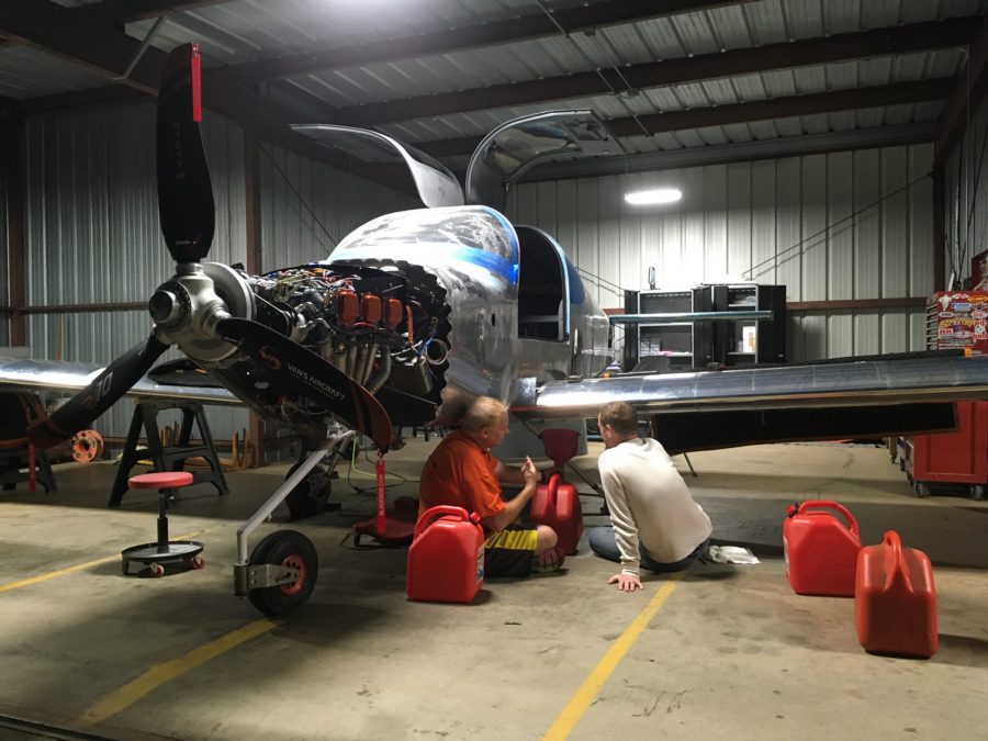
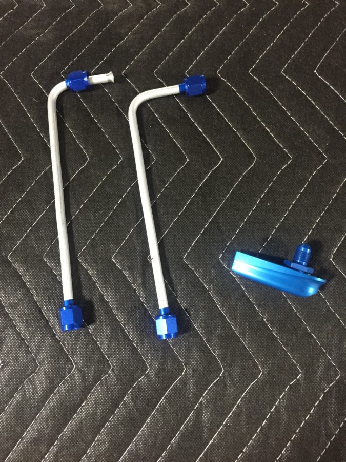
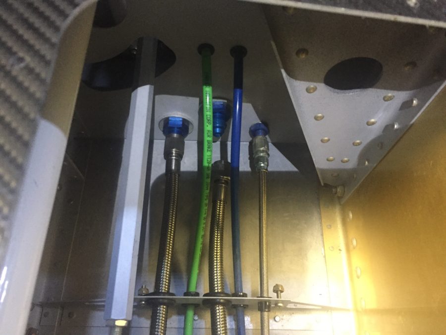
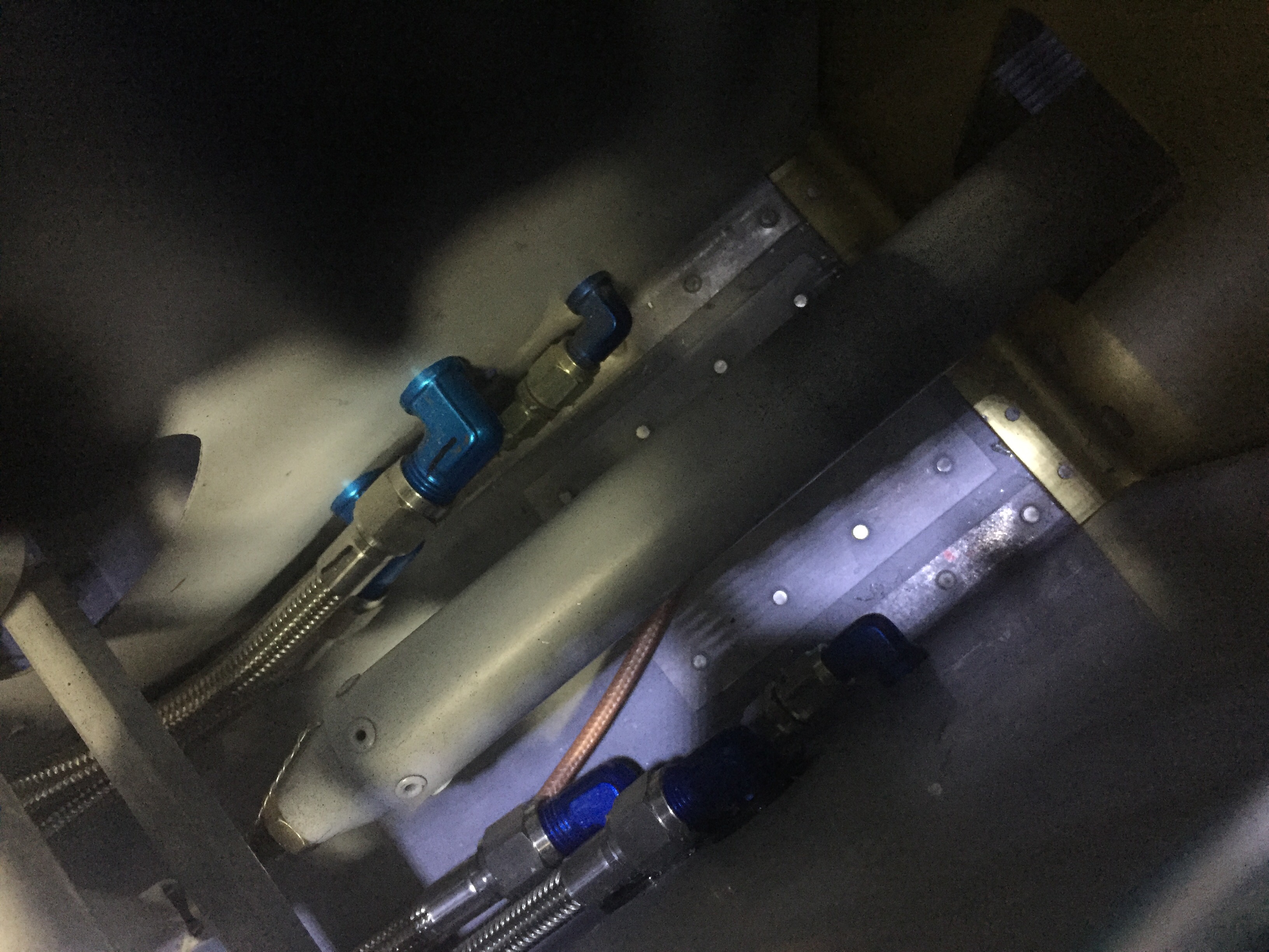
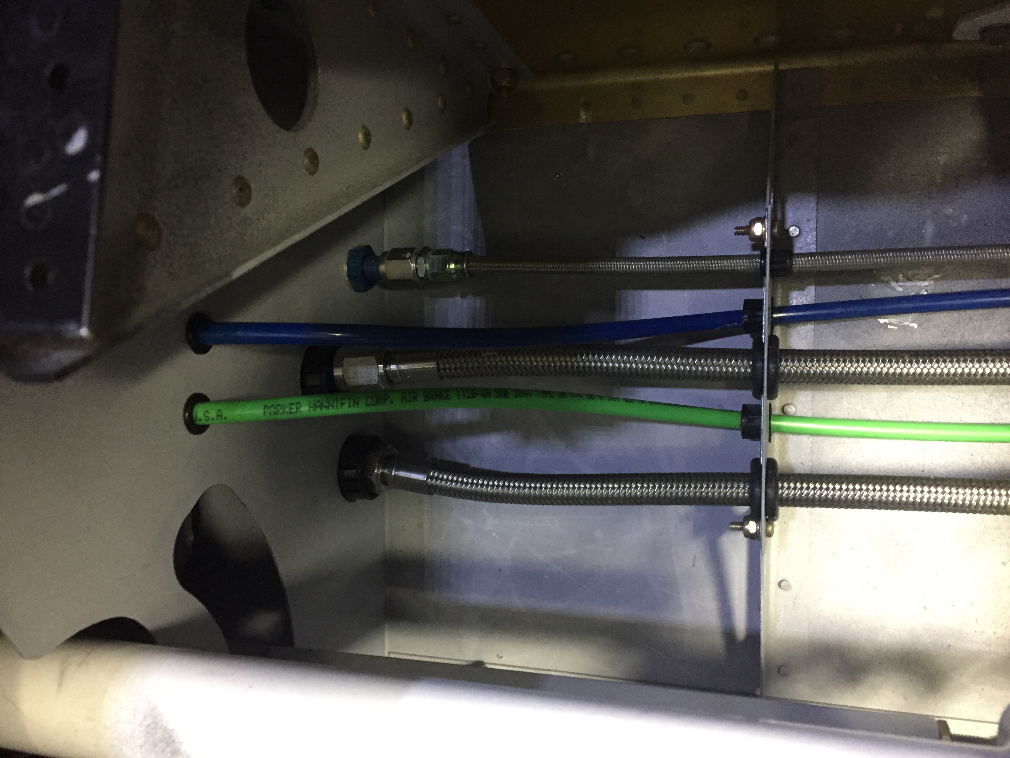
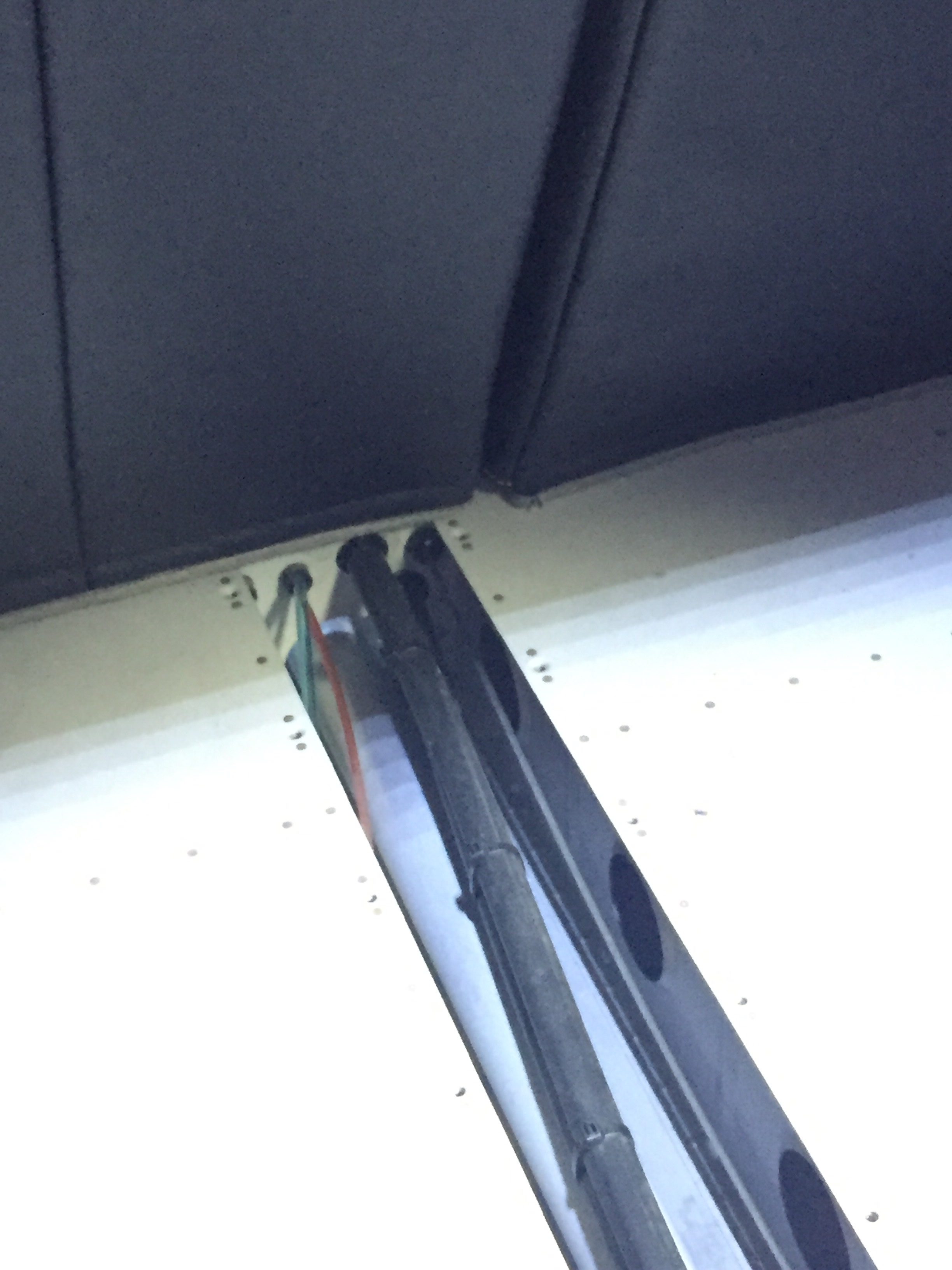
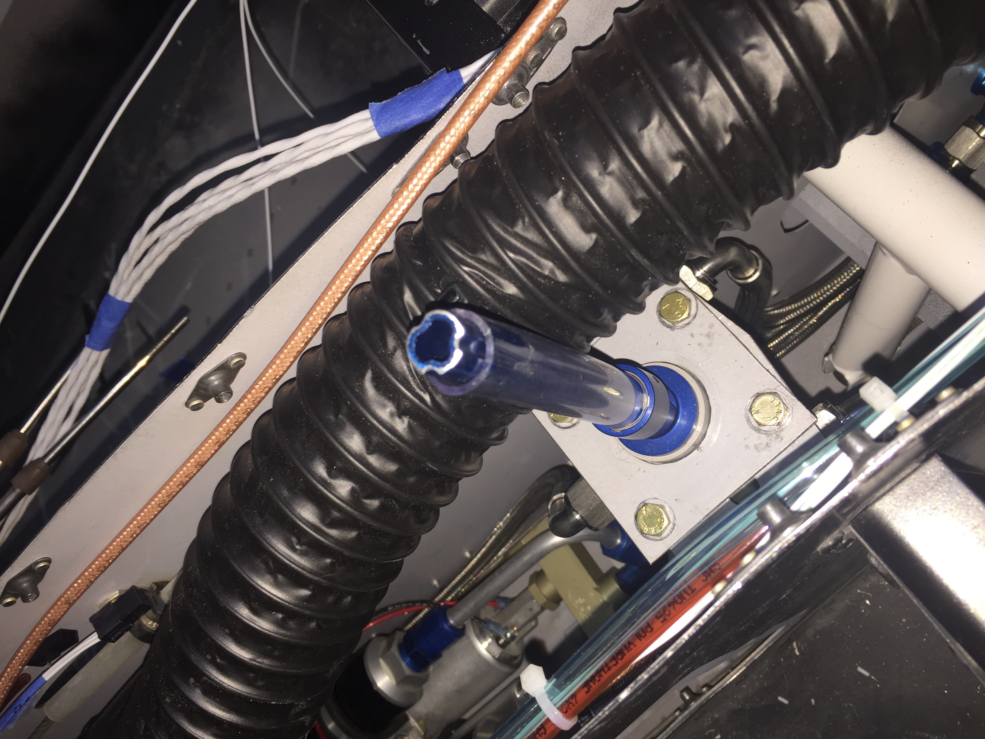
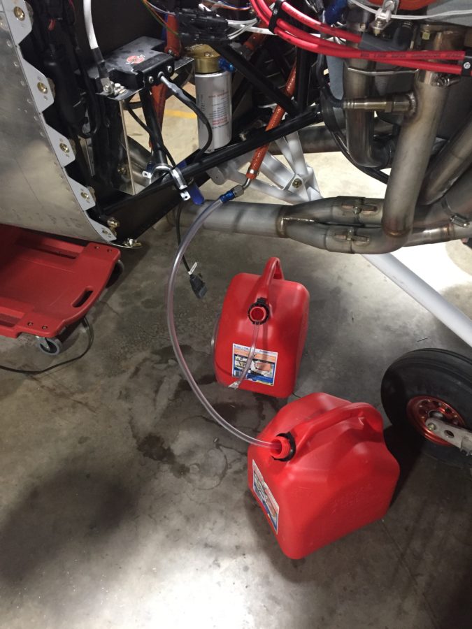
After the right tank was calibrated, I removed the return line from the firewall and put in an empty can to get ready for the flow and pressure test.  It took a few long seconds for the pump to purge air and draw fuel, but after what seemed like eternity, the noise changed and the pump got a hold of liquid.  Unfortunately, that liquid came spewing out of the firewall instead of the hose!  Turns out I mixed the fuel supply line and return line on the tunnel side of the firewall.  That caused a big oh shit moment!

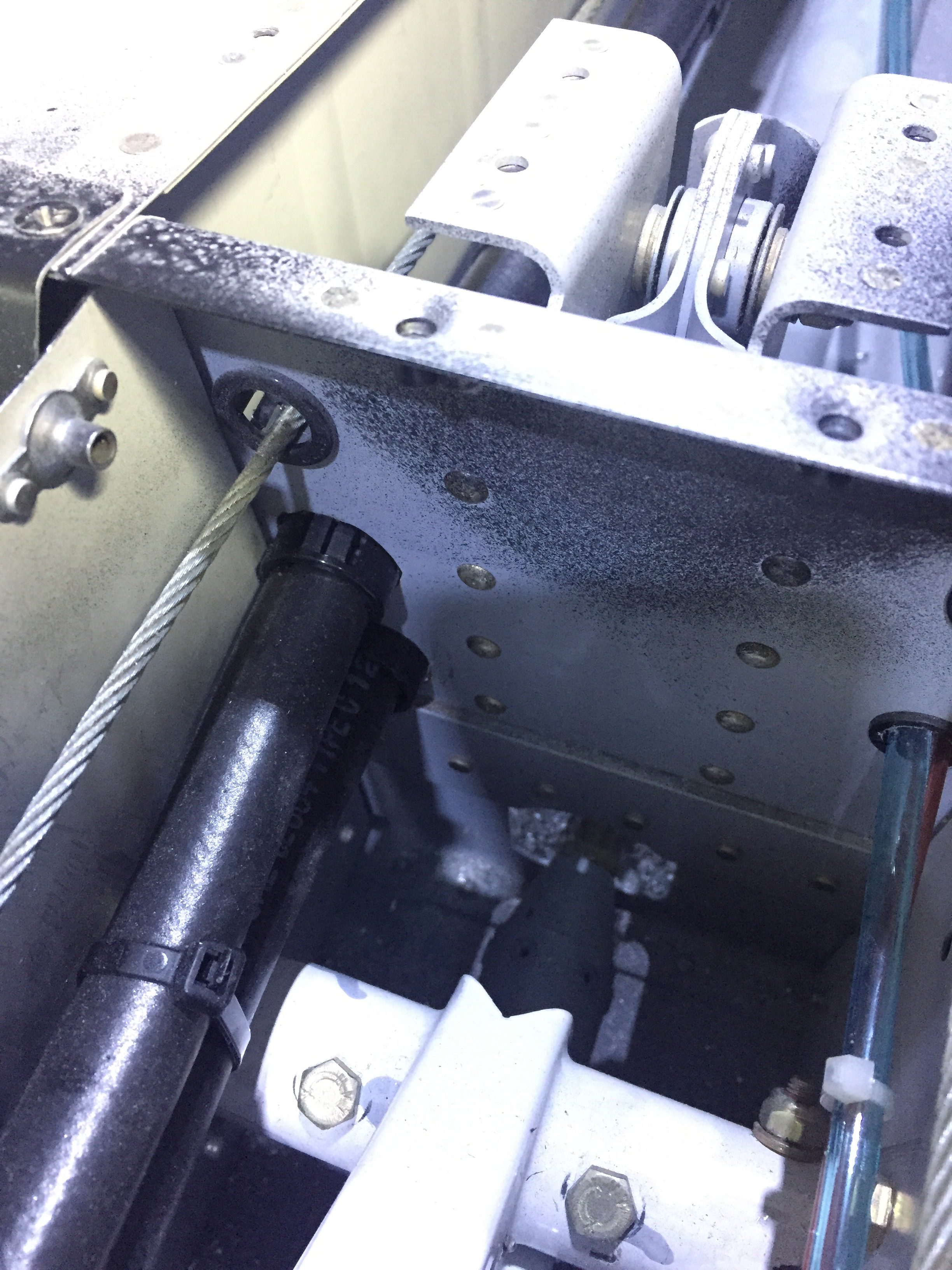
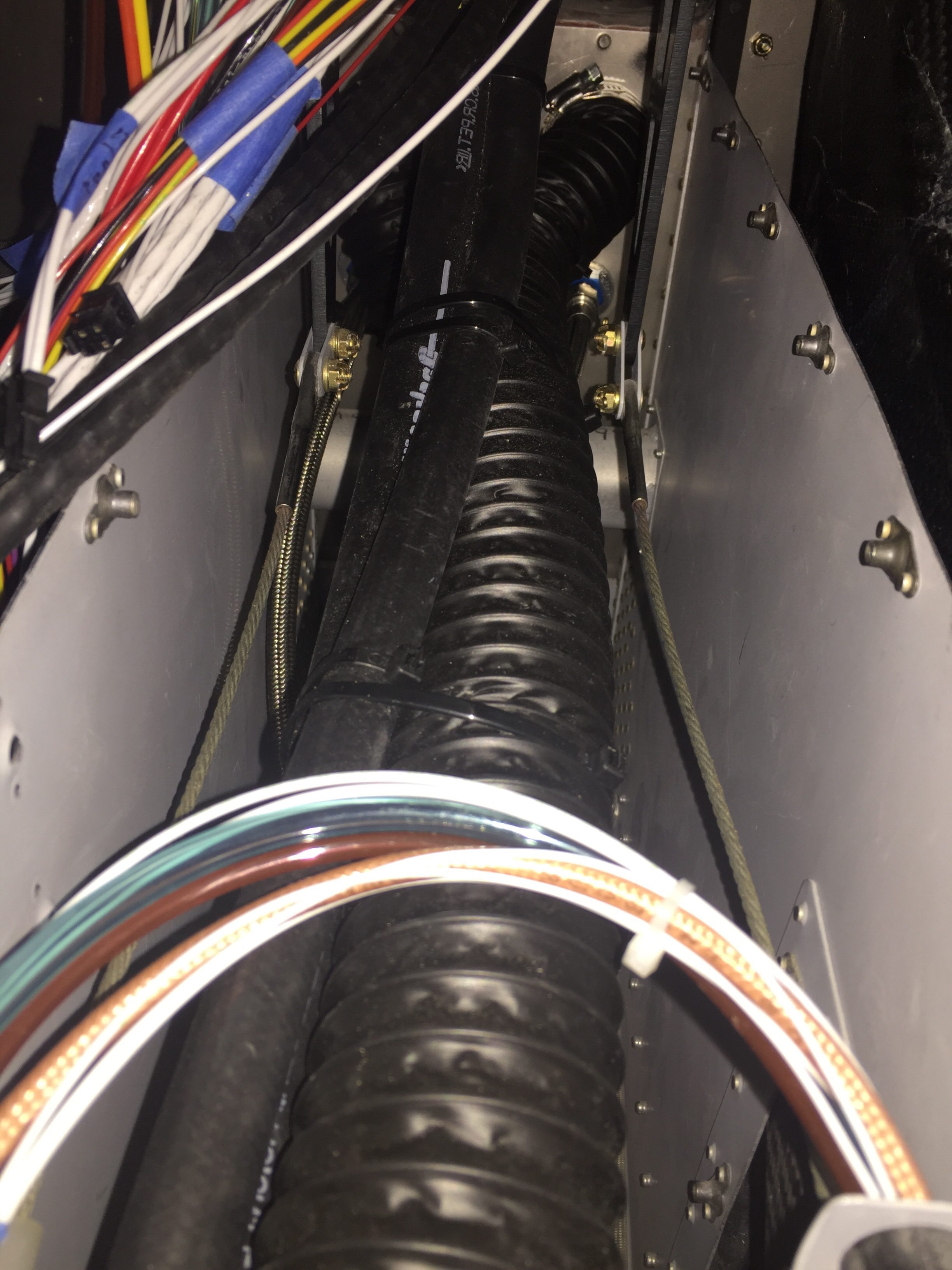
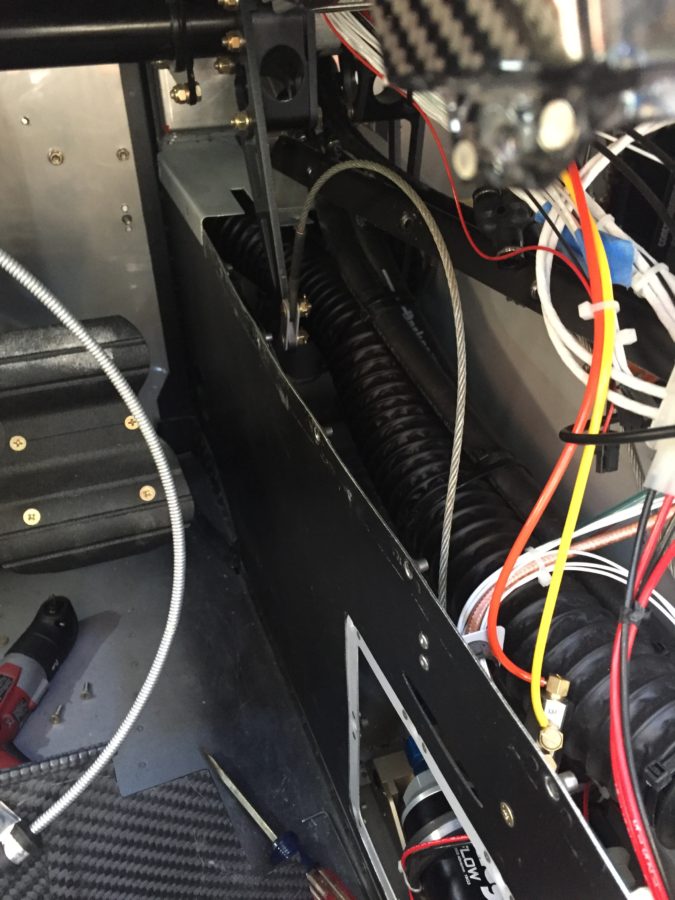
A bit of head scratching and cussing lead to digging in the already disassembled tunnel even more to get at the firewall.  Folks, not an easy task.  Two extensions, crowsfoot, and a lot of scratches, but I was able to get the lines un-crossed and hooked up on the tunnel side correctly.  

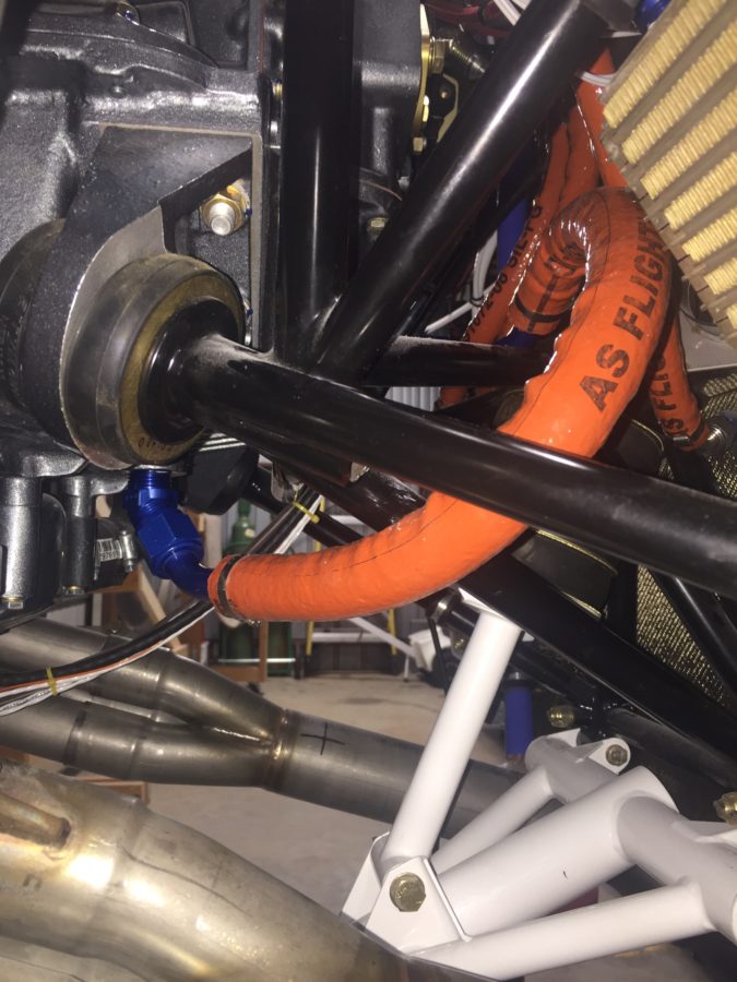
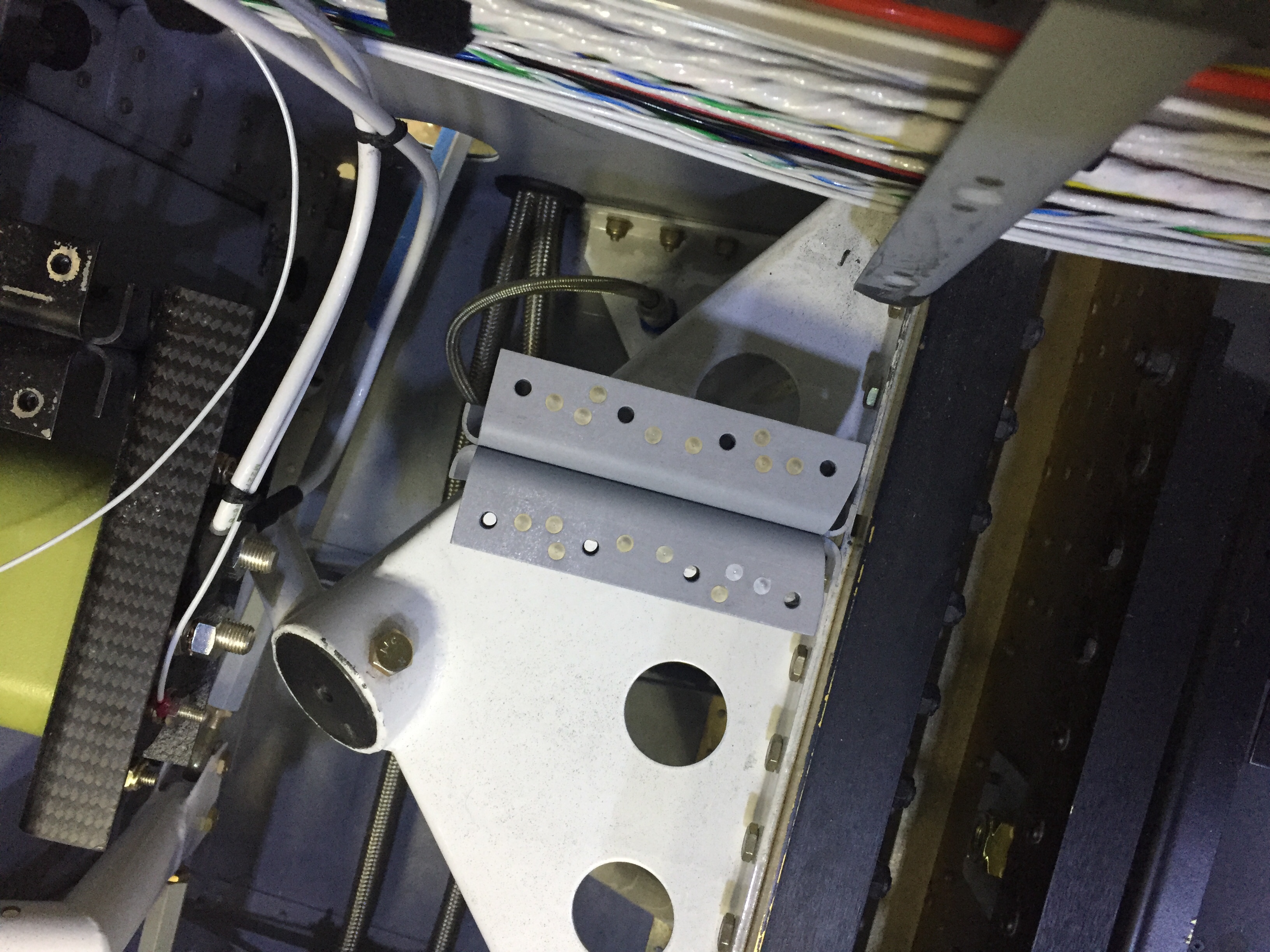
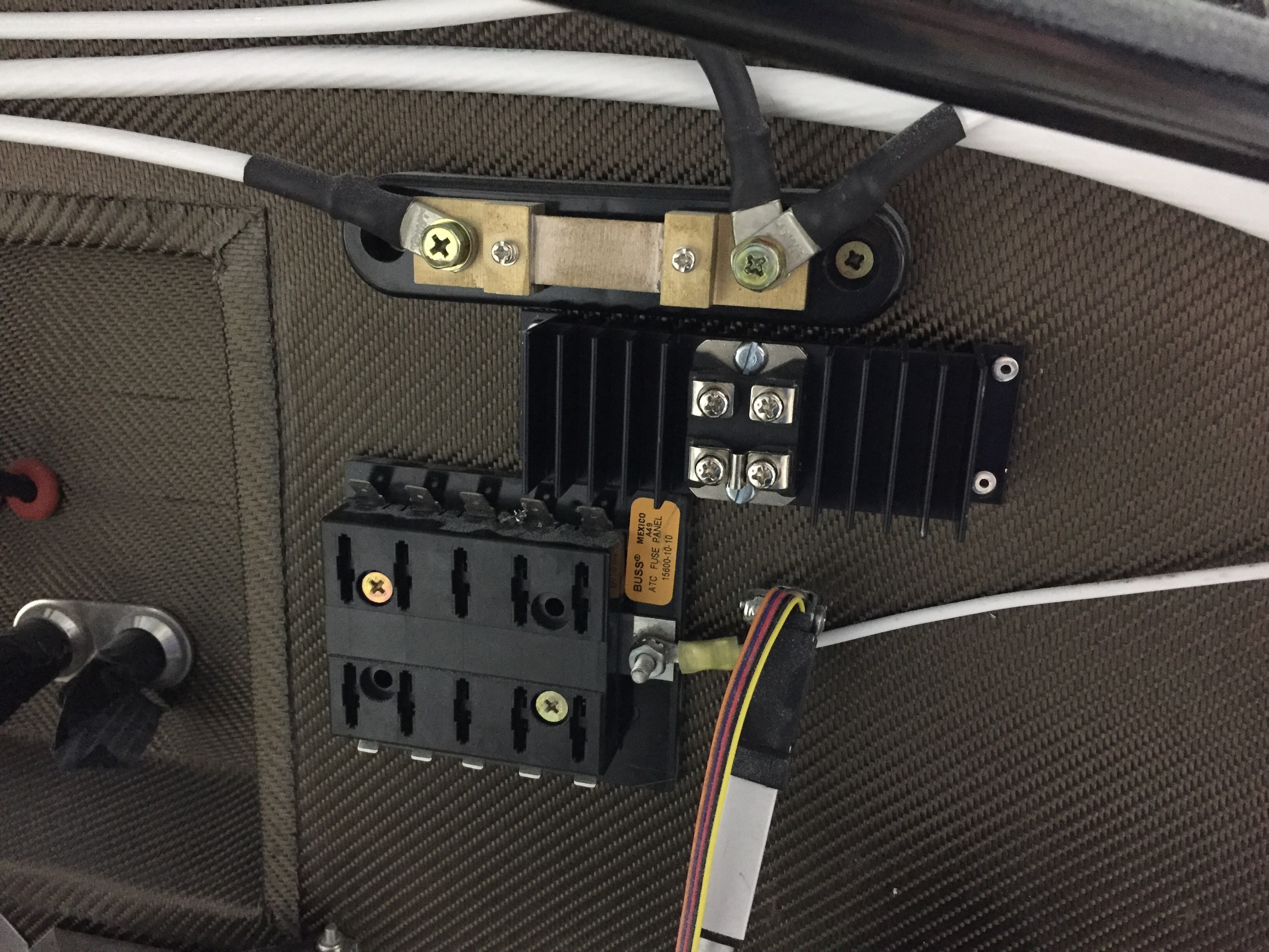
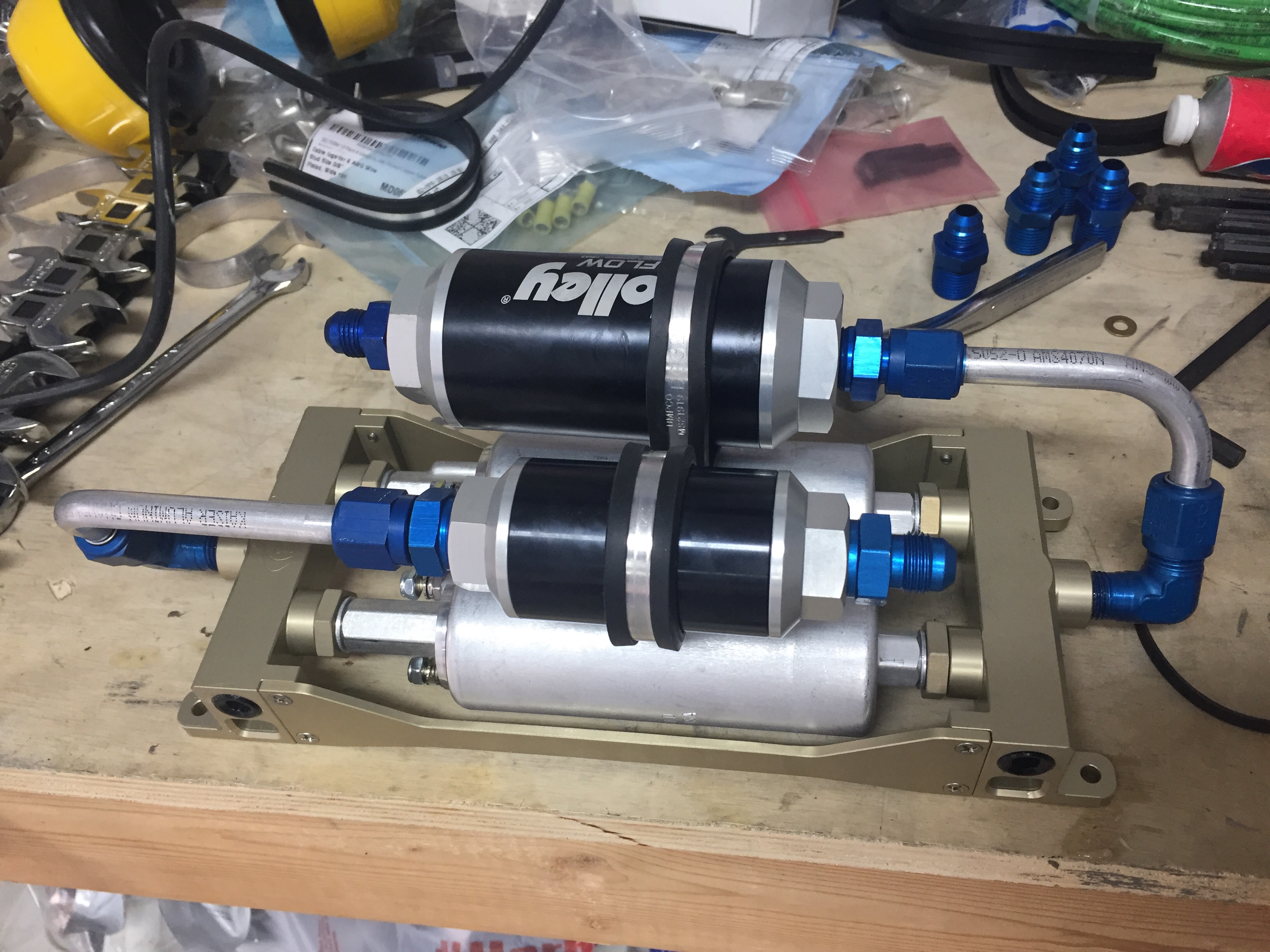
We flipped the fuel pump on again and had fuel coming out of the correct line.  We also had fuel coming out of the filter fittings.  Yup.  So, back in the tunnel I go.  Like an idiot, I didn’t use fuel lube (EZ Turn) on the AN NPT fittings into the fuel pumps.  I did for the fuel pumps manifold, but not the filters.  Gah, idiot.  So I had to take the whole fuel pump/filter module out and get at it on the bench.  While it’s not impossible, it’s not easy.  I’m definitely putting another tunnel access panel on the copilot’s side during the first annual.

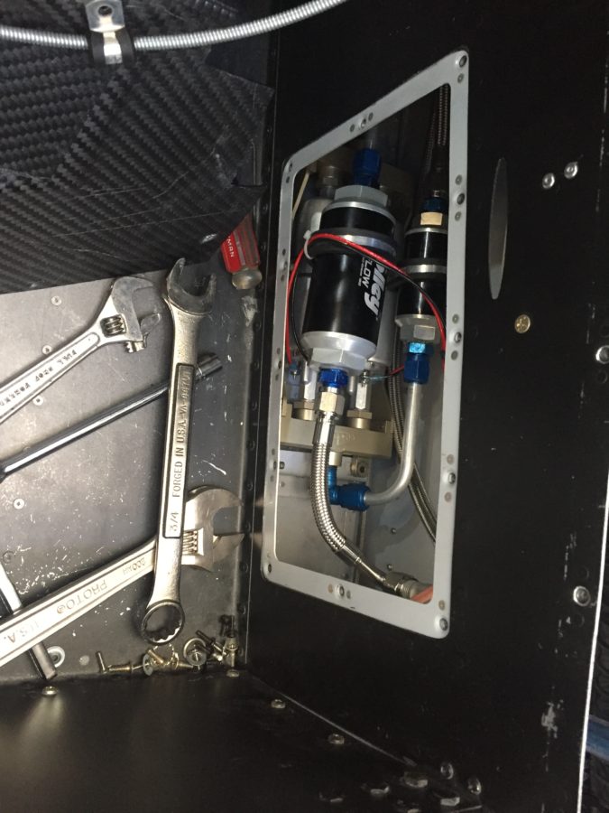
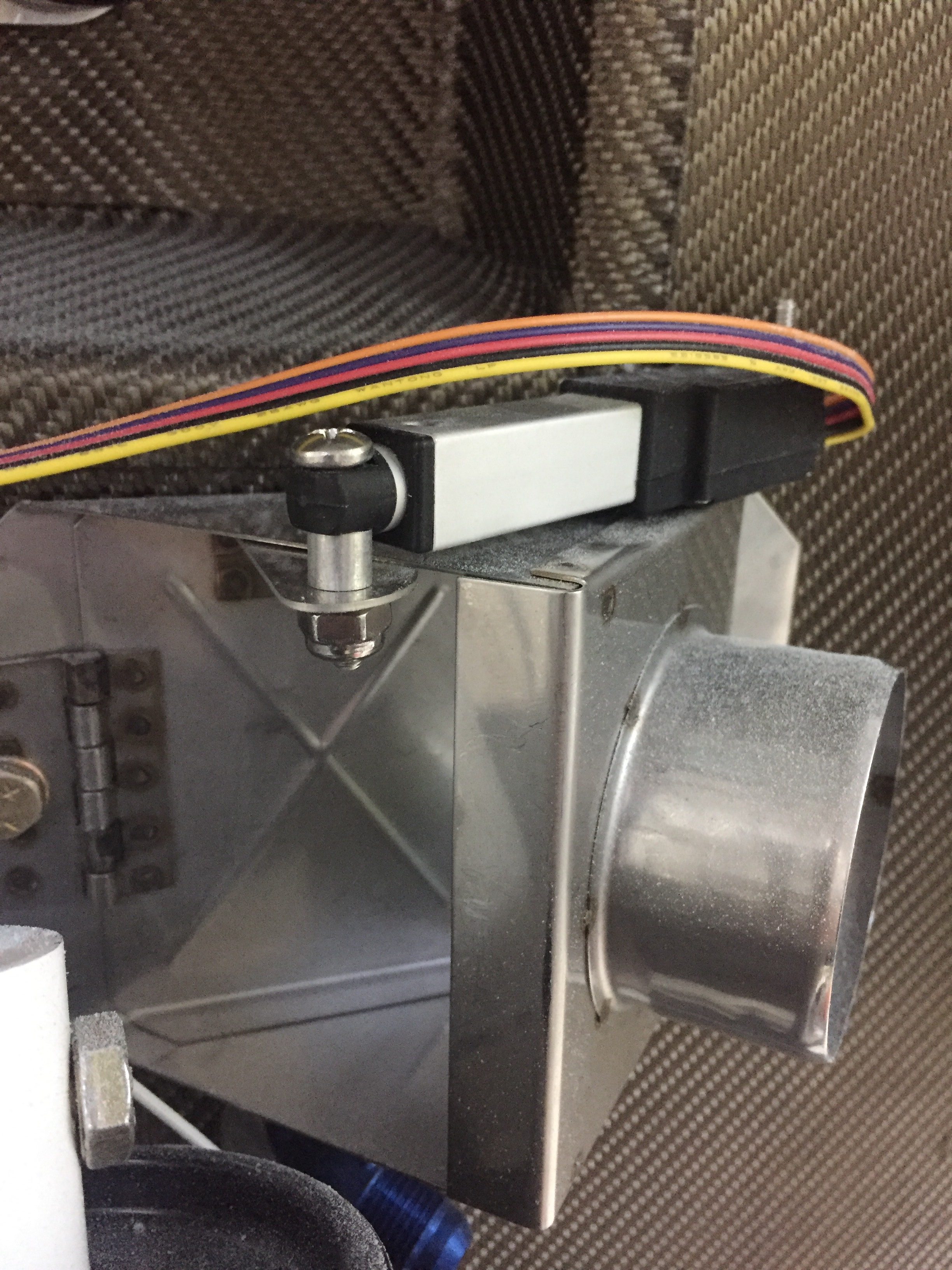
Fittings were properly lubed and torqued, so the module went back in and we turned the pump on for a third try.  That was the ticket, as we got good pressure readings and good flow.  I turned the pressure up a bit to 45 PSI on the regulator and we did flow tests equaling 45 GPH on a single pump and 75 GPH with both on.  Plenty of fuel to feed the thirsty engine on take off!

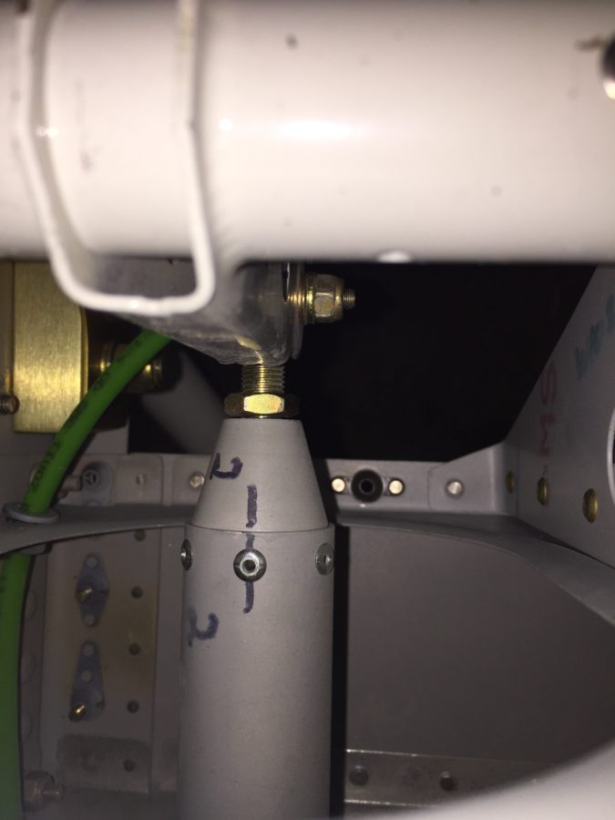
Tess had one more surprise for me, though, when I attached the return line back to the firewall and found one more leak, this time at the outlet of the pressure regulator.  Seems that I didn’t torque that line at all.  Oops.  Again, this is why you extensively ground test!  Got that one all fixed and ran the pumps for about 30 minutes, just recirculating fuel with no issues.  She’s ready for engine start!

Back to my roots

The wings are initially fitted to get the wing root covers installed and hook up fuel lines, vent lines, while getting the flight controls initially rigged.  The wing root cover brackets went on quickly and I fabricated the two fuel vent lines that exit the bottom of the wing root cover.

You also drill the bolt hole in the rear spar and work out a few other fasteners.  I installed the flight controls and worked out the stick to the plans while adjusting the rigging and pushrods.  It wasn’t too bad of a process with a little patience and double thinking before adjusting a rod end the wrong way!  In an afternoon, I had all the controls lined up nicely with the wingtips and fuselage just as described in the plans.

I also finished up the fluid lines up front.  TS Flightlines really came through again on an awesome product.  I had one line that didn’t quite fit to standards and the return lines for the fuel tanks from the tunnel had the wrong fitting (my fault) on them, so those went back for modification.  If you don’t know, TS will rebuild the lines for free until they are correct.  You get what you pay for and I’m glad I spent the money knowing I’ll have lifetime quality hoses.

On a side note, my engraved parts came back looking fan freaking tastic.  The door handles are an extra set that I had and will go on after paint.  The data plate turned out perfect, as did the fuel caps..

Speaking of fuel, a while back I misdrilled the holes in the tunnel on the right side for the fuel line.  I decided at that time to just use a 90* elbow but that made torquing and replacing the incorrect fuel line difficult to say the least.  So I broke down and ordered 90* bulkhead fittings to do it correctly.  I had to dig into the tunnel to put the proper spacers (covering up the now too large hole) and secure the lines from the fitting to the fuel valve.  Boy am I glad I did this, because while looking around since I was in there, I discovered a cross threaded line on the fuel valve that would have made a mess come testing time.  I was able to clean the threads on the fitting and got it on correctly.  I took my time to reinspect all other fittings and lines.

With the airworthiness inspection scheduled for early November, I am shifting into inspection mode so try to check everything I can while working in an area.  It just so happens that the 137 articles Vic Syracuse has written for KitPlanes all mention loose jam nuts!  I want to break that chain but came close to being a statistic in your next bathroom reading material.  The left aileron jam nut had just enough space that it caught my eye while working the fuel lines.  Ha!  Not today, Vic, not today!

Another little side job that had been lingering was wrapping the aircon line with insulated tape to ensure the thermostat coil was in good contact with the line.  I had ordered this sticky tape months ago and finally crawled into the baggage area to finish that up.

Finally, Laura came over to help me pull the wings off so we could prep and install the wing root brackets and finish up the few tasks before permanent install.  This coming weekend will be critical for staying on track towards inspection, as I need to get the entire tail surface wrapped up and the fairings done.  Fingers crossed!

Punching the punch list

There are a lot of little jobs that go along with the big jobs on building a plane.  I’m trying to use my time efficiently while waiting on the engine to knock out a bunch of them.  The first was fixing the arms and servos on the heat ducts up front.  An order to ACS and a few minutes at the band saw and the servos for the heat and oil coolers were attached properly and pots adjusted for full travel.  I also spent an hour trouble shooting a bad pot for the rear heat duct, as I have a switch that allows either the front or rear rheostats to control the servo and the rear rheostat was inop.

I cussed and bled in equal amounts installing the last of the seat rail brackets now the gears are on.  The nuts and bolts are not easy to access at this point, but you have to wait in order to install the gear bolt.  I also put in the last bolt and custom spacer for the GPU plug which helps reinforce the receptacle by attaching it to the seat pan.

I ignorantly forgot to install the transponder antenna before buttoning up the tunnel, so I had to take the center console, tunnel cover, and lower instrument panel off to get down in there.  Of course I burried it near the core of the earth which made access tricky to say the least.  I was able to squeez my hands down there and got it all bolted on with the coax attached.  I knew I had left one fuel line untorqued but couldn’t remember which one so checked all fuel line fittings for proper torque.

The last task in the rear tunnel is to secure the aircon lines which I did with some hose clamps and edge grommet material.  Again, not fun to get to the hardware but it was doable and will rarely if ever be removed.  The lines are now secure and fit nicely in the tunnel, I’m glad I didn’t run them down the side of the fuse.  I also secured the last little sections of the O2 lines in the tunnel.

My ELT antenna placement has been a topic of disagreement on VAF, as I really wanted to avoid mounting it on top of the tail cone.  It’s big, ugly, and ugly.  Mainly, though, it’s ugly.  It’s also essential to my life and the lives of my passengers should the worst happen and we have an accident, so I guess it’s important to do it right.  I debated on doing some reception tests with it mounted internal to the tail cone, but honestly, I just got lazy and decided it really isn’t that ugly.  In the end, I chose to do it the right way and put it on the top of the tail cone.  The cable was secured along a bulkhead and the last of the wiring clean up for the O2 tank / ELT was completed.

I love spending time wiggling back into the tail coffin, I mean cone, so I made a fort with blankets and towels and dove in to attach the OAT sensors to the ADAHRS and finish securing tail cone wiring.  I put the OAT sensors below the access panels underneath the horizontal stab since I had all of my wing wiring complete and for shorter wire runs to the ADAHRS.  Since they have to be calibrated anyway, I’m not too concerned with exhaust from the engine affecting them too much.

The O2 tank was put back in for good and connected to all of the lines.  I also attached the pitch auto pilot servo to the bellcrank and will connect the yaw servo once the tail feathers and rudder cables are rigged at the hangar.  That is the last task in the tail cone and can be completed without having to crawl all the way back there.  It’s going to be motivation in life to keep from getting fat or have a small child that can slide back there for maintenance, it’s a very tight fit with all the extra stuff I put back there.

More zip tie work on the side walls as I cleaned up all of the wire bundles.  I was lazy and didn’t lace them.  If you don’t like that, you go build your own damn airplane!  Lots of zip ties.  Overall I’m happy with the wire runs, I was able to keep coax with mainly data / signal wires and have the high current ones seperated.  I have seen plenty of aircraft with everything bundled together without issues, so I think it’s more important to terminate and ground properly than anything.

The pitot / AoA tubing needs to run across the fuselage from the left wing to the right sidewall, so I put two holes in the tunnel and used free holes from the fuel line anchors to run the blue and green tubing.  The wing is already plumbed, so these lines will connect with those from the wing with two connectors and be done.

Finally, I put the 30 amp Schottky diode on the firewall between the shunt and engine fuse block.  I had this in my electrical design but just in the wrong location.  It provides redundant power input to the engine fuse block only, keeping it from backfeeding the rest of the electrical system.  The power comes in from the emergency engine power switch which comes from the battery to the fuse block.  Big picture, it is a redundancy for the single point of failure of the master contactor or short in the system.  A complete electrical failure or engine stopping SOP will be to turn off the master switch (leaving PFD, MFD, and G5 operating on independent back up batteries) and switch on the emergency engine power switch.  If the battery has any juice at all, it will go only to the engine fuse block.

Tunneling toward the fire(wall)

The tunnel has been somewhat neglected for quite a while, so it is time to tackle it and put the cover on.  The first main task was to finish the fuel lines and install the fuel filter and pump assembly.  I got Ross from SDS to send me the dual pump assembly as well as the filters so I could go ahead and install them prior to getting the engine.  Tom at TS Flightlines has a great setup that puts the filters on top of the pumps with adel clamps using hard lines.  Flex lines are used in the rest of the fuel line system.  Tom was super to work with and we soon had all the details worked out to get the lines ordered.  I set about building brackets to mount the pumps on and it will ease removal and installation (somewhat, it will still be a pain) in the future once it is all covered with the interior.

I also got a plate made for the fuel pump to mount on since the Andair bolt holes don’t line up with the stock bracket quite right.  I turned the face plate such that the left and right wording is on their respective side of the aircraft which should help in muscle memory and recognition during my scan.  An easy fix which lead to a lot of sweating and cursing fitting the lines and torquing them in that tight space.  Unfortunately, two lines didn’t work from Tom on the initial fitting.  He really goes above and beyond, however, and will re-make the lines until everything fits for free.  These aren’t the cheapest option, but they sure are nice and pressure tested as an added benefit.  Something I couldn’t do until putting fuel in the system and creating a big mess with a little leak.

The second main task was to finish the aircon hoses that I chose to route down the tunnel instead of the sidewall to make more room for wire runs.  It also eliminates some bulging on the interior panel up front near the rudder pedals.  I measured out the hole size needed including the grommets that will allow for the hose to pass through with minimal clearance.  Then I cut out some templates to help position them on the bulkheads that needed to be drilled.  This allowed me to play with edge distance and place them where edge distance is maximized as much as possible.  I got a cool new 90 drill adapter tool for this task and used it with my cordless drill to get the holes made.

Up on the firewall, I chose to chain drill the large holes for two aircon hose bulkhead pass-throughs which worked really well and saved a lot of work with a big bit in the stainless steel.  The lines fit very nicely between the rudder cable arms once secured vertically.  The hoses route on the right side of the tunnel over the spar and clear the rudder cable just forward of the flap motor by being secured to the rudder cable guide bracket.  I’ll clean up the rear tunnel area later with a few more secure points and edge grommets to protect the hoses.

I also routed the heating ducts and actually fit everything where it needed to be!  I mashed the rear duct a bit to mold it around the fuel valve stem.  I also put a piece of vinyl tubing around the stem to avoid any interference against the duct.

With the newly made lines from TS Flightlines installed, the tunnel is all ready for the cover and to be buttoned up.  I reached out to Vic Syracuse, who I plan to use as my DAR, to ask what all he needs open for the inspection.  He advised the rear tunnel cover needs to be off but the front can be on so that fuel valve, throttle quadrant, and center console can be installed.  So, the front cover went on after a good cleaning and ideally won’t come off again for a long long time!

Dirty Door Details

I want a really finished looking product for the doors which requires covering / filling in a few key spots such as the pin guides, hinges, and install holes for the gear rack and center cam.  Some have laid fiberglass over these areas, others have left them open, and a few folks are using basswood to create cover plates.  Since I’m better at the wood and had some on the shelf, that’s what I chose to do.  The pin guides I just roughed up and applied flox directly on them, roughing the shape in to match the door lines.  I used some scrap pin material to keep the hole clean.


I used the basswood to fill in a hole used to install the center latch and create covers for the hinges.  It was pretty easy to trim and shape the wood for the plates needed and after I coated all sides with epoxy to harden the wood, I epoxied the plates in place.  I then went back with Superfil and did the final contouring and shaping to match all of the door’s surface.  I’m really happy with how it came out and while it was a bit of extra work, I think it’s worth it in the end to not look at exposed hardware.  I’ll be covering the hinges on the cabin top down the road as well.  Finally, I took some time to fill in little surface blemishes and final shapped the interior edge of the window frame.


After all the sanding was done and I was happy with the doors, I wanted to re-mount them for the final time.  Here is where I realized I screwed up.  The hinges are mounted to the cabin top with the hardware essentially epoxied in (see prior post) so I had to slip the door onto the hinges and install the hardware behind the new cover plate I had spent all that time creating.  Bad idea.  It’s impossible to get the washer and nut on each screw on the door side of the hinge.  My fingers are fat and not triple jointed so I spent an hour raising my blood pressure far beyond healthy limits struggling with it.  I decided to walk away, burn the project to the ground, and start over.  Okay, really, I just took the rest of the night off.  The next evening with a calmer approach, I fabed up a handy little tool to hold the washer and nut in the cavity while I installed the screw.  I used some basswood and some aluminum to create a captive wrench so to speak that worked beautifully.  Had both doors installed in about 20 minutes.  Wish I had put the hinges on the door then bolted them onto the fuselage, but oh well.  I installed the last plates to close out the hinge area and applied filler to smooth is all over.  This completely closes out the hinge cavity on the door not only making it look better but allowing the door seal to work properly.


Meanwhile, I set about working on the instrument panel and center console.  The big Aerosport order had arrived a few weeks prior and I was eager to play with all of the cool stuff.  I started with the instrument panel and got the backing plate and the panel itself fitted in their place.  The side skirts on the tunnel attach to the lower instrument panel with the center console mating up to it.  This stuff is top notch quality and is going to be really awesome filled with fancy avionics!  I took my time to fit it all and used nutplates to ease future maintenance and removal.  I chose to countersink the carbon which left it a little thin and brittle, so I coated each screw hole with light epoxy to help strengthen the area.  I also cut out the main areas which will have the metal inserts leaving a 1” flange to be trimmed to final size later.  The center console was positioned and I used a strap duplicator to drill the holes matching the tunnel.


Since my plans include using the ACM from AFS, I want to use a fancy push to start button but couldn’t really find one that I liked.  The Honda S2000 button others have used are hard to find these days so after a few returned orders, a deep Google search turned up exactly what I was looking for.  It’s a simple Apem NO switch that has a LED light actuator.  It’s also the right size to be proportional to the panel location.  I couldn’t help but to drill the hole and mount it up to see how it looked.


The Andair fuel valve is mounted through the tunnel on the center console as well, so I set about locating the screw holes.  I mocked up the valve itself on the stock mount and will need to create a larger mounting plate for the valve housing down the road.  It allowed me to trim the handle extension and locate the plate on top of the console.  Again, had to mock it up and do some airplane noises while turning the valve.  The noises worked perfectly; so did the valve.


Finally, I cut the throttle quadrant area out and worked on installing the quadrant onto the tunnel cover.  Thanks to Ed and Aerosport’s awesome YouTube video, it was pretty painless and I wound up with a very nice fit with the throttles fitting flush with the console when everything is installed.  I cut a large slit on the throttle friction lock area that allows easy removal of the console.  I’ll create a trim plate to cover up the slit for a finished look.  With the main carbon work done, it was time to drop off the instrument panel parts and center console to a paint shop for a clear coat.  I want to leave the carbon look exposed but wasn’t happy with the finish right out of the mold.  I had originally asked Aerosport to clear the items but they quoted over $1500 just for the clear coat.  I almost choked.  I love them to death and they’ve done a lot to help, but I couldn’t swallow that pill.  A few calls around the area and a local custom motorcycle paint shop could perform the work in four days for $250.  We’ll see how they turn out next.