What’s under the hood?

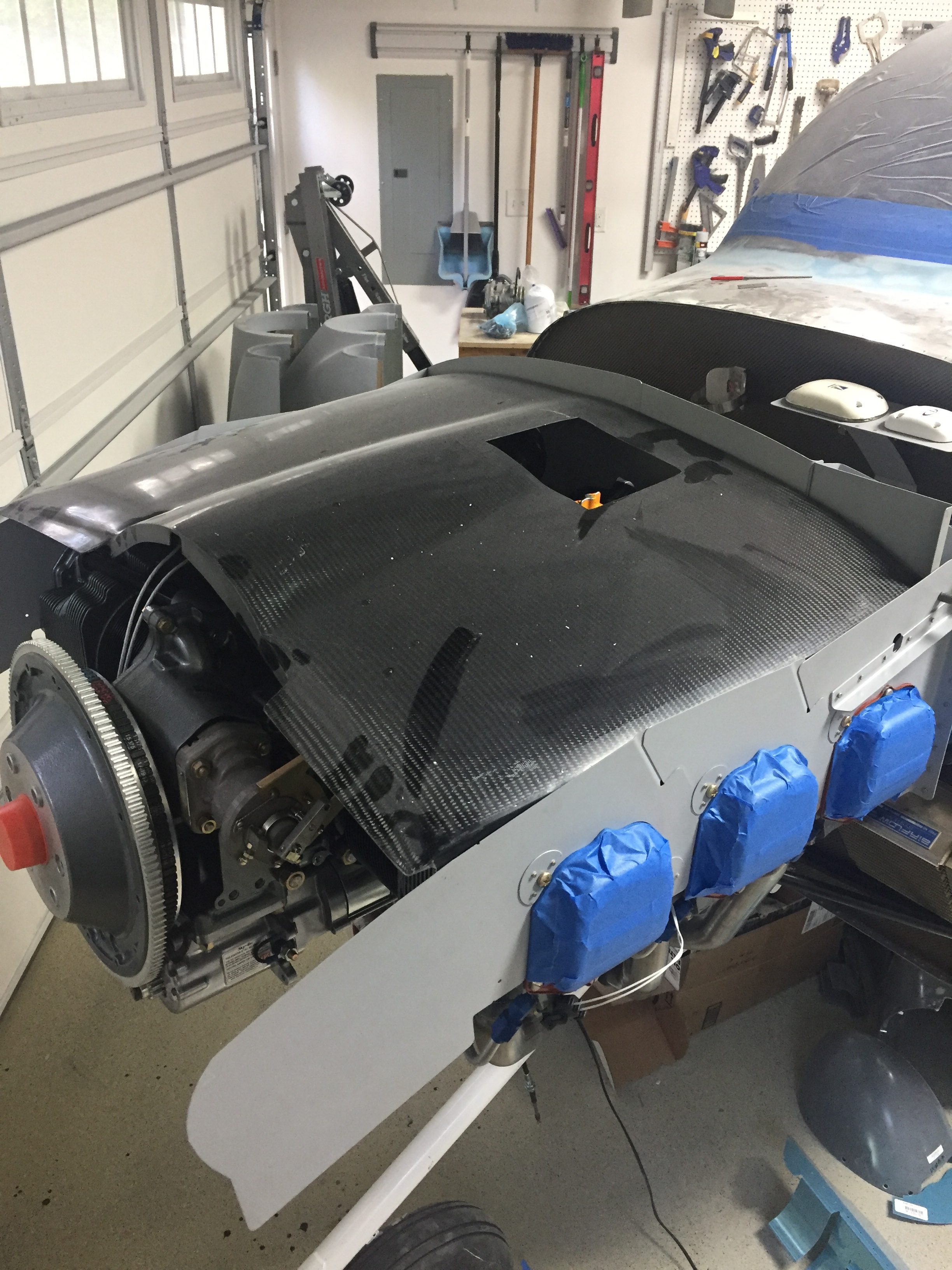
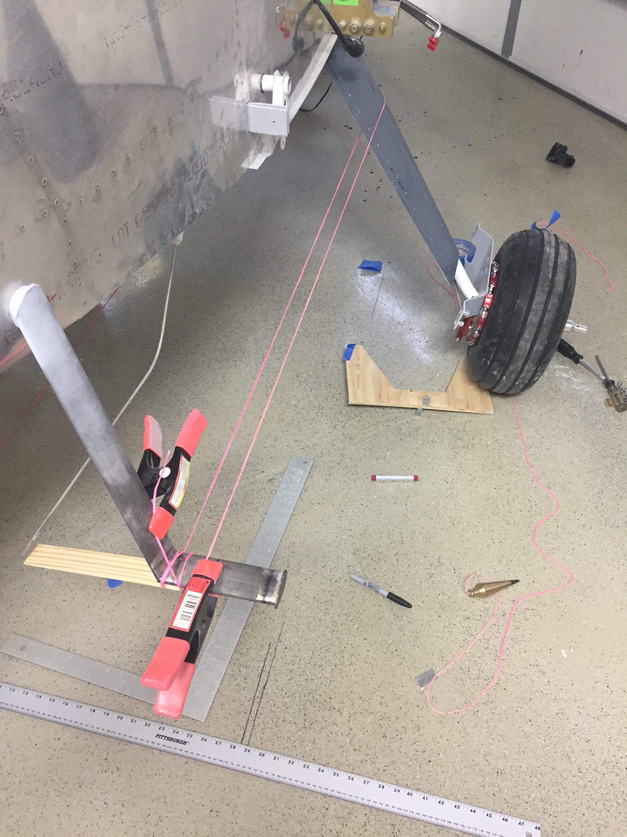
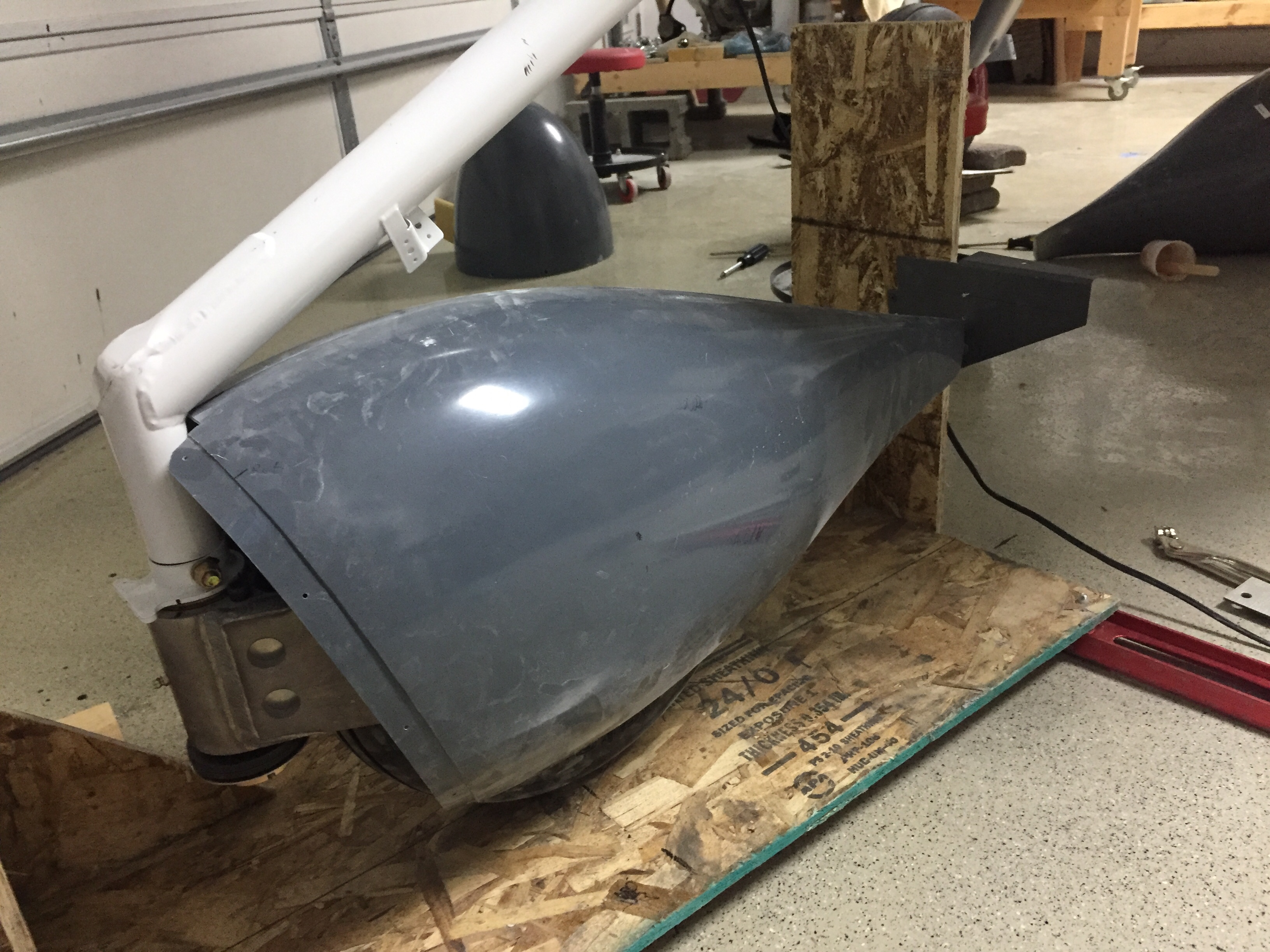
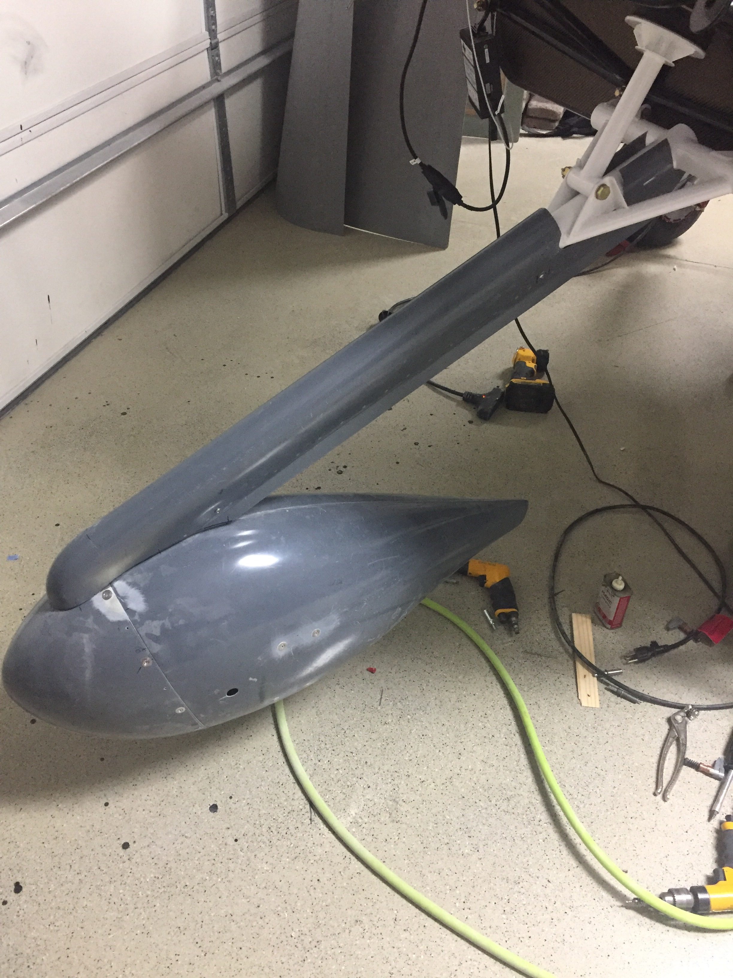
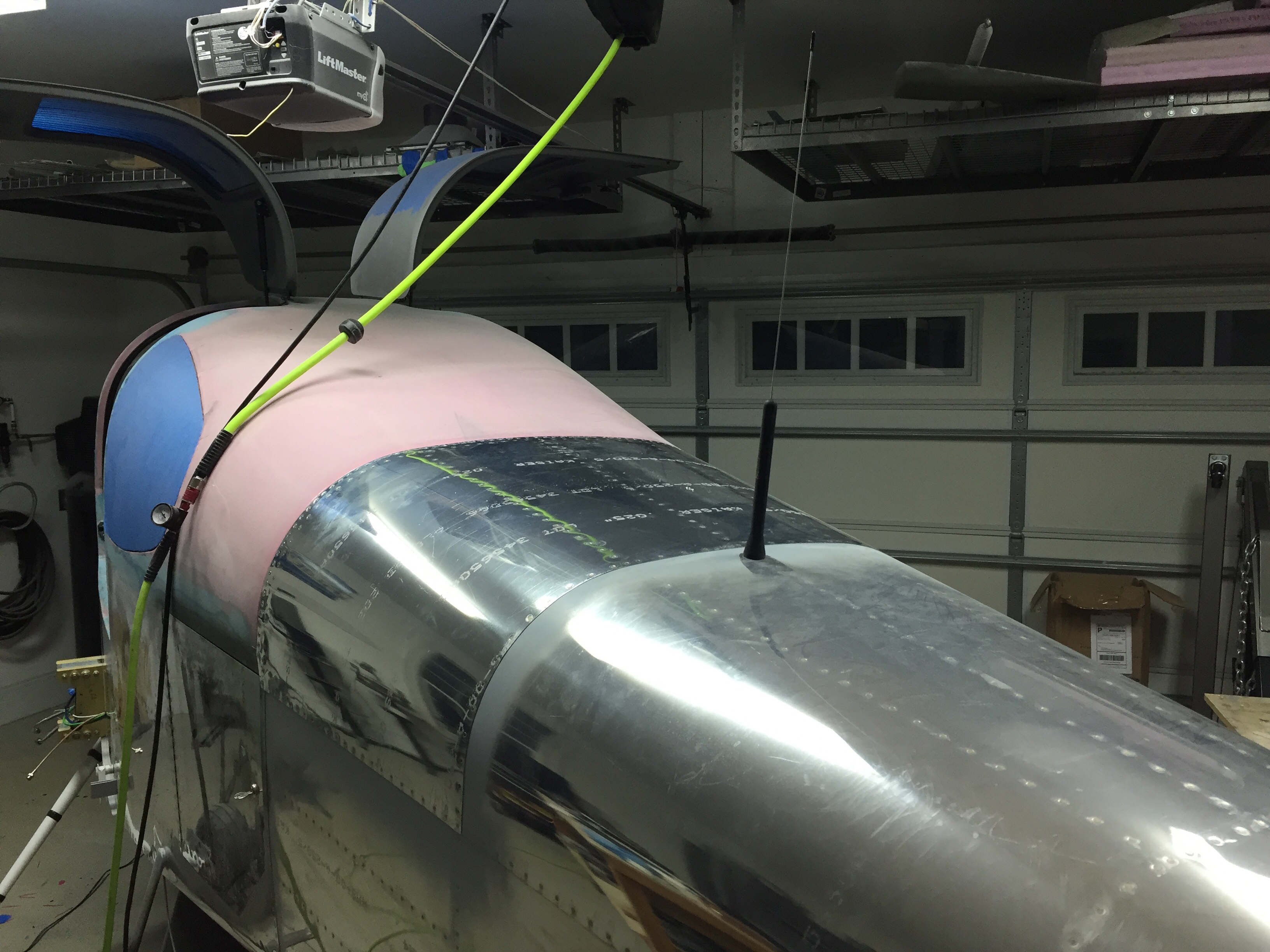
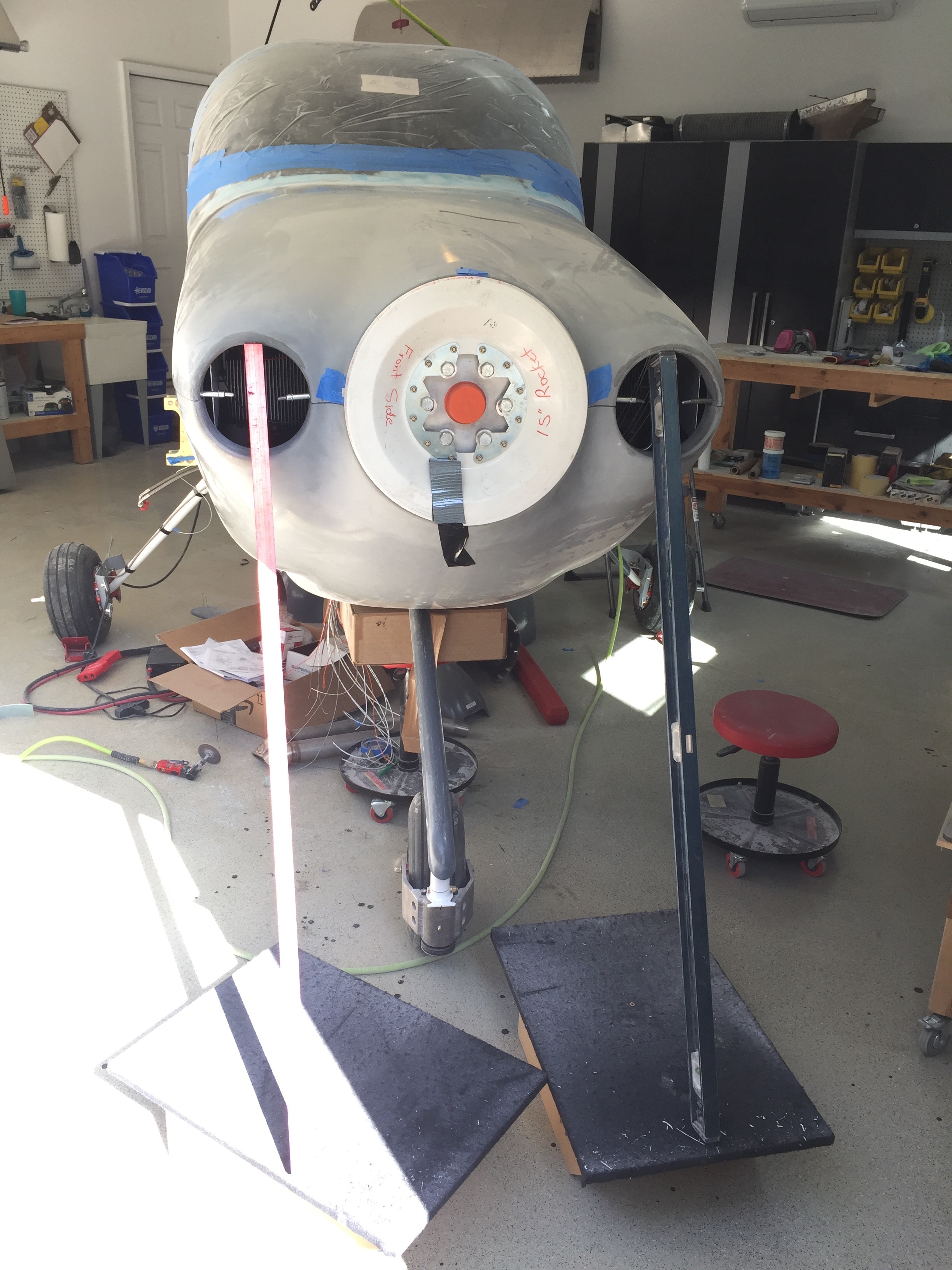
While I worked on the wiring, I made progress with mounting the engine cowling as I’m really starting the countdown to moving to the hangar.  The cowl had been at the airport for months, so I retrieved it to start measuring and trimming.  With the baffles and plenum initially fit, I started with the mock up prop spinner plate from Whirl Wind.  This mock up has spacers that position the backplate as if the propeller was on, which is then used as the template for positioning the cowl.

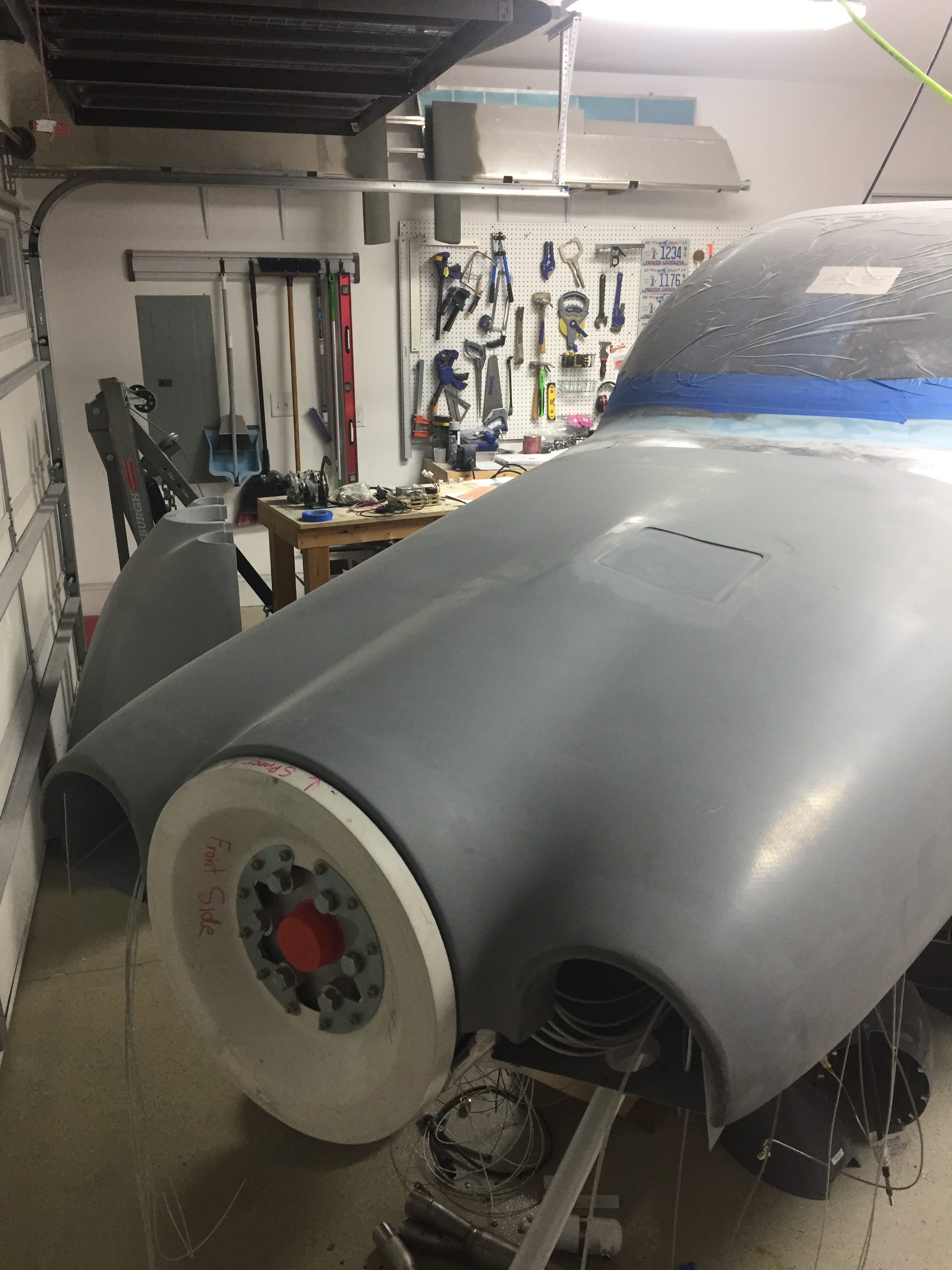
I also used the spinner backplate to tac the cowl halves together and do an initial trim on the front joint.  Clecos worked well holding it in place as I trimmed and ensured a good fit resulting in even circular openings for the intakes and prop.

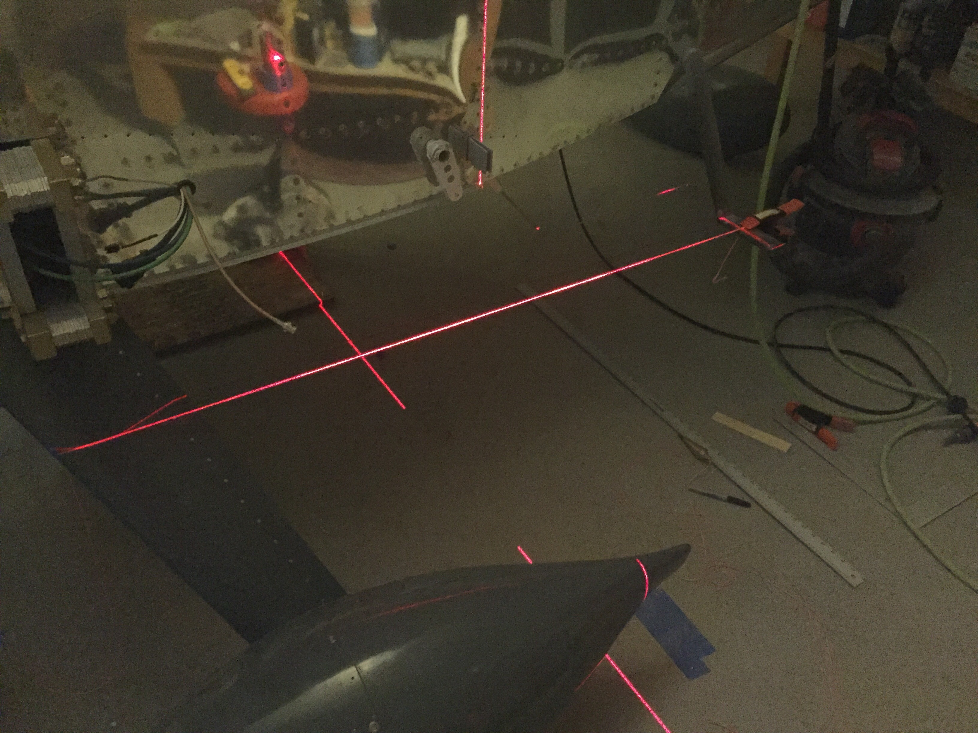
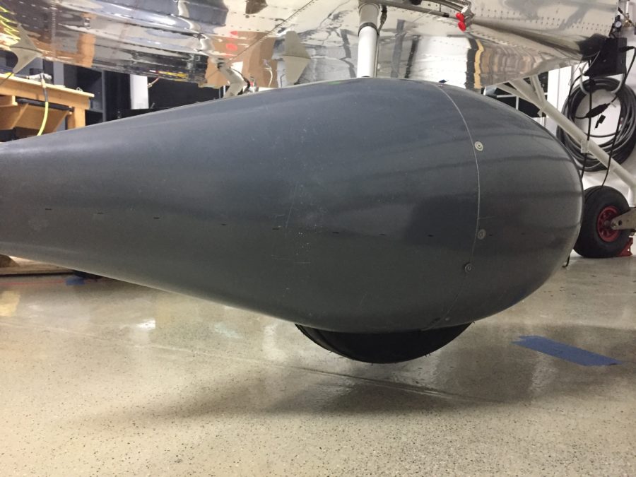
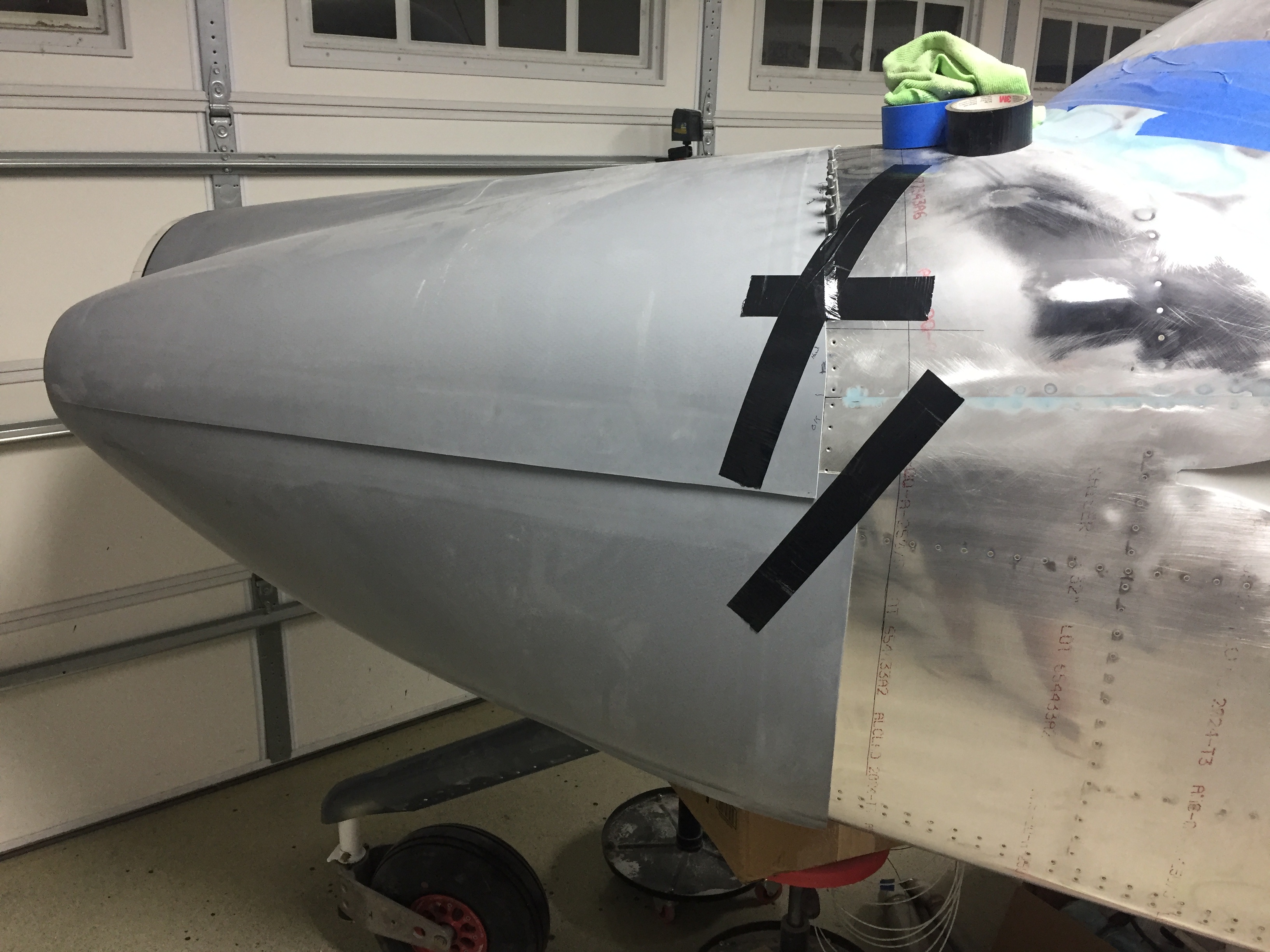
I started with the top cowl, laying it over the fuselage skin and clamping it to the spinner backplate with spacers for a nice clearance gap.  I used the reference line method to mark the edge of the firewall on the cowl overlap and measured twice before cutting it long so I could sand it to fit.

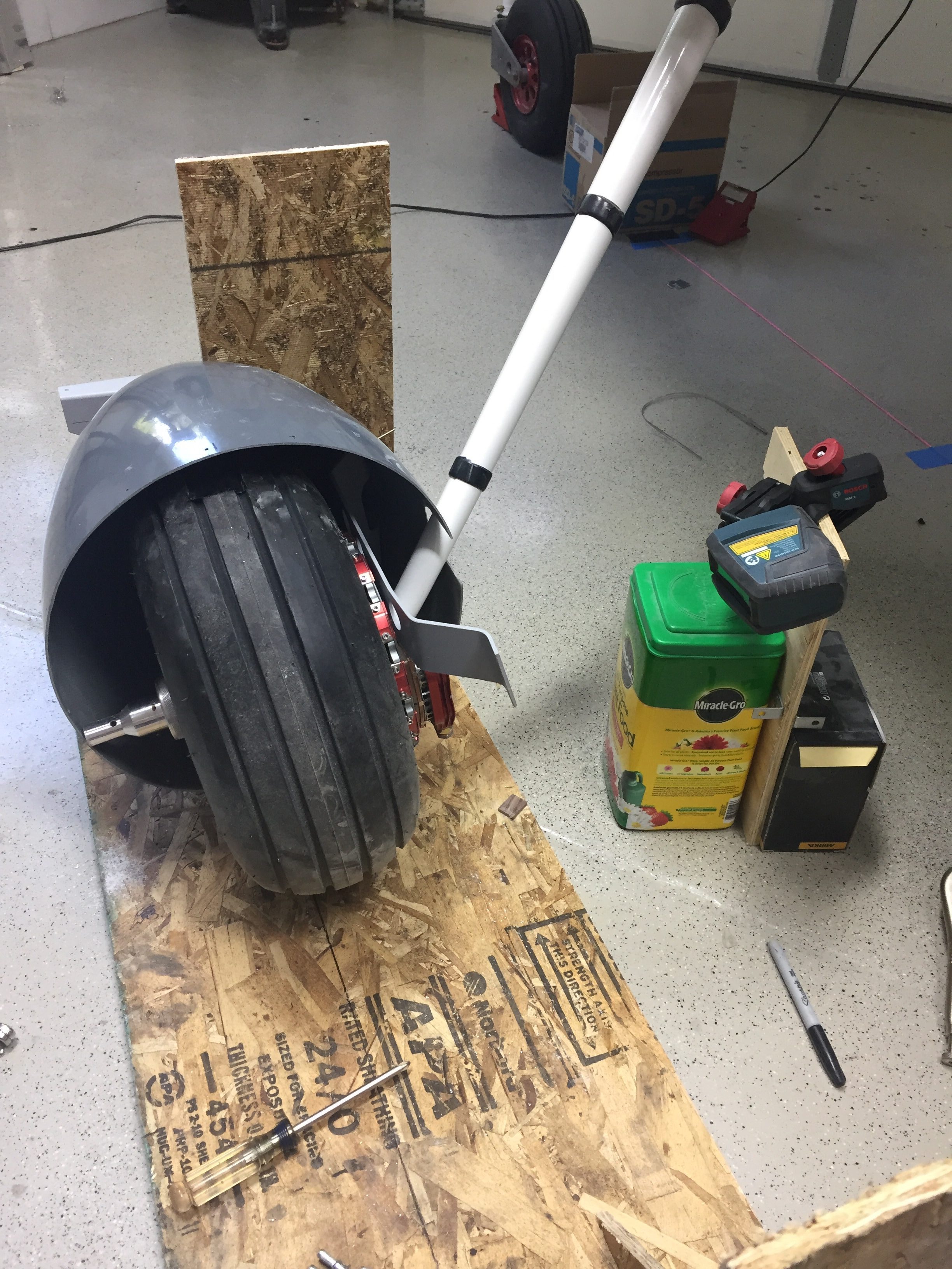
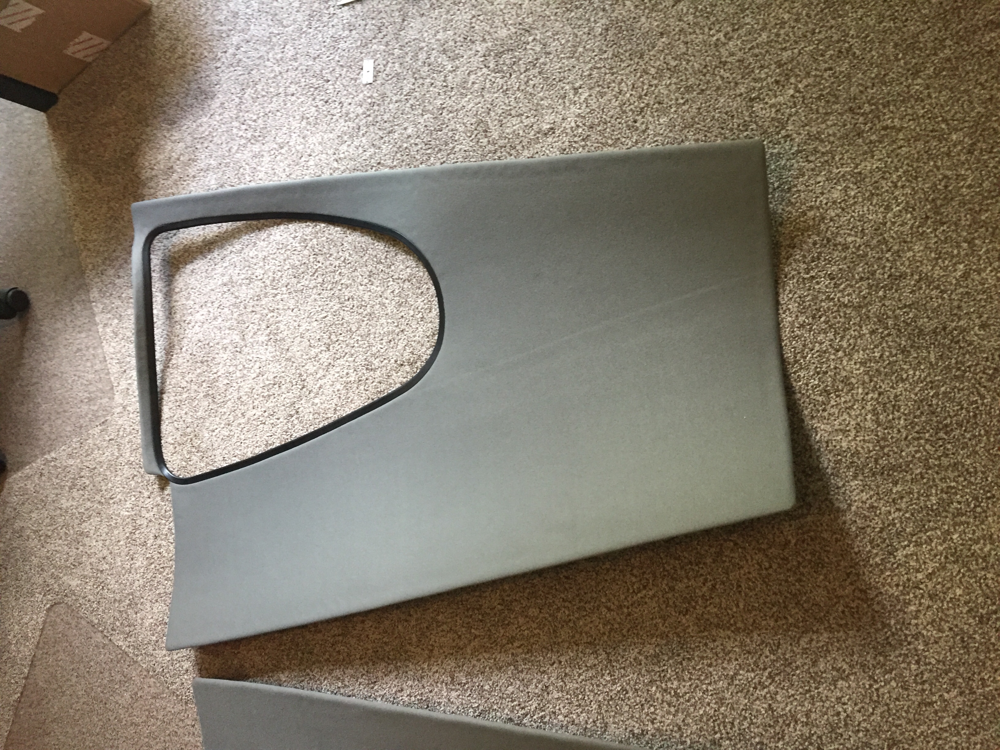
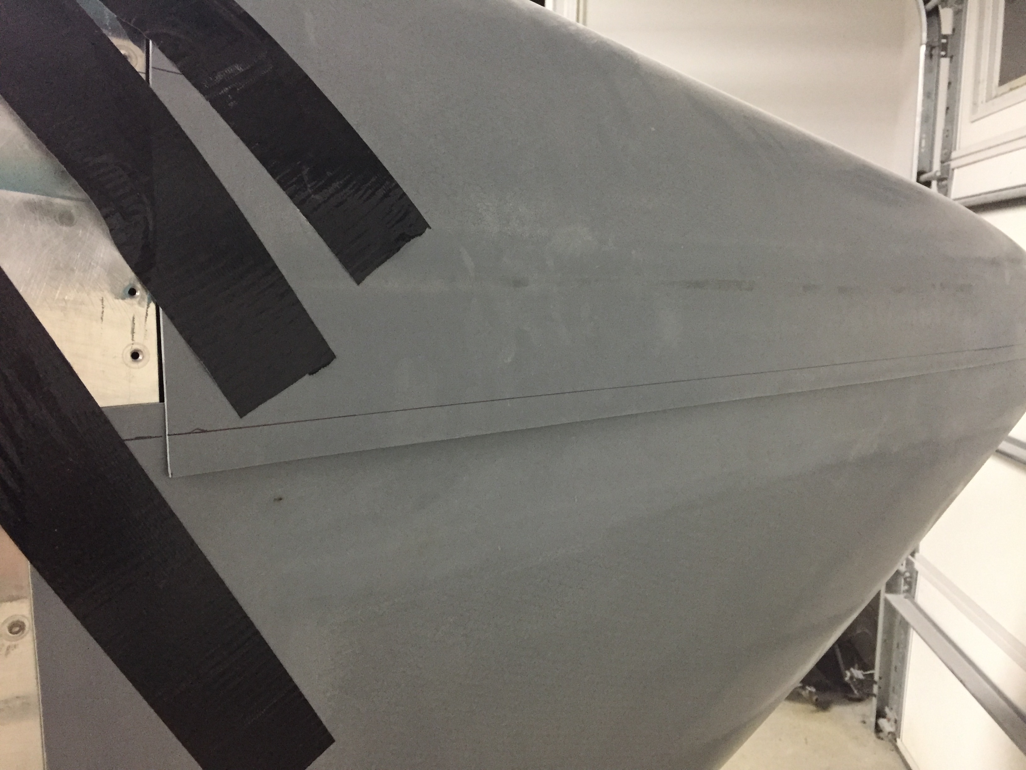
The cut came out well and a few minutes blocking it with sandpaper resulted in a nice fit.  The bottom cowl was next and needed a clearing slot cut for the nose gear leg before even rough fitting.  The Show Planes cowl has a unique fairing that I still didn’t understand quite yet but did know that I need not worry about a finished product at this stage.  I cut the opening as small as I could while giving room to put the cowl in place.

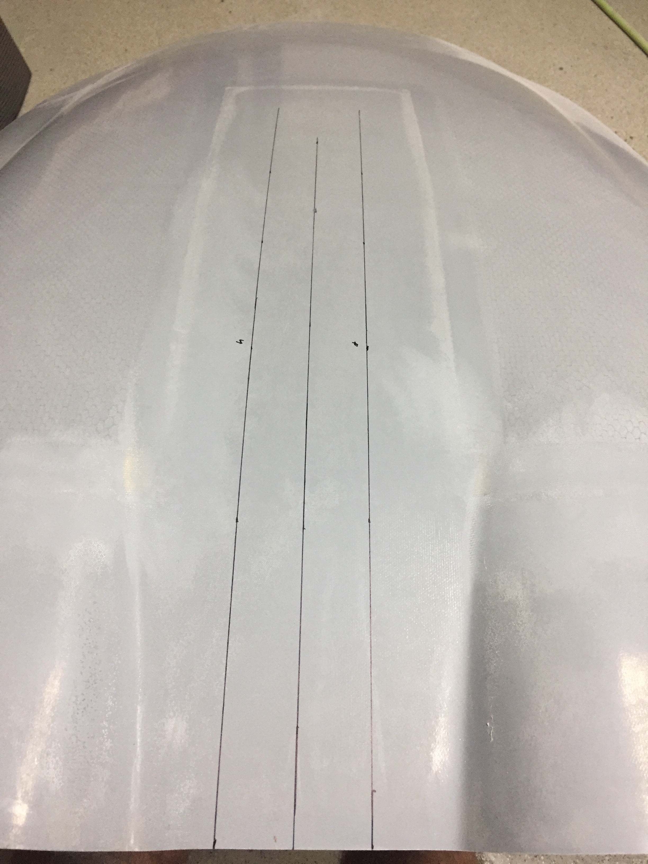
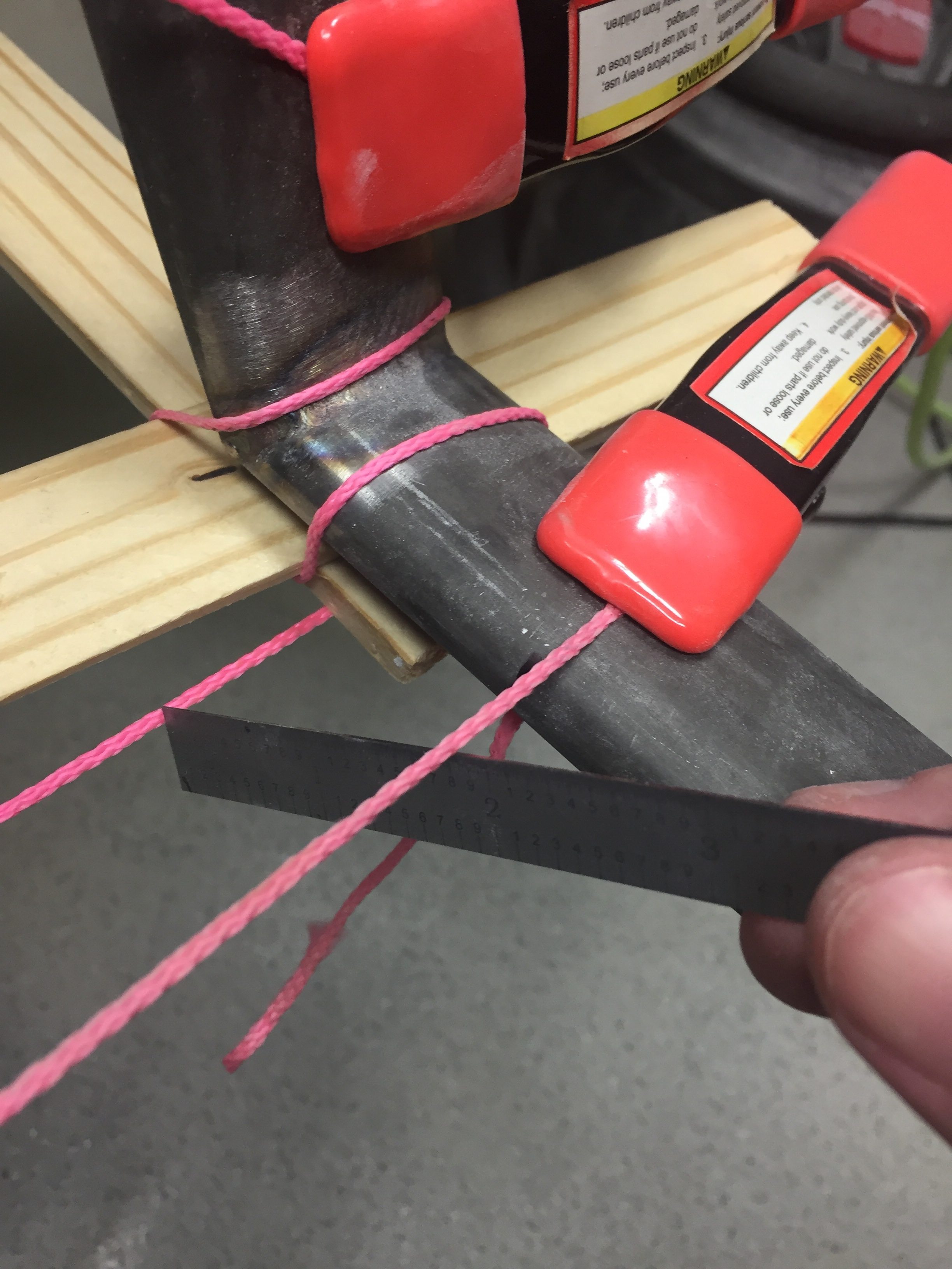
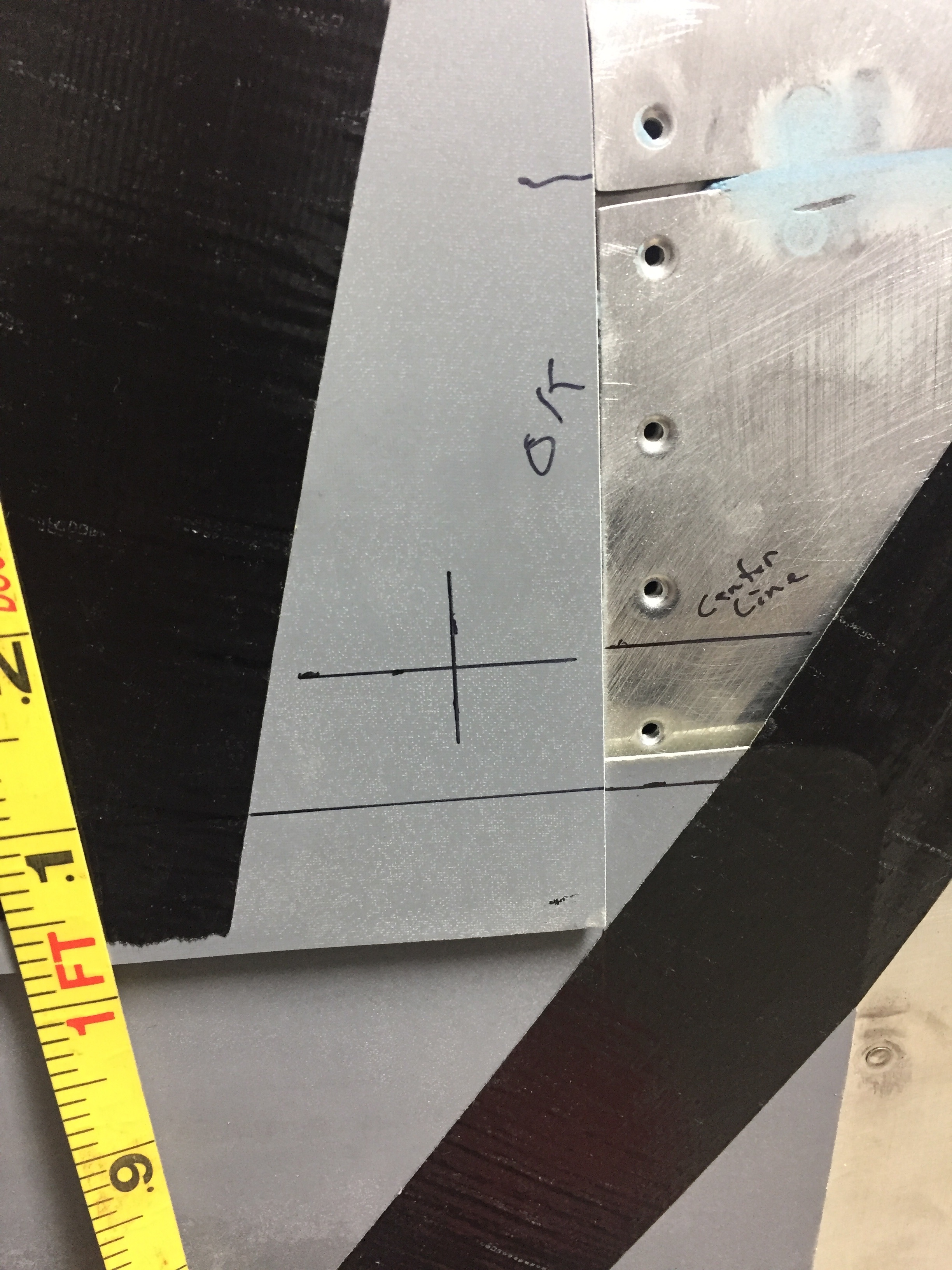
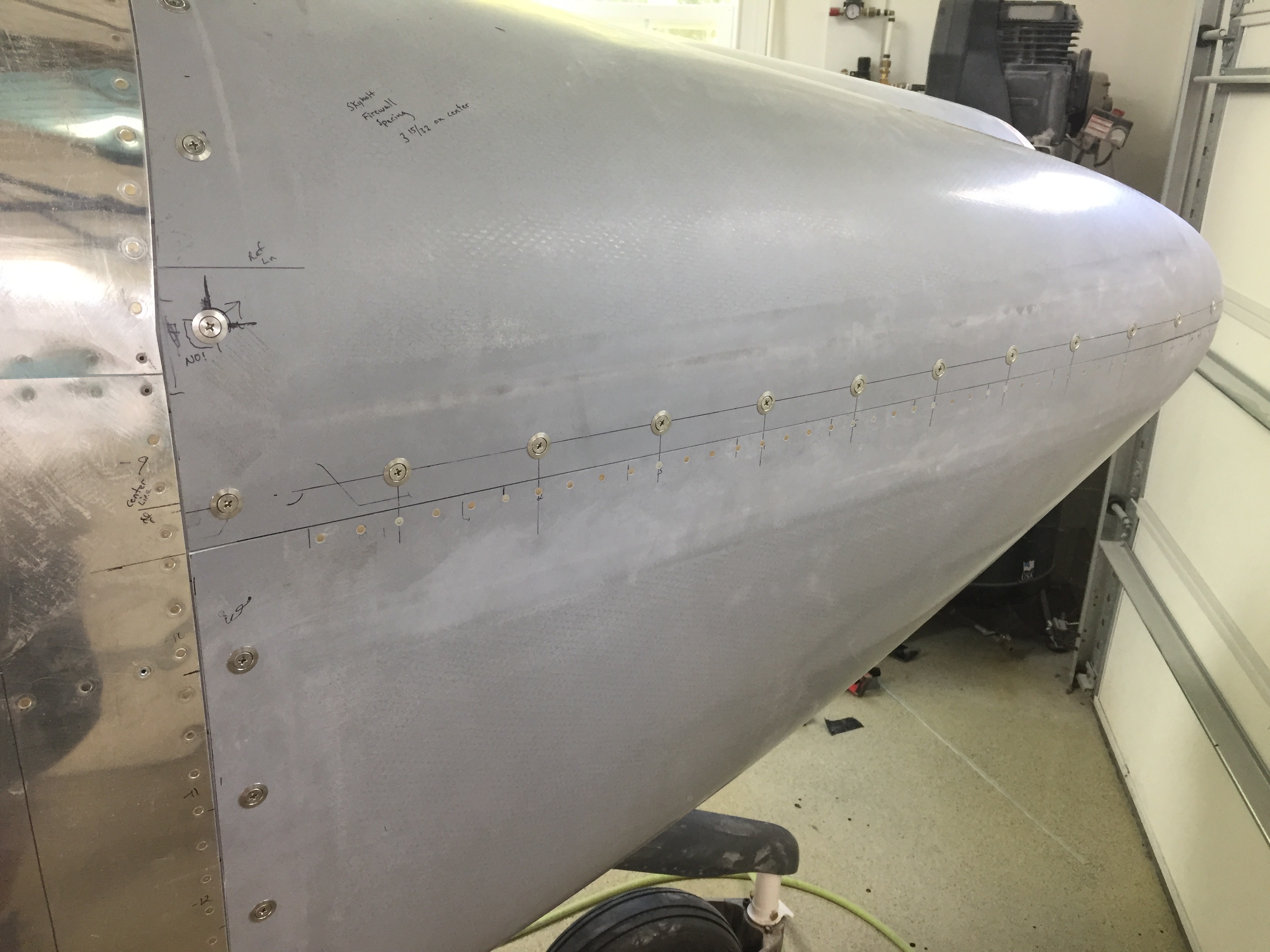
With the two halves fitted and tapped in place, I established the horizontal split line and the Sky Bolt line.  It’s key to establish where the skybolts will go on the horizontal line so that the firewall line can be even creating a nice symetric appearance.  Once the split line was figured out and marked, the bottom was similar to the top for the aft cut and soon the overlap was gone and sanded to fit with an adequate paint gap.

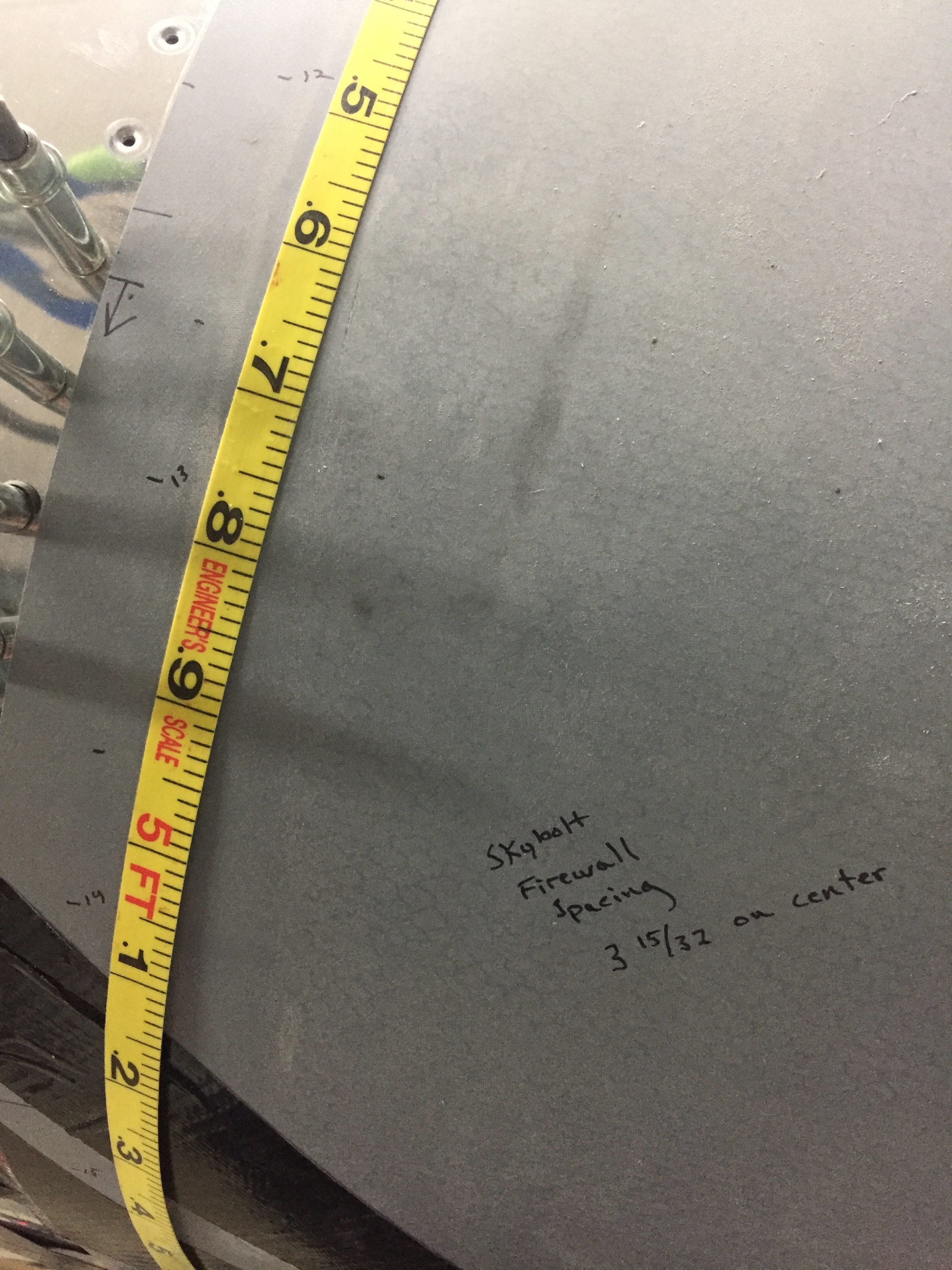
Finally, I trimmed the horizontal split line on each cowl half and used the top as the line to match with the bottom.  A bit of sanding and fitting the bottom cowl 5-6 times, and I was happy with the result.  Next up was to lay out the skybolt holes and install the brackets for the receivers.  The manual gives a target spacing that I was able to hold to pretty closely.  I started from each side’s horizonal split line placement and did a bit of math to evenly space the upper firewall bolts.  I think used the same spacing on the lower cowl each side to confirm no interference with the engine mount bolts.  It’s tight, but it works.  Lastly, the horizontal spacing was calculated and marked.  In the end, the fasteners will be in line and evenly spaced and will look great.

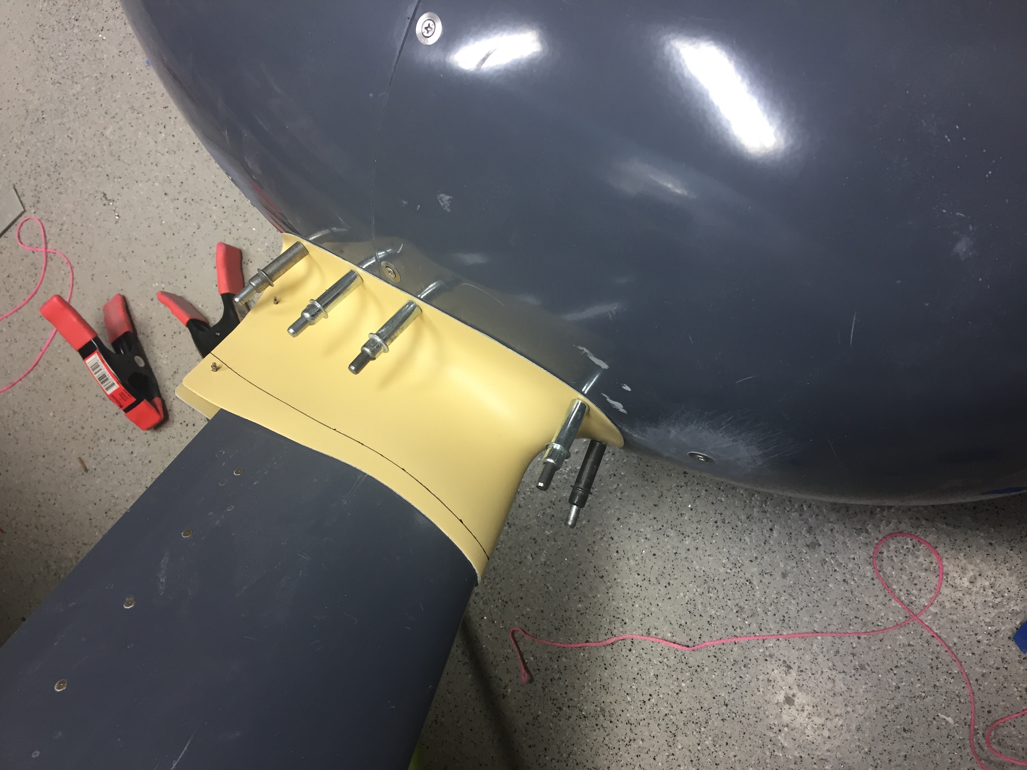
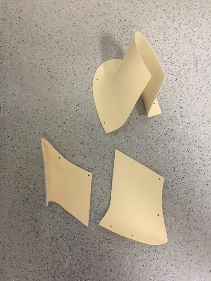
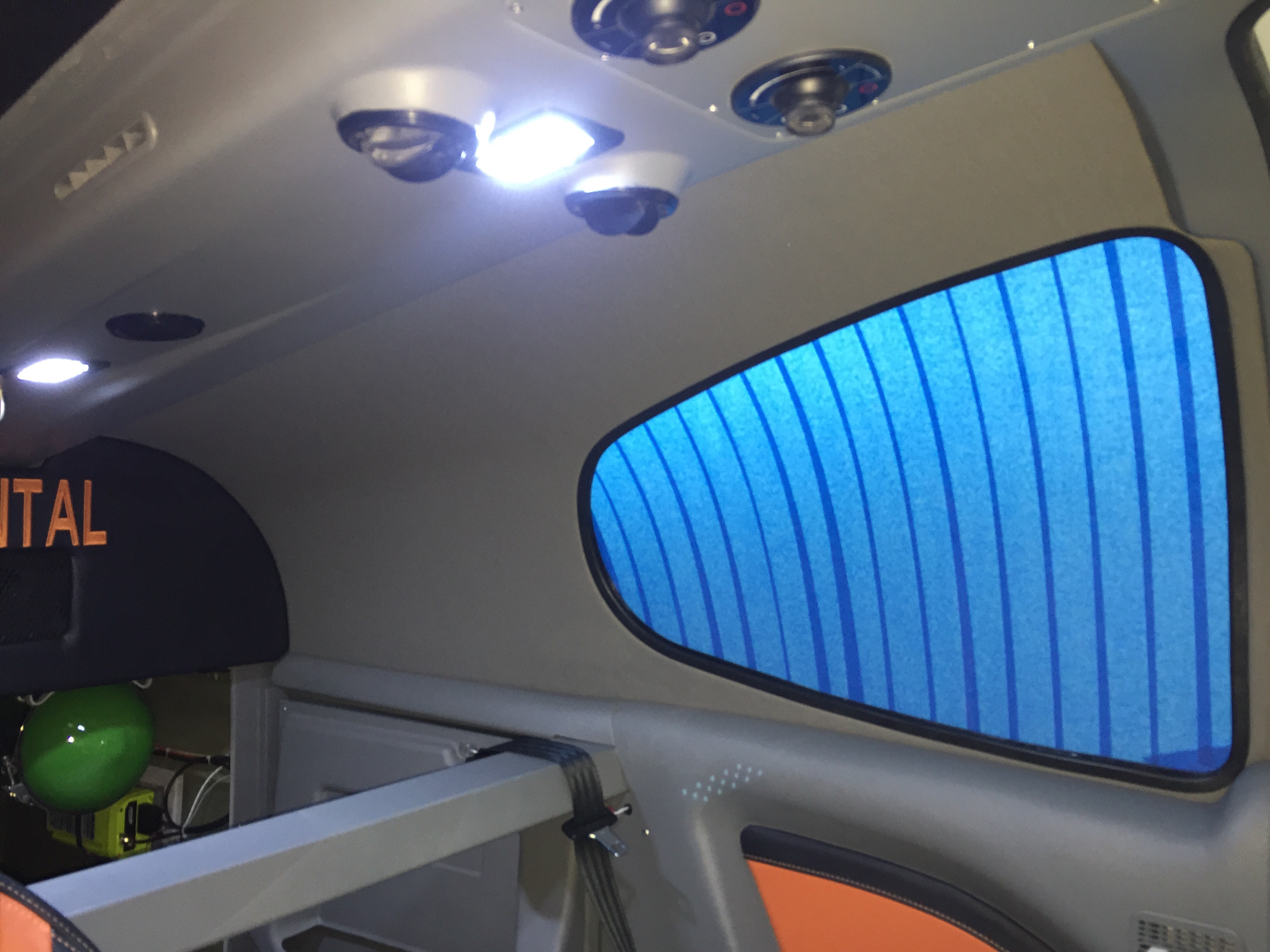
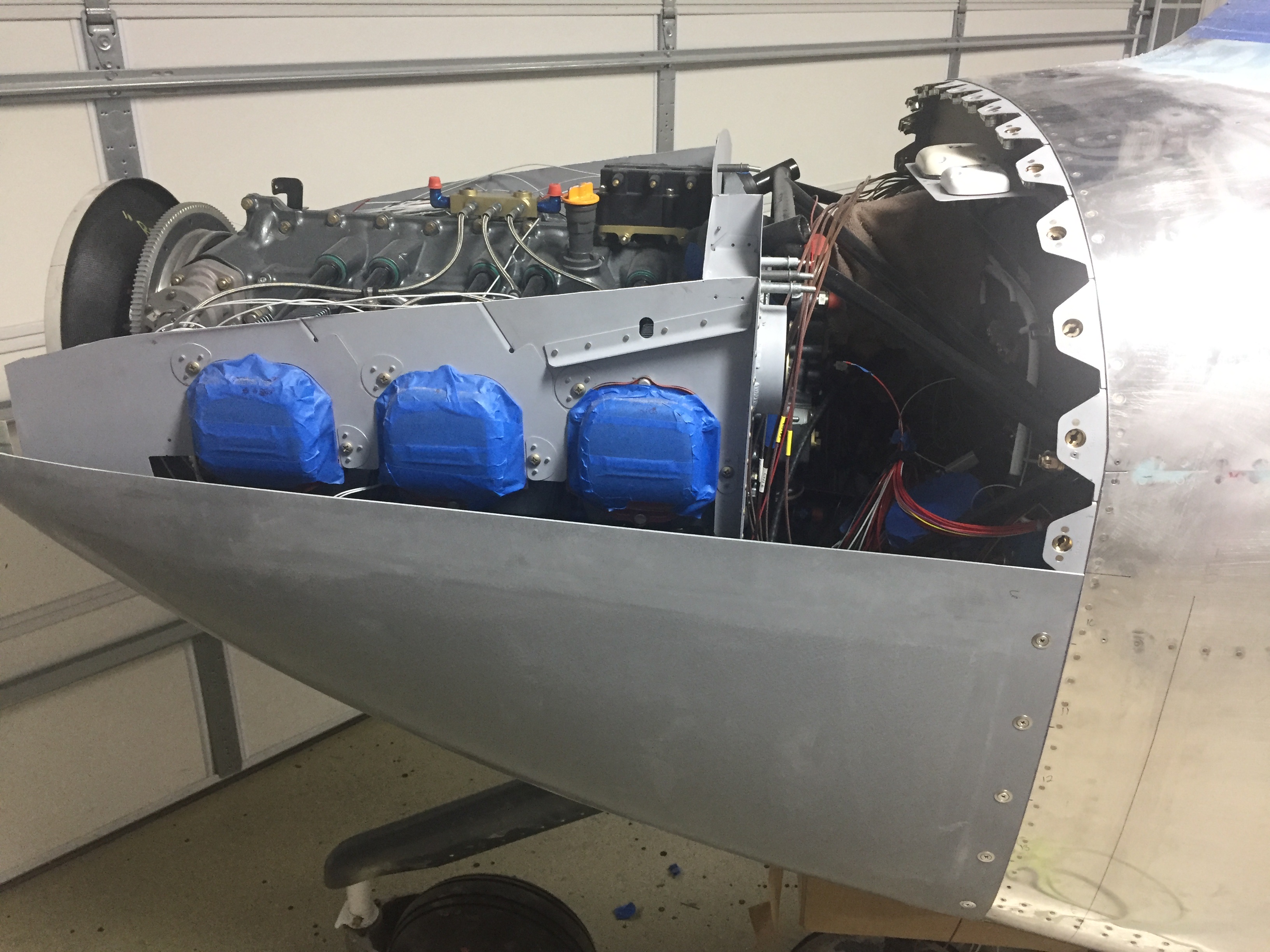
I transfered the locations onto the fuselage skin around the firewall then positioned the tabs for drilling and riveting.  Pretty soon, those were primed, shaped to match the curve, and installed.  Next step is to use drill guides to drill the initial hole through the cowl.  I thought I’d be able to use the light method from inside but with the new grey fiberglass gel coated parts from Van’s, that option doesn’t work.  I couldn’t drill from the inside using the cleco adapters, so I wound up carefully measruing and marking the centerpoint of each tab and making a #40 sized hole to get started.

Once a few holes were in, the adapters allowed the cowl to stay in place and I then used the adapters as sight gauges while progressing drilling the holes big enough to accept the skybolts.  I stopped every few increments on the step bit to check alignment with the adapters in the tabs.  It was a bit time consuming, but the process worked well and I had no issues with all of the holes.

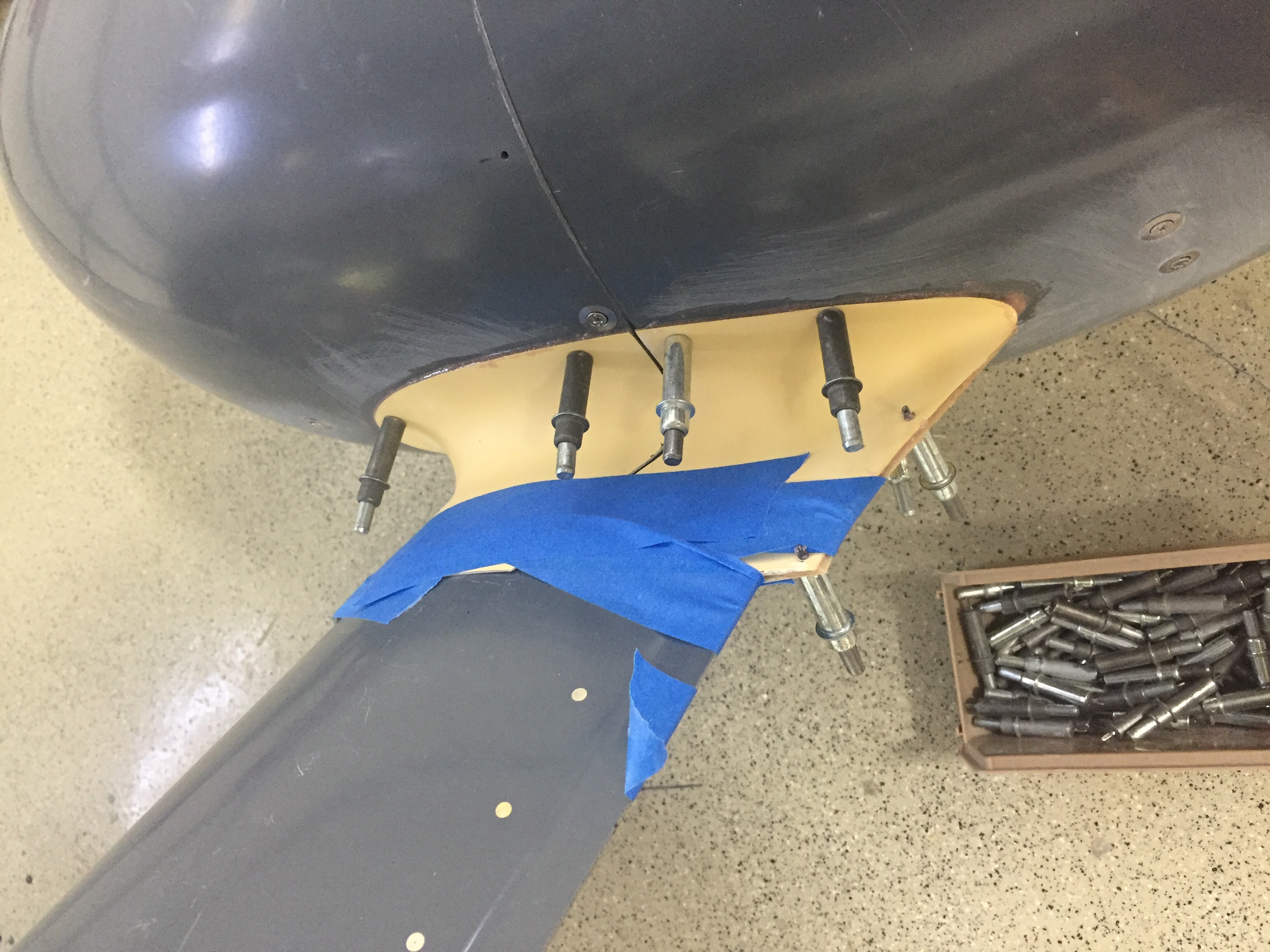
The split line fasteners were the last ones to be installed, as I used some walrus teeth (2×4) to prop the cowl in place and firewall fasteners to secure it.  Laying out the drill holes and then confirming with a #40 hole was the first step.  Unfortunately, you can’t drill progressively since you don’t have a way to hold the clecos adapters in place as sight gauges.  So I installed the tabs and then marked the centerpoint of the hole before taking time to step drill while the cowl was off the plane.  The skybolts have enough leeway to allow a small margin of error, so it worked out fine.

I’m not sure it was really that much more work than the stock method using the piano hinge, but I’m happy with the result.  It’s dirt simple to remove the cowl and I personally really like the looks of the fasteners.  They aren’t for everyone, but they are for me!

Brains and speghetti

Hanging the engine seemed like a big step, but wiring it and plumbing it is the real work.  I knew the connections to the ECUs and sensors would be a big job, but I thought the days of electrical wiring were mostly over.  Boy was I wrong!

I brought it on myself, really, as I knew using SDS would be deep in a mess of wires resembling an Olive Garden menu.  It’s absolutely worth it though, as I’ll wind up with a powerful and efficient (relatively speaking) engine with lots of tuning ability and choice of running LOP with a simple flip of a switch.

I started by screwing the ECU relay box to the ECU case itself with a few screws tapped into the ECU case.  This creates a tidy package that will bolt into the cabin side behind the subpanel.  I also put the mixture knob relay box on with double sided tape to secure everything in one palce.  I had already mounted rails with nutplates in the subpanel.

SDS supplies a harness with labeled wires and prefabed Dsub connectors.  I fished all the wires that will go firewall forward through the stainless penetration and quickly realized there was no where near enough room to run all the wires.  I still had the CHT/EGT and other EMS wires that needed to come through for the AFS EMS plus a few other misc wires.  Without regards to symmetry, I decided to scrap more of the expensive firesleeve penetration kits and just run with a silicone high temp grommet and fire stop.  The plans call for a plastic grommet and fire stop, so I’m still above minimums here.  Two more holes painfully drilled and deburred in stainless steel allowed enough room for the tangled mess.

I underestimated the amount of connections and sensors needed for everything!  It seemed the wires never stopped and I always had more hanging waiting for their turn in the spot light for a trim and terminal.  Injectors, coils, EGT, CHT, hall sensor, TPS, MAP, AFR, oil pressure, fuel pressure, original bell telephone…okay not the telephone.  I routed everything as neatly as I could keeping in mind strain releif, heat sources, and interference from other wires.  I’m sure someone could do it better or neater, but this is working for me and I’m not really trying to win a neatness contest at this point.  I chose to use zipties for now and will experiment with a 500*F rated sprial loom from McMaster Carr to clean everything up a bit down the road.

I focused on the firewall forward and finally had everything connected and pinned out.  I created a carbon fiber plate for the THREE MAP sensors, yes, three of them.  I also used Bryan at Show Planes’ transducer mounts to avoid more stuff on the firewal and create less plumbing lines.  I also worked on the spark plug wires which use MSD terminals and wires.  They were pretty easy to make up and I went ahead and drained the preservative oil out of the cylinders to install the spark plugs with the adapters and anti-seize.

I did run across my first dumb ass moment when I relized my perfectly placed EGT probes are not perfectly placed.  They are smack dab in the middle of the spark plugs and thus need to be removed to change the plugs.  Not the end of the world, but will add maintenance time down the road.  If I get tired enough of them, I’ll remove the exhaust, weld up the holes and reposition them.  Speaking of welding, I had Charlie on base weld up a mis-drilled EGT hole (interfered with the induction intake) and the AFR bung.  As always, he did an amazing job for the reasonable cost of a few cases of beer for the shop.

Fast forward a week or two, I finished the brains by working cabin side of the firewall underneath the panel.  I just love contorting my body in some ungodly yoga pose upside down while having my face inches away from my work area to work under the panel!  Fortunately, the wife came out and stood by my side as an assistant for the three hours it took me to terminate all of the extra wires inside.  I had to pin out a few switches, mixture knob, sensors, grounds, power, and signal wires for the ECUs and EMS.  It wasn’t fun, but it went well and I got all of the connections made correctly with her help and a lot of triple checking.

We also remounted the air oil separator on stand offs I created and bolted the improperly drilled holes to seal the firewall.  Mounting the ECUs was a rediculously difficult endeavor but thank goodness I had already installed the rails and nutplates.  Without those, it would have been impossible, truely.  I hope I don’t have to get those boxes out very much if ever at all.  The wiring needs some tidying up underneath that I’ll do another day but at long last, it’s all hooked up.  The final step was to fire up the master switch and check out the ECU programmer now that it is installed in the panel filling the last hole.  It’s at long last a complete instrument panel!

Hate to say it, but you’ve gained weight

About 375 pounds to be exact, all on your front end!

I enlisted the help of friend/flier/builder/neighbor Dan Olsen to help me hang this piece of art on the front end.  I had done a little prep work such as sealing a few penetrations in the firewall that would be tough to get to and removed the air oil separator, as I was pretty sure my original location would interfere with the back up alternator.

Some folks have had a lot of headache while hanging the engine while others have thrown it right on.  Overall, I’d say we were towards the later, as the engine behaved admirably and didn’t give us too much trouble.  We supported the tail of the fuselage to put the nose gear on the ground and used ratchet straps on the engine hoist so we could adjust the angle of the engine relative to the engine mount.

The top mounts went on easy, of course, and we secured the hardware enough to hold it in place.  The lower bolts were the more difficult ones, as with the dynafocal mount, the engine needs to be nested in the mount but gravity is working against you.  We found that using a easy grip clamp helped hold and compress the mounting pads enough that the bolts were able to be tapped in without much force.  It all sounds simple and easy but was 30 minutes of tough work and a lot of maneuvering tools.

Four bolts in and we have an engine!  Remarkable that all of the force, torque, and stress is secured with four bolts.  The mount modification by Barret was perfect for the cold air induction and it’s nice to have the fuselage balanced nose heavy now so no more tail stand required!  She is officially a tricycle aircraft now, not a four wheeler.

I took some extra time and used my sealant gun to really seal up the factory intercylinder baffles well.  I’ve researched and discovered this is critical to keeping cooling air traveling through the intended paths and fins which helps control CHTs in flight.  Doing it now before accessories and exhaust are mounted makes the task doable and the sealant gun with curved nozzles makes it easy.  It was actually really fun finding all the little spots to seal up and visualize where are can escape from the cooling envelope.  It also makes a lot of sense how you can not get great cooling from a stock engine and baffle setup without some extra TLC such as this.

The oil cooler was also installed and sealed carefully to maximize air efficiency through the cooler.  This is the next size up from the stock cooler and the modified mount works great without a lot of fuss.  I’m sure it could be better if I had mounted it paralell to the ground and had a nice clean duct, but folks are flying a lot with great results just as I am doing it.  The butterfly valve should help keep the oil temps higher in cold/high altitude flights that we have planned.

Baffles are up next and can be a bit of a tricky project to get completed.  There is also a well documented modification on number 6 cylinder that I’ll do to increase cooling and help reduce CHTs on that notoriously hot cylinder.  The baffle on number 5 is the hardest to fit onto the engine, so I taped up about everything to avoid or at least minimizing messing up the goregous paint job on the engine.  There are a lot of unique pieces of metal and I am awed at who ever designed the presses to stamp these things out.

Behind number 6, the fins are not deep enough to allow air to channel between the cylinder wall and the baffle.  Some have put a washer here which just pushed the baffle out a bit and allows some air to go through.  The RV-14 has a new mod where a channel is built in which provides clearance in that area, so I made the same modification to mine.  A few mockups using manilla folders, and I finalized a design which I riveted on and will seal once painted.

Once all the stock baffles are on, it was time to fit my RV Bits carbon fiber plenum.  I had this shipped all the way from South Africa and it’s a nice piece.  If someone wanted to create their own, it really wouldn’t be hard but it would take some time.  I positioned it to maximize the opening up front around the intakes but keep it clear of the cowl which should help keep the pressure higher on the cooling side.  That increases (in theory) the delta P between the high and low side of the engine as the hot air passing through the engine is sucked out the bottom of the cowl exit.  I initially drilled holes in the baffles and plenum but later redrilled the baffles after fitting the cowl (to be documented in a future post).

The Airwolf remote oil filter has a spot reserved low on the firewall near the battery box and wound up being perfectly placed.  I installed the brackets and doubler along with the fittings and tested the filter out.  The lines run up to an adapter that mounts on the accessory case and includes the vernatherm and oil temp sender.  This and a quick drain oil plug should make changing the oil a no-mess event.

Put some pants on

The last big delivery of the project arrived containing our engine in a pickled state from Aero Sport Power.  A huge thanks to the guys on base who have helped me get the deliveries and saved so much headache by avoiding home deliveries!  I loaded it on the trailer with a forklift and then got it off at home by disassembling the crate and using my engine hoist to lift it.  It worked out quite nicely and I used a few cinder blocks to rest the pallet on so I could put the hoist away.

The engine was preserved (pickled) by Aero Sport since it will be a few months before first flight.  This prevents rust and corrosion from setting in and keeps everything coated with a special rust inhibiting oil until I’m ready to fire it up.  I couldn’t help but bolt the prop governor on and start working on the aircon compressor install, as I’ve been concerned with that for some time.  We’re off to a lack luster start.  The studs for the prop governor were about 1/2″ short and had to be replaced.  My steep learning curve with threaded studs in a Lycoming equaled a four day project to remove them, but thanks to Amazon aircraft tool supply, a little heat, and a smack with a hammer (great tip Darren at Aero Sport, thanks) the studs finally backed right out.  I replaced them with longer studs which are ludicrously expensive for what they are and a week after I started, torqued the nuts on the prop governor.

The aircon compressor was another swing and miss, not surprisingly I must admit.  I knew I had an original design bracket from Flightline and wasn’t sure if everything was going to work out.  My setup moves the alternator to the port side and puts the compressor on the starboard side.  Well, the brackets don’t allow the current compressor model to line up with the flywheel grooves.  The alternator also didn’t fit at all since the Plane Power alternators have a slightly smaller case than the antient models this was designed around.  Basically, nothing worked.

Of course, I had already taken everything apart and mixed hardware which was a huge mistake.  It took me an hour to sort things out and figure out where crap went back on the engine to be in original configuration.  Another call to John and Robert Skinner to brainstorm, I decided to push the easy button and buy the newest compressor and mount from Flightline.  That cost a lot, but I just don’t have the time, resources, or skills to engineer a new bracket and have it manufactured one off.  I know his newest setup works, so I sucked it up and paid the bill.

Meanwhile, the last project to do before hanging the engine is putting some pants over the beautiful red Beringer wheels.  The wheel pants and gear leg fairings add considerable efficiency to the airframe so it’s important to get these right and rigged properly.  I’ve dreaded them and was right in doing so.  For some reason, these were just a royal pain in the ass for me.  I started by building a jig to hold the main paints.  I used a laser to get all of the level and plumb lines which sucked.  Then I cleaned the two havles up enough to joing them together which also sucked.  What really sucked was trying to get the alignment perfect and the holes drilled in the right spots.

It sucked getting up and down off the floor about 50 times an hour too.  How was aligning the pants in the jig with the airframe?  It sucked.  I dropped a centerline for the fuse and then measured from that to set the alignment.  What sucks, is the new pants from Vans are grey fiberglass gel coat so you can’t see through them.  Which is why the directions suck because they assume you can just shine a light through the pants marking the proper holes to drill.  I finally sucked it up and used a combination of careful measurements and the laser to pinpoint the locations to drill into the pants and mounting brackets.

It also sucks trying to mark the wheel area to be cut out because you essentially have to mold yourself into the concrete floor to look underneath the pant that is three inches off the ground.  I’m using SkyBolts on the wheel pants, which suck to install, but will make maintenance and access so much easier in the long run.  I had to drill out the mounting holes slowly to ensure alignment stayed true, but they came out nicely in the end.  It also sucked that I forgot my wheel pant axle stand off was an aftermarket purchase to replace the stock Vans part which – you guessed it, sucked.  The stand off was way too long (by design) but I was afraid to trim it.  Eventually, like Tess’s wheels, I put my big boy pants on and cut the damn things off to length, never looking back.

But wait, that was the easy part!  The second sucky task was to do the gear leg fairings that cover the legs and brake lines.  Hide your house cats, because you have to use about 25 yards of string through all of this.  Wrapping string around the gear leg fairings and steps, you use that to align them with the prevailing wind in flight.  I can’t even begin to describe how I did it, but it worked.  Measuring, plumb bobs, levels, digital inclimometers, string, lasers, string, and lots of painters tape and string plus some more string all sucked into one giant suck.

In the end, it was worth the work to have properly aligned and nice looking pants.  I’m often complimented on my pants, and now my airplane will be as well.  I repeated much of the process for the nose gear using the workbench and engine hoist to level the fuselage off the ground as in flight condition..  I trimmed my nose gear leg fairing a bit too much, so may add a bit more material back before paint, but it’s fine for now.  I also attached the RV Bits intersection fairings and chose to split them with the pants as others have done instead of per plans.  This does not suck and makes for a much cleaner look in my opinion.  I epoxied them in place and will finish the filler and sanding work later after initial flights to save build time now.

Phew, even writing that sucked.  Enough of that, let’s hang an engine!

Splash of color and an Oops

After returning from our trip up north, only a few days passed until we received a big package with a piece of art inside.  Our (second) propeller has arrived!  Whirl Wind delivered about a week late, but with prior coordination and communication with me so I was super excited to see what it looked like.  As chronicled earlier in the build, I purchased a propeller but decided to sell it instead of it hanging on the wall for three years before I was ready for it.  Joe Keys, you can’t have this one.  I knew I wanted another WW and the HRT blade is now a refined blade profile and is simply stunning.  Our orange was color matched and looks great with the black and nickel leading edge.  For now, the prop will go to a friend’s hangar to hang out with the wings until we move to the airport.

Adding even more color, I finished up the last of the wire bundling on the cabin sidewalls and went ahead installing the side panels with leather inserts.  They had been trimmed and painted for some time but I held off pulling them in and out until I knew I was done.  I spoke to Vic Syracuse who will be my DAR for airworthiness inspection prior to putting these in, as I wasn’t sure how open he wanted the airplane.  He advised to have it essentially flight ready except for rear pax tunnel cover (to inspect the elevator bell crank), cowling, and tunnel access panel.  This is the first time I’ve hooked up the foot well lights and I’m really pleased with the amount of light they give off.  It’s just enough for convenience while not quite enough to perform surgery on the floorboard.

Unfortunately, not all of the gods were looking favorably upon this new addition and when I closed the door, the pins interfered with the oxygen ports, thus not allowing the doors to latch properly.  Turns out I have the ports ½” too close to the door frame.  Darn.  Well, I said, a lot more than that and maybe one or tools took flight across the garage with no lasting damage.  My blood pressure through the roof due to my ignorance and stupidity of not being mindful to this interference, I weighed the options of replacing $500 panels or coming up with a patch.  I can’t make the pins shorter since they wouldn’t function correctly with the Plane Around latch mechanism.  I had already had to glue a piece on the pilot side panel and reinforce it with a bit of epoxy.  The seam was easily hidden and paint covered everything, so I was hopeful I could repeat the process.  A call to Will at Aerosport Products equaled a few scrap pieces of plastic heading my way.  An evening of creating two patches and a bit of filler, and I’m back on track.  If you look close enough to tell the patch is there, you probably won’t be flying in my airplane again; kindly go away and take your judgement with you.

Meanwhile, I applied the 3M carbon vinyl wrap on the seat pans to clean those up.  I figured out quickly paint was not going to hold up there.  Brian and Brandi had great results with the wrap material, so I figured it’s worth a shot.  I then put a strip of anti-skid tape to facilitate stepping on the seat ledge while getting in and out.  It really cleaned up the area nicely.  I also shimmed the outboard pilot seat rail, as the bracket above the gear mount was a 1/8” proud causing the rail to bend when screwed in.  Not sure what happened there, but with a few washers underneath it’s nice and straight and secure.

I quit trying to cheat the system and installed the ELT antenna on the top of the tail cone.  I tried every which way to hid that hideous monstrosity of an antenna but my conscious told me that it is probably the most important antenna on the airplane thus deserved its place per the install manual.  I’m sure it will grow on me.  The idea of burying it in the tail cone or tail fairing was tempting, but a talk with my DAR convinced me otherwise.

Continuing in the cabin, I spent an afternoon applying the headliner material to the fiberglass shells from Aerosport that had been trimmed for quite a while now.  It was a bit of a messy job with the spray adhesive, but not difficult at all.  I took my time and kept my fingers clean which resulted in a darn near perfect result.  After putting enough Velcro to hold a car upside down, the headliners slid into place and really dress up the cabin cover now.  The color matches great and was overall a lot easier than trying to smooth and paint the cabin top itself.

Finally, the rear bulkhead cover was back from Aerosport with the matching leather and embroidery.  I used Velcro to mount it to the bulkhead panel after installing a grill for the air conditioning return.  It turned out great and I’m really pleased with the fit and finish once it was all installed.  The cabin is really coming together with the rest of the rear side panels installed and inserts in place.  It’s tempting to put the carpet and seats in, but I’m holding off to keep them in good shape and clean while I finish building.

Upfront, I had an epiphany about my shotky diode and how it should be used to protect my engine bus.  The goal was to isolate the engine bus from the rest of the system such that I can turn the emergency power switch on (direct connection from battery to engine bus) and not have the electrons go to the man bus.  This essentially covers a short somewhere in the system or electrical fire behind the panel and gives me a bit of redundancy on keeping the electrically dependent engine going.  I wasn’t placing it on the proper power lead on the schematic, so it finally dawned on me it should go from the main power supply instead of the backup lead.  So, I installed it on the firewall and will work on a solid copper bar to hook everything up.

Garlic Sauce and Grape Jelly – Building an Airplane Engine

Fair warning, there are lots of pictures in this post!

My dad and I were pretty darned excited (okay my dad was REALLY excited) about spending time together building my engine. We arrived at Aero Sport Tuesday morning with donuts and were instantly welcomed as family. Maybe it was the donuts, maybe it was my dad’s flirting with the receptionist. I don’t know, but it worked. We were in. Darren turned out to be our build guy so I really had a complete experience with him and couldn’t have asked for a better mentor. He showed us the whole shop, introduced us to folks and explained some of their equipment. We made it to a back assembly room where a cart sat containing all (most) of the parts for my engine – painted, prepped, and organized. We wasted no time and dove in starting with rods on the crankshaft. Darren let dad and I do pretty much everything with a sharp eye on us over our shoulders. This is exactly what we wanted, but we learned other folks may just want to sit back and watch a master at work which is just fine too.

One thing we quickly learned was how to properly lubricate EVERYTHING in the engine. Even bolts that were getting torqued were lubricated, something I had never heard of. The Lubriplate mixed with a little STP oil turned out looking like garlic sauce from Papa Johns and we put that crap on everything, just like you would with pizza. It protects the components during assembly, keeps oxygen and therefore rust at bay until operation, and lubricates the workings of the engine during first start until oil has really gotten everywhere. Our IPI (in process inspections) were completed by Darren as he double checked our torque values and work before proceeding on. It was apparent that Darren had done this before as proven when he picked up a journal bearing and by feel recognized the parts man had pulled the wrong part number. He gave us a task and ran off to the parts counter a few rooms over to retrieve the proper items. This happened a few times and showed that they are still improving their processes but highlighted the incredible amount of experience and knowledge all the employees there have about building engines.

The crankshaft monster quickly grew with rods and pistons before the case halves went on with journal bearings and a few accessories followed by the cylinders. It’s a lot of work, but it’s remarkably simple with pretty loose tolerances hence the inherent inefficiencies compared to a modern car engine let’s say. Lycomings have been around for a long damn time and not much has changed in the design even if manufacturing tolerances have been vastly improved. By the end of the day, we had what pretty much resembled an airplane engine including the accessory case on, for the first time at least. While putting on the cold air induction, we had a fit issue with the oil screen that was immediately handled by the machine shop who bored out a recess. The right tools make any job simple. That and having the right people who know what they hell they are doing. I sometimes think I should not own a Dremel, as I think I can CNC machine things freehand.

Day two started off with a Knock It Off, as we say in the Air Force. Darren wasn’t happy with having the tach drive shaft removed since it would create a leak point on the accessory gear case and be hard to seal. Even though I don’t need the tach drive and it meant pulling the sealed/gasket-ed case off, we did the right thing and removed it. The shaft adds a few ounces but can be left unattached to anything and is now properly sealed with the bearing and oil seal. We made the quick fix and all agreed we felt better. Dad even got to play with the Loctite that resembles grape jelly in looks but not taste. This is special gasket gel that only cures in the absence of oxygen. So it forms a rock solid gasket but any excess that oozes into the internal workings of the engine won’t cause any issues before it gets caught by the filter.

We fit the push rods and rockers in the heads and learned how to properly gap the valves along with a few neat tricks with safety wire that I have taken back home to others. Other than a crazy push rod that we suspect was cut and not remarked, it all went really smoothly and by lunch the cart of parts was just a lonely empty cart! After lunch, we bolted on a few SDS accessories to shift from building to prepping for first start. Dad and I took the afternoon off while the test department hung the engine onto the Test rig which looks like an old bread truck of some kind.  I can only imagine the number of hours that thing has racked up going from their hangar to the field at the end of the runway about 1000 yards away.  They are no stranger to various engine configurations and had the sensor and control package hooked up quickly.  An old prop was bolted on and ground adjusted to that looks about right and she was ready for the next morning.

We awoke the next morning to a blustery wind bringing a chill from the mountains across the plains of western Canada.  Oh wait, this isn’t a novel.  It was freaking cold and drizzling the final morning but we braved the elements and watched the guys pre-oil the engine.  Finally, it was time to burn some avgas so we followed the truck out to the field and held our breath as the tech turned the start key for the first time.  We were warned it may not start the first time but I wasn’t too concerned about that.  Sure enough, the second start attempt resulted in a few puffs of white smoke and a low rumble of our engine running for the first time!  Lots of smiles and hugs and handshakes all around, it really was an awesome sight and sound to see something that we put so much work into start up and run like a champ.  Dad and I built an engine (with a bit of help from Darren) and it’s alive!

Laura and I hopped in the truck and got to see a bit of the magic behind the scenes as they ran through the initial checks.  Aero Sport does a few hours of running total to start the shake down and break in process.  On each subsequent start, the engine fired off within a blade or two and only minor mixture (via the SDS knob) were made to keep temps under control.  The tech said that’s typical with the rough cut universal baffle setup they have on the truck.  As exciting as it was to see it run, we were hungry and cold, so let the pros finish up with the run time and headed inside to talk with Doug about some tips for our first start and break in. 

Running the engine at high power setting and avoid ground running was the biggest piece of advice given.  A few other notes about power and rpm along with oil changes and temperature expectations were good information to have and a lot to take in.  Meanwhile, the engine was removed from the test truck and had a complete checkout including draining the oil and checking the filter – no metal!  All of our garlic sauce and grape jelly did its job.  The tech will finish bolting the accessories on and preserve it for the few more months until we are ready to start it and go flying.

All too soon, it was time to say our goodbyes to the amazing team at Aero Sport Power.  We really felt like family there after three short days and genuinely feel welcomed back at any time.  I’m really excited to have the hands on experience of building my own engine and getting an understanding of how it is assembled and operates.  It was some great father-son time as well and the memories will last long beyond first overhaul!

Random pictures: