Brake bleeding bust

First engine start is very close now with only a few punch list items left to complete. The biggest and most important item is bleeding the brakes. Other builders seem to have mixed results with this process, some knock it out in 10 minutes and others just drag their feet while landing having completely given up on ever having effective braking abilities thanks to the ridiculousness of the task. It appeared as if I was going to join the latter group.

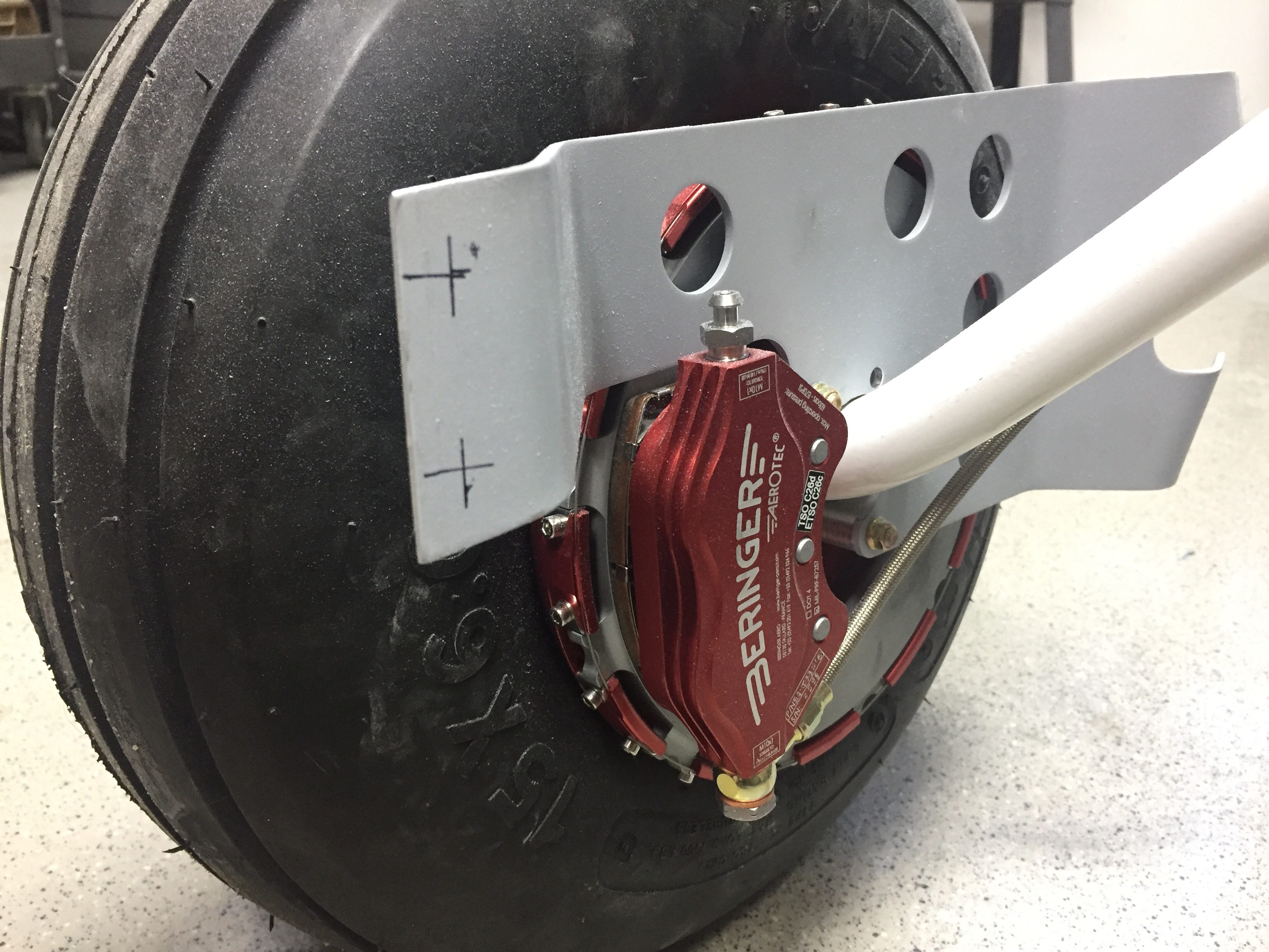
Kitplanes had a great article about bleeding from the calipers up. This makes sense as it forces all of the air out of the system as the fluid enters. One caveat for my system, however, are the Beringer master cylinders which prefer to be horizontal while bleeding to ensure the air actually escapes. That meant diving head first into the foot wells and disconnecting them from the rudder pedals. I had forgotten how many little washers and spacers were used in their assembly. Ugh.

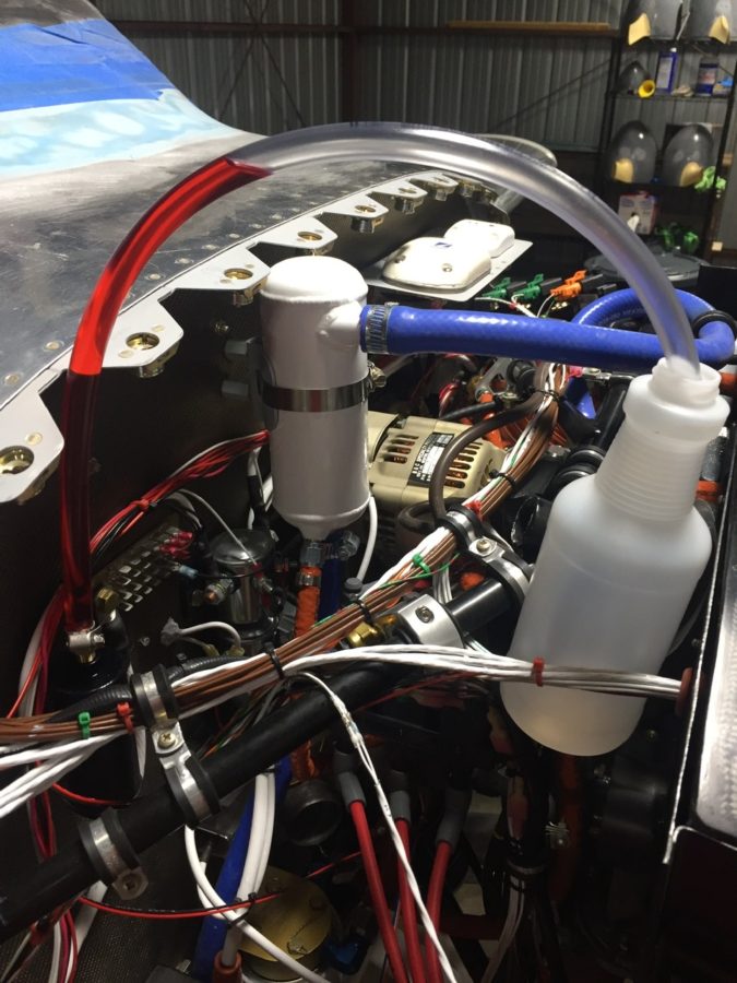
Amazon Aircraft Supply Co, Inc, LLC, R with a little circle around it, delivered a brake bleeding tank that many people recommended vs. the small hand pump bottle that doesn’t quite deliver enough pressure to complete the job. I ran down to another popular aviation hardware distribution company, Lowes, and picked up some clear tubing and a few fittings and valves. The idea is to view the fluid, bubble free, entering the caliper and then exit into the brake reservoir on the firewall. The valve allows you to control the flow of brake fluid while tightening the bleeder screw in the caliper. Pretty easy to set up and I’d highly recommend it.

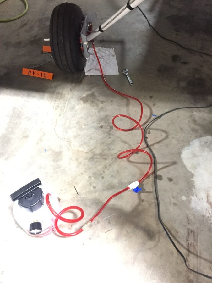
I also got a fitting to screw into the brake reservoir that accepted more of the clear tubing. When bleeding, you want to see the air come out of the reservoir followed by bubble free fluid. Once you see that, the system is bled and should have good pressure. Of course, it wasn’t that easy to get what you see below.

The right side of the system bled easily and took almost two and a half minutes. This led to a sense of cockiness and confidence that only I can exhibit while moving to the next and saying wow, this is going great! The left side brought me back to the humble earth by making a fool out of me. No matter what, we could not get the left side bled. Fluid would go in to a point but never show evidence of reaching the reservior. Likewise, we could not get adequate pressure using the master cylinder nor see any difference in the level of fluid in the reservoir. The master cylinders would also not force fluid out of the caliper as they should either. Something was wrong.

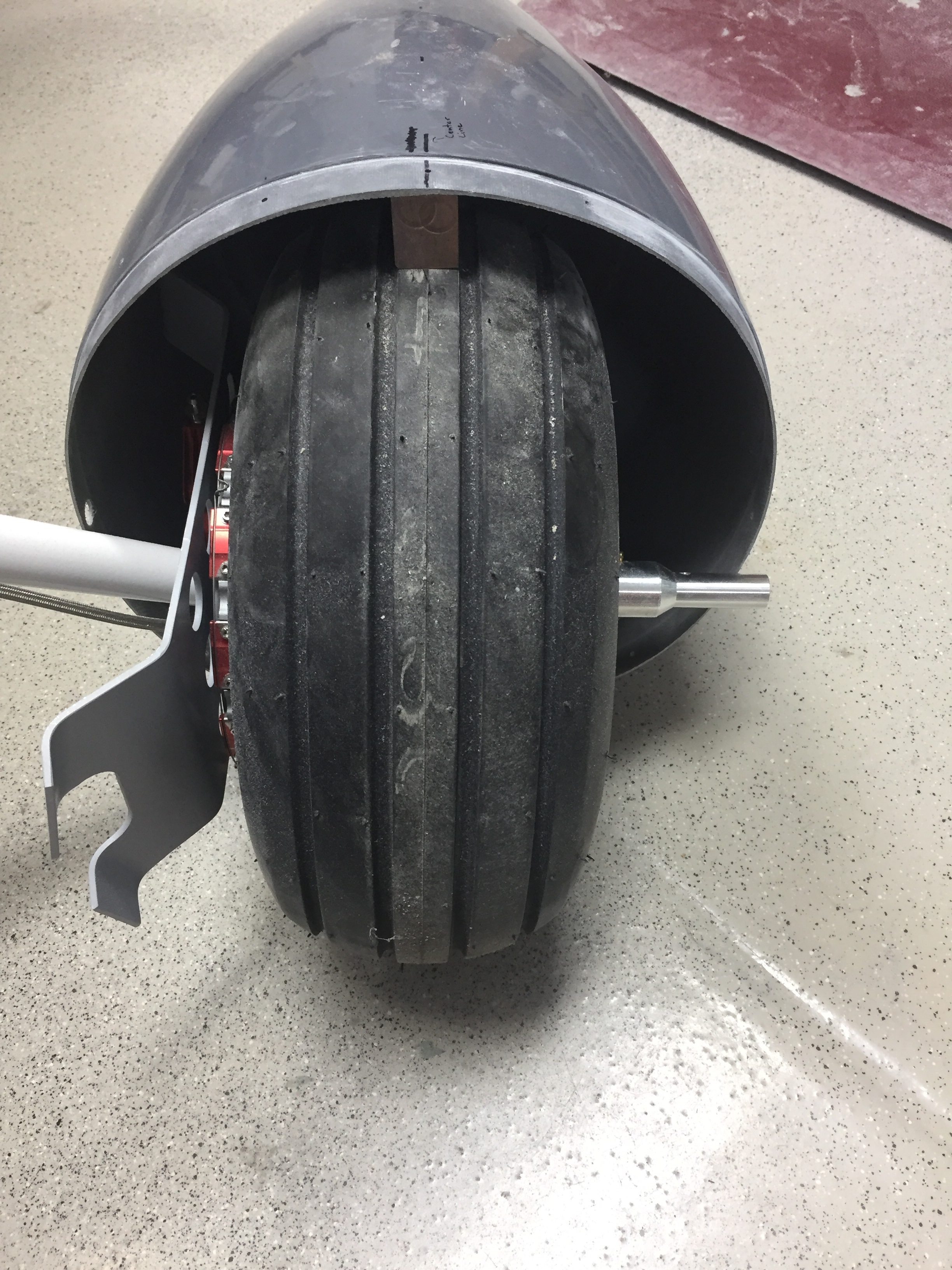
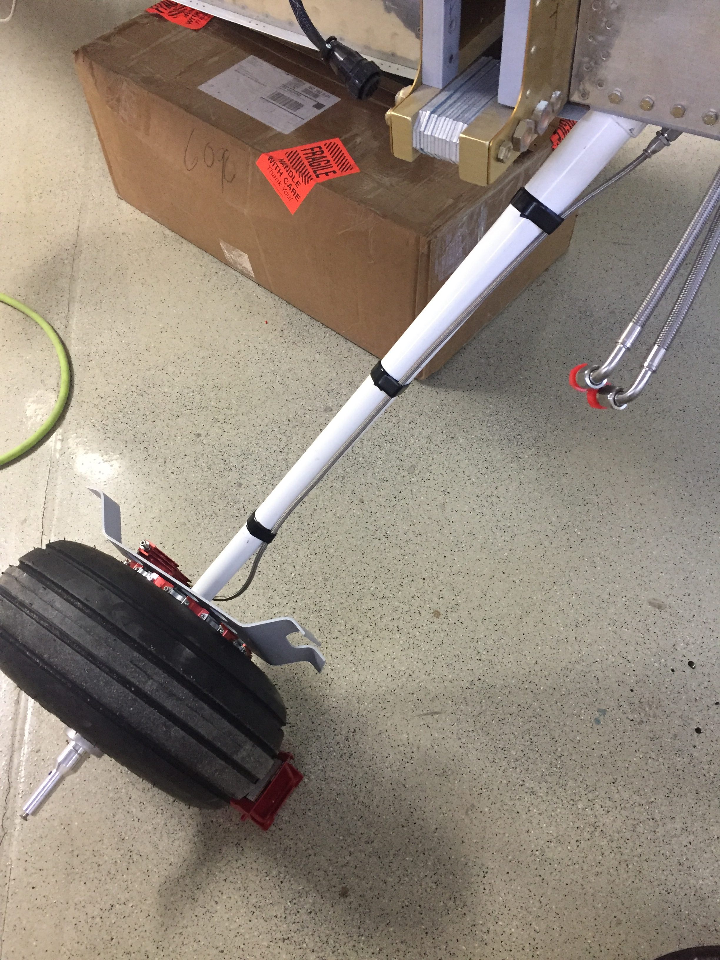
My buddy Dan, who was helping and hated the process as much as I started to, suggested breaking the seal on fittings moving up the line to see where the suspected blockage is. Fortunately, we were lucky and found it at the fitting on the bottom of the fuselage near the gear leg. Fluid moved easily up to that point but would go no further. So I disconnected the line from the tunnel to that fitting and took a closer look.

It seems that while building I neglected to cover those fittings and a little bastard insect built a fine home in that line. After taking my air hose with 100 psi set on the regulator to the hose, I wound up with this mess finally popping out of the brake line.

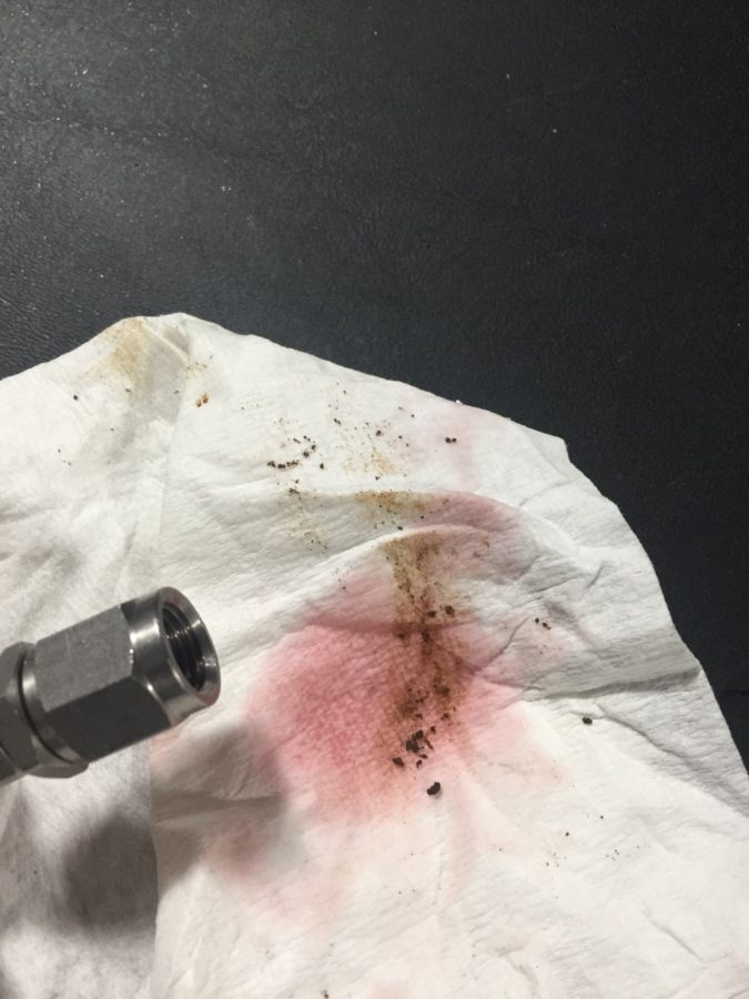
Well, that would explain why fluid would not move one way or another. After reassembling the line, it took almost two and a half minutes to bleed the left brake. This after about two hours of screwing around with it and a LOT of cussing. I also managed to piss of my hangar neighbor by telling him this wasn’t a good time for someone to come in and check out the project. Sorry dude, hope you get over me asking you for a rain check. Either way, air was replaced with fluid, the pedals were put back together with much grunting and back pain, and I could finally put the brakes on this build.

Smooth details

One of the last big fiberglass tasks is to layup the windshield fairing to the upper forward skin.  It’s a involved process with 10 layers of varying width glass strips followed up by a few coats of filler and epoxy to get it all nice and smooth.  I used cardboard to make a 7″ radius template and cut all of the fiberglass in preperation to layup the fairing.  I took other’s advice and died the epoxy black that will help create a nice finish from the inside with the Sika primer painted on the plexi.  This avoids unsightly views of the fiberglass from inside the cabin.  No pictures of the process as I had epoxy and fibers all over me, but it was a long afternoon with a lot of mixing.  I found that it was difficult to keep the layers precicely on top of each other and wound up with a few lumps and bumps along the way.  All were under the template radius, however, so could be fixed with filler.

The layup turned out pretty well and the next step is to apply filler.  I ordered a 2 mil vinyl plumping tape from Amazon Officially Approved Totally Legit Aircraft Supply Company and applied that over the electrical tape that marked the edge of the fairing.  This is probably the hardest aspect, as getting a nice smooth and even line is a bit challenging.  In the end, I did a lot of measuring and then eyeballing to get it good enough.  It probably isn’t perfect, but it looked good to my discerning eye.

My first coat of filler was the West epoxy mixed with micro to give some good ridgity over the layups.  I died it black just be be sure a good coverage again and made it good enough under the template.  After a quick sanding once dry, I used SuperFil to complete the curve which is much easier to apply and sand.  All in all, it took about five applications to get everything just the way I wanted it.  I used my favorite soft curved sanding block to sand and just judged by feel any high or low spots.  I’m happy with the turn out and I’m sure Jonathan will touch it up when he takes the plane for paint next year.

On the inside, I have one little streak of white from the tape which is a bit aggrivating, but nothing I can do about it now.  It may be covered by the side panel and glareshield, so not too worried about it, but it just annoys me.  The rest of the windscreen interior turned out absolutely perfect.  Again, the Sportsman method of taping and using Sika was a huge aspect of getting a clean finish.  It’s really cool to sit in the cabin now and look out through the windscreen!  It’s also nice having the cabing almost entirely closed in to keep it clean.

I am getting the last bits of interior from Aerosport and putting them in place as I go.  The panel inserts came with the seats and turned out great.  They are easy to install and really add a bit of class and color to the interior.  The baggage bulkhead looks great as well with the EXPERIMENTAL embroidered on the leather.  I’ll be putting a mesh grille in the cutout for the aircon return vent.

I finally got started on the wheel pants as well now the gear is on and it’s exciting pulling more parts down from storage.  I really want these pants to be finished well and have a nice fit, so I’m taking my time prepping the seams and mounting points.  I’m going to use SkyBoltz instead of traditional nutplates to allow quick removal and installation of the pants.  I don’t plan on having access doors for the valve stems because I just don’t want to do the fabrication neccessary.  This way it forces me to have a good look at the tire and brake while checking pressures monthly.  FYI the SkyBoltz are far cheaper direct than from ACS.

One issue I had to pause on and get some help was the wheel pant spacer that bolts onto the wheel nut for the main gear.  On initial fit, it’s proving to be way too long and I was hesitant to cut it allowing the rear portion of the pant to fit.  Beringer says trim away, however, so I think it’ll actually save me a few steps later in the process since I’ll be able to trim at a precise angle to match the pant and avoid using flox to build up a flange on the inside of the pant.

Meanwhile, I fabricated the last of the stainless steel brake lines and installed them to the calipers.  I am now considering swapping the calipers from side to side which will put the bleeder nipple on the bottom.  I’ve always had the nipple on the top of the calipers, but using a pressure bottle to bleed the brakes from the calipers up will allow the air to be pushed up naturally instead of forcing it down and the nipples should be the lowest point in the system for this.  If the lines can still be used, I’ll swap them.

Next up is some exciting stuff as we jet off for vacation and engine build school in Kamloops, BC.  Stay tuned for details!

She’s got legs!

I continue to empty my parts inventory which is nice to give the space back to what it should be such as guest bedroom and bonus room upstairs.  A big chunk of floor space has been taken up by the windscreen.  Now, the story is I received my order from Cee Baileys many months ago but the box was damaged and the thoughtful FedEx driver decided to take the bundled plexi out of the damaged box and simply lay on the diamond plate steel floor before continuing the route.  Needless to say, my brand new windscreen was no longer brand new.  It’s not to say that it’s ruined, it just didn’t meet my standards.  I was lucky to only have a few tiny nicks that won’t even show up on a camera picture, but are visible if you look hard enough.  A claim and call back to Cee Baileys had a replacement in a better box on the way to me.  I plan to sell the original one at a good discount and it may work for someone building on a budget or as a repair, who knows.  Either way, my fuselage was ready for a windscreen.

I prepped it just as I did on the windows and since I had already rough trimmed it, I was able to get the final fitment completed in just one evening.  I’ll be using a mix of methods to install it, following the plans on the lower edge and using the Sikaflex method around the cabin top.  I again traced the edge of the cabin top onto the plexi so I could tape it using the sportsman method.  It was actually easier since I only had half the area needing taped.

I also ground down the two side corners of the plexi to allow a nice flat surface once the fiberglass layup is applied.  I’ve seen and heard others having a buldge on either side of the fuselage and most women find buldges unsightly and moderately annoying.  This is all about impressing the ladies, so no buldges on Tess!  I decided to apply the Sika primer on the outside of the bottom area to help hide the fiberglass overlay.  I also have black die for the epoxy.  Once the skin was roughed up, I laid a good bead of Sikaflex down and Laura helped me set the screen in place.

I worked quickly again to put the wing nut clecos in and level out the screen to the cabin top.  It went well and soon enough it was time to clean up the inside.  Again, time spent prepping the tape proved to be priceless, as the inside of the screen came out perfect and professional looking.  I didn’t have any sealant on the plexi at all nor did any get on the cabin interior paint.  All in all, I’m really pleased with it.  Once the Sika cures, I’ll start on the fiberglass fairing at the bottom.  Again, the Sika will fill in the gap around the rest of the windscreen after paint is completed.

The next project and main goal before the engine arrives this summer is to get her up on the landing gear.  I bought a fancy Harbor Freight engine hoist to assist in the task and after some usualy frustration at assembling a HF tool, it was ready to roll.  I had a friend who’s building a Glasair come over and help with the lifting of the fuselage.  It was nice to have a extra set of hands besides Laura’s and my own.  He hooked up the chains on the engine mount as I padded a workbench and got the components ready.  The lift was really a non-event but nerve wracking none the less to see the fuselage hanging in mid air!

I had already built up the brake calipers and wheel pant mounts to be ready for the install and to be able to do that on the bench vs on the floor.  With the Beringer setup, a lot of the setup is different but ends with the same result.  The spacers are all machined and an extra hole has to be drilled in the wheel pant mount.  A larger hollow axle slides over the stock axle area and a pin is used instead of a through bolt.  The Beringer items are such quality and fit great.  I did have to dremel a bit of the pant mount to clear the gear leg since it’s slide inboard a little bit.

The left leg put up a bit of a fight, as I didn’t sand down the edge of the powdercoat so it didn’t want to slide all the way into the mount.  Once I figured that out, I made sure not to learn from it and pressed on drilling the hole for the bolt.  Yet again, very anti-climactic for such a momentous achievement!  We slid the main wheels on and lowered it down onto the gear for the first time.

The nose gear leg was bolted on pretty easily and we were ready to compress the pucks/strut to get the cap and bolt on next.  Remember when I said I was sure to not learn from the powdercoat edge?  Yeah, we spun our wheels and cranked on ratchet straps for an hour with no luck getting the strut cap to aling properly.  Clearing my head for an hour to go get more tools helped me finally learn and the lightbulb popped on to sand the strut a bit.  The cap fell into place easily after that and didn’t require nearly as much compression as we had initially put on the gear leg.

The next bit of ignorance on my part came in putting the bolt through the cap.  The plans called for it to be inserted from the starboard side.  I thought, it doesn’t matter.  Well, Tim, it does matter.  Follow the plans!  The hole is slightly twisted to clear the heat vents.  I wound up getting it in from the port side but made it difficult for myself.

With that complete, the nose wheel went on and she now has her legs under her!  The Beringer wheels look amazing, too bad they will be hidden under wheel pants.  I left the tail stand on until the engine is hung but still had to chalk the mains since it rolls so easily!  I took advantage of the new mobility to roll Tess outside for some sunshine and a good shop cleaning.

Staying in the lines

Throughout this progress, I’ve been finishing up the brake lines.  I ordered extra line for the run from the firewall to the gear legs and got them all fabricated.  The lines weren’t hard to make, but it was a bit tedious.  I am happy with the end result, however, and think that it will provide many years of great performance without having to worry about replacing tubes.  I do need to get some spiral line wrap to prevent chafing and that will allow the lines to be a bit better secured.  Mark Ciglia put his parking break valve in place of the firewall connections, which I’m mad I didn’t think about.  It makes it a bit cleaner and eliminates one extra set of lines, but oh well.  It’d cost more now to redo it.  Note to other builders!

I also knocked out a few little projects, one being making new elevator trim bracket panels.  I had the beefed up fittings sitting in the parts bin and finally ordered the new access panels.  After countersinking and priming, the parts are ready to roll and comply with a SB from Van’s from many years ago.  This is a common upgrade and an easy one at that.

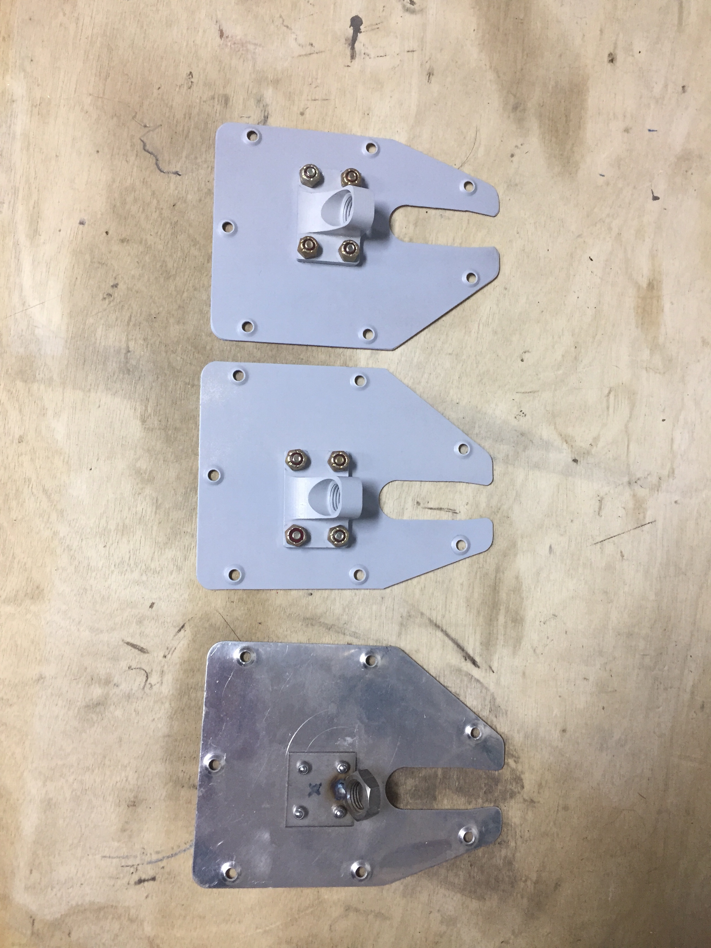
Another little project wasn’t so little.  I saved up a few tasks that needed to be completed inside the tail cone for one evening so I would only be crawling back there once (this time).  The first was to support the tail better.  I used two 1×4’s to bolt to the horizontal stabilizer mounts and put a caster on the bottom.  While the fuselage cradle has been great, the rear support isn’t far enough back to support my weight so far aft without something heavy like an engine hanging off the front.  So this was an easy fix and doesn’t take any room up in the shop.  It’s still very easy to roll around and reposition as needed.

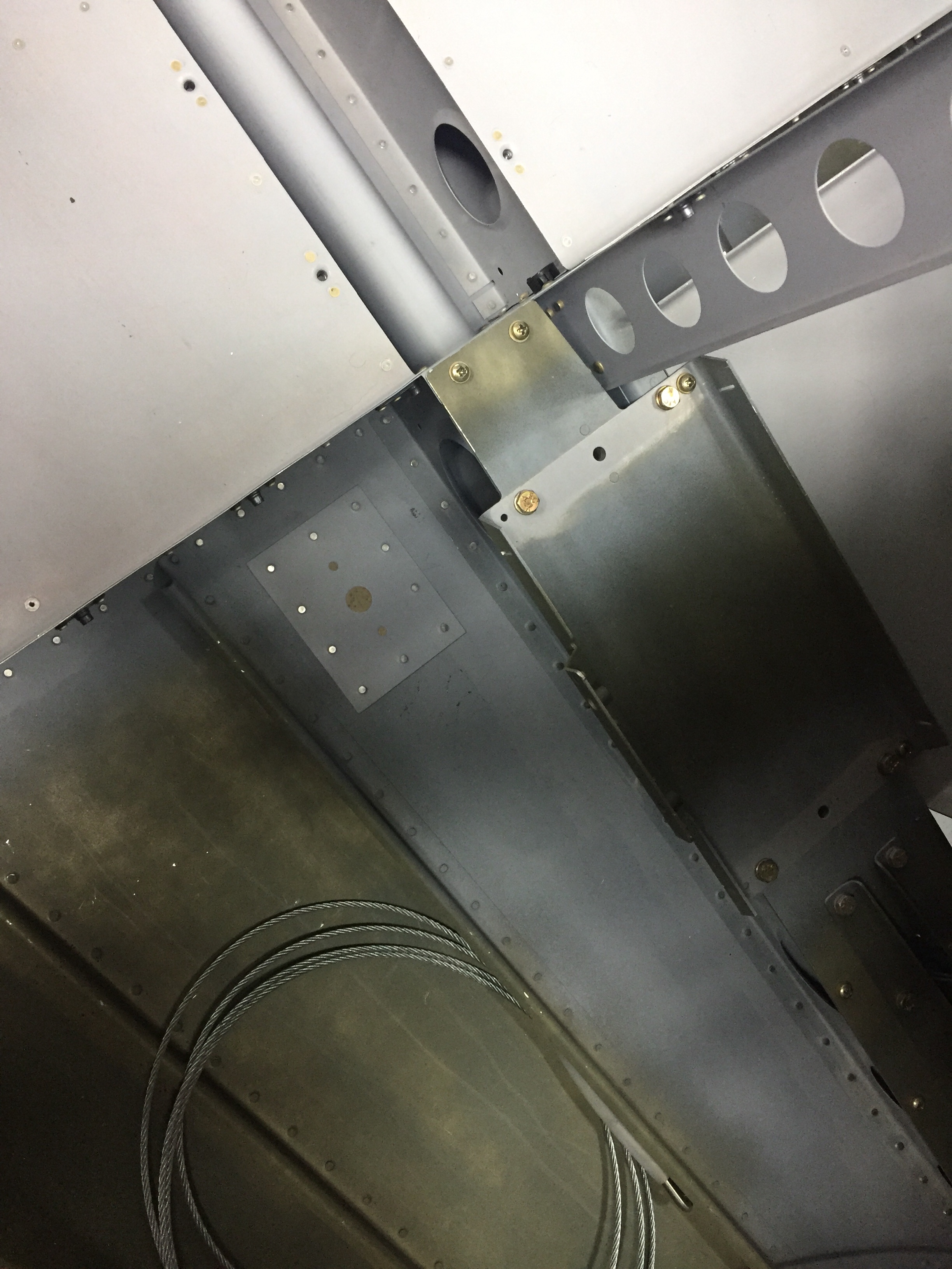
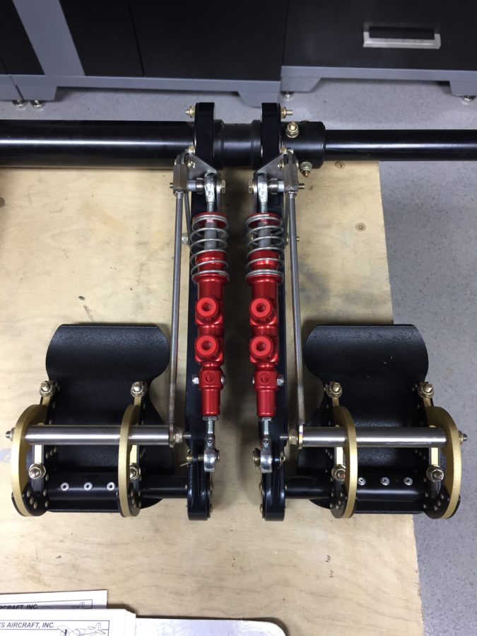
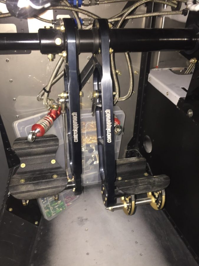
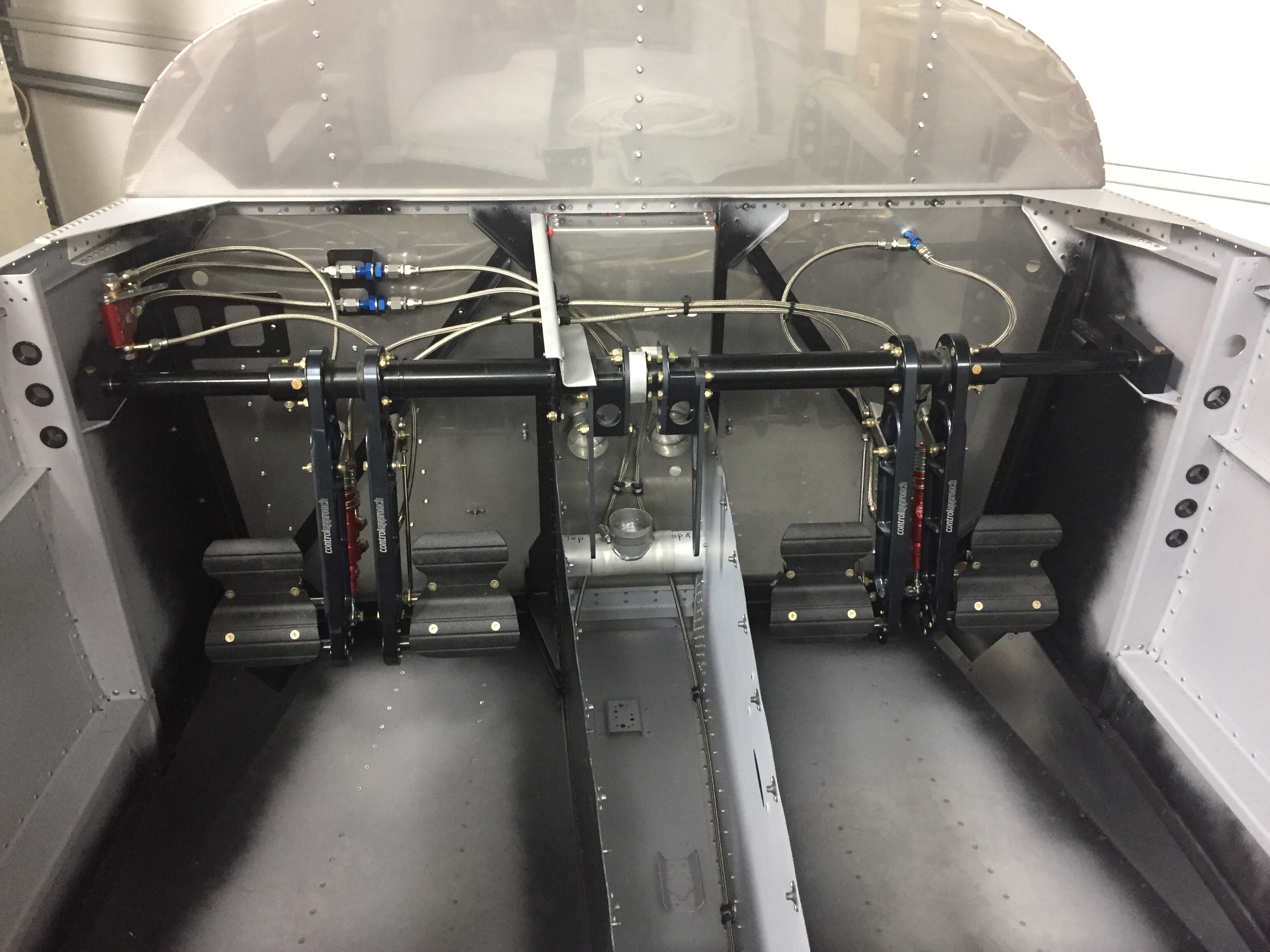
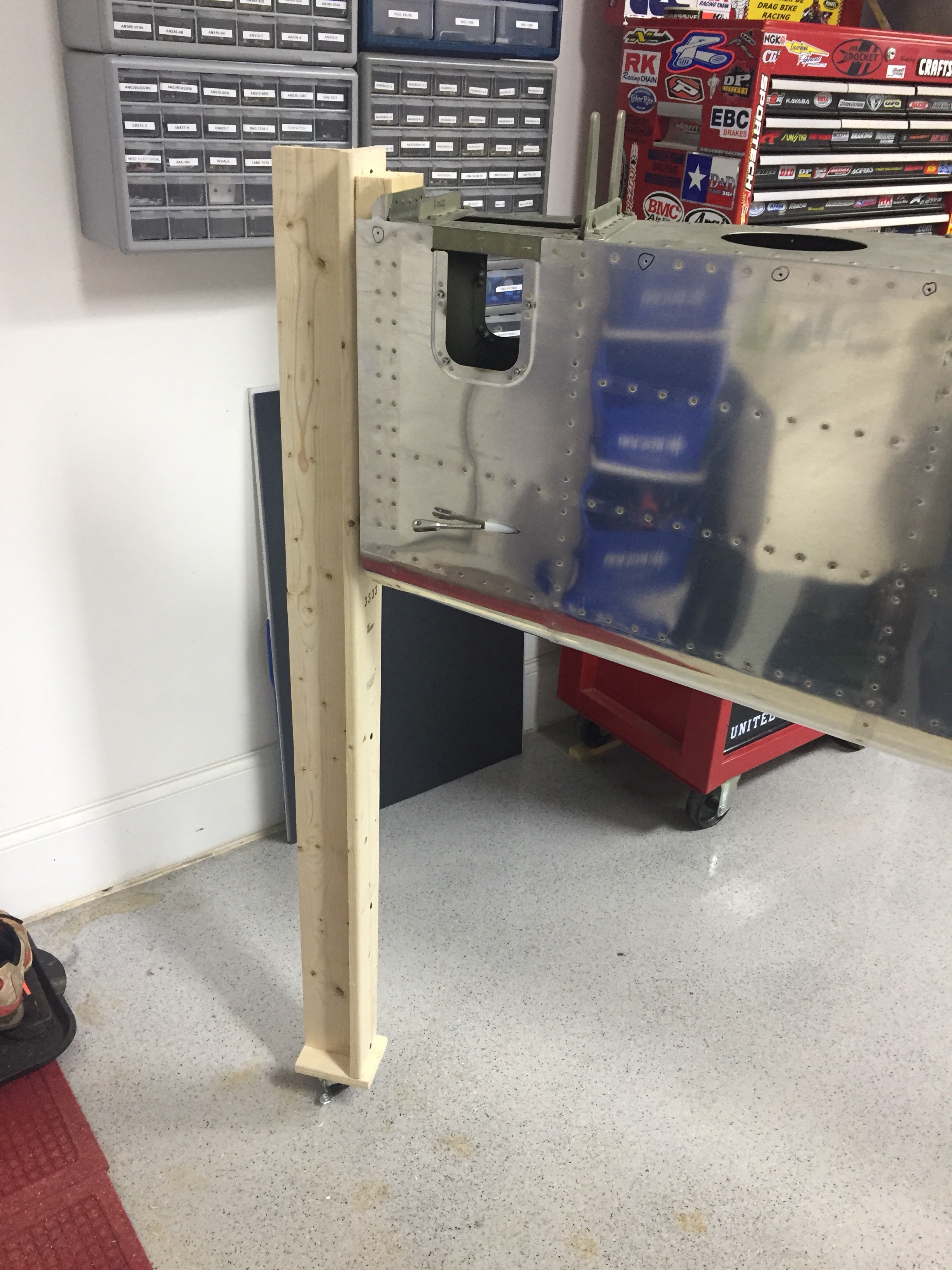
Inside the tail cone, I mounted the new static ports with pro-seal (no rivets this time) and hooked up static line that runs to where the ADAHRS will be mounted just behind the baggage bulkhead.  The new static ports look way better than the original ones and I’m happy I made the change.  The Safe Air 1 line kit makes it easy to run the tubing and create a leak free system.  I also ran the rudder cables through the bulkheads and snap bushings.  Ironically, the heads of the cables wouldn’t fit through the bushings without removing them and squeezing a bit.  So basically, the cables were a pain to run instead of a quick two minute job.  Lots of those in the build, I guess.   I got them hooked to the arms on the rudder pedals which are inside the tunnel with the Control Approach pedals.   With the A/C in there, it’s a tight fit for me!

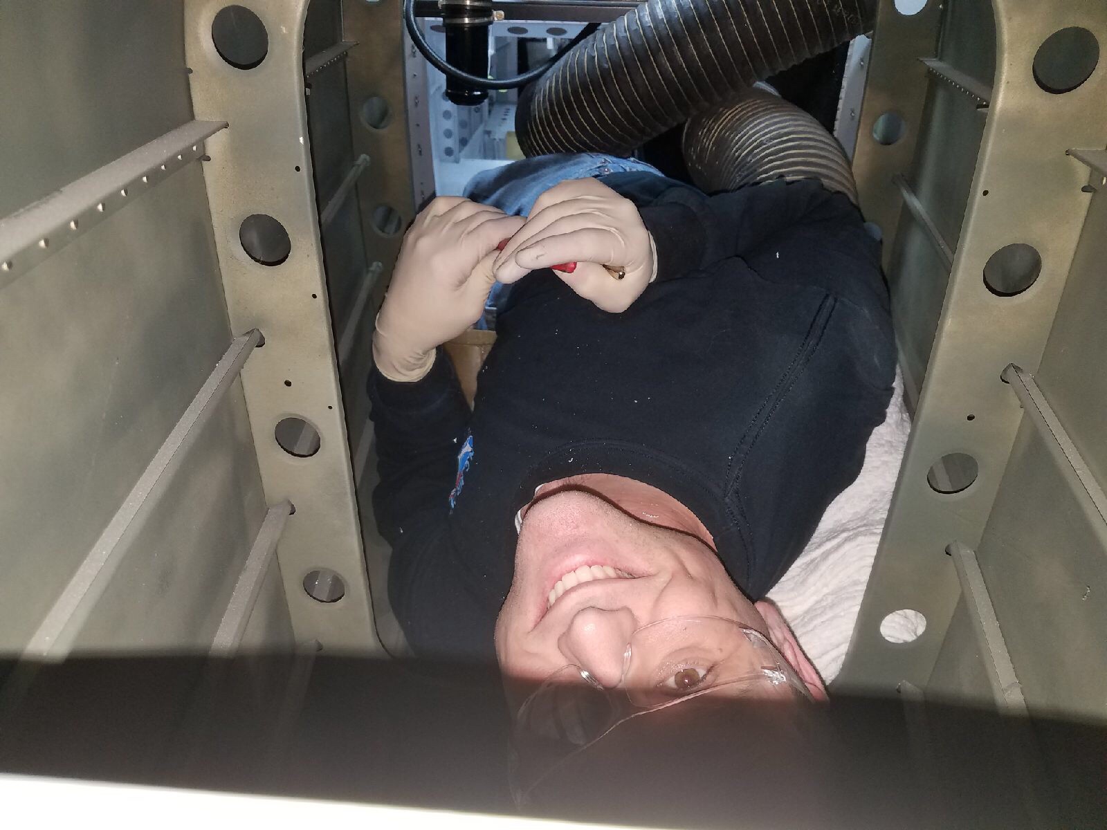
Lastly, I installed the doublers along the center of the fuselage for the transponder and ADS-B antennas to mount to.  These will be Delta Pop blades and mount with two studs, so I need access from the tunnel / fuselage.  Easy enough with a second set of hands to man the gun and me bucking.

Whoa, put the brakes on

It’s finally time to pull another beautiful piece of art work off the wall and turn it into an airplane.  The rudder pedals were next up in the plans and since I have the Control Approach set, it was a pretty quick fit in the fuselage.  I had to spend some time sanding down the tubes to fit into the mounting blocks to allow free but slop-free movement.  I also cleaned up the installation of the Beringer master cylinders on the pedals using some AN bolts and nuts instead of cotter pins.  This took some play out of the pedals while still allowing for free movement of all the components.

Before I put the pedal assembly in place for good, I wanted to paint the interior where the Aerosport panels may not cover the structure.  Per the plans, now is the time to paint the interior of the cabin.  With the Aerosport kit covering most areas, I won’t be painting all of the aluminum.  I also chose not to paint the stainless steel or put any insulation on the cabin side of the firewall but did mask off and paint the aluminum components on the firewall and the very forward area of the side panels.  90% of the work for painting is prep and it took a solid hour to mask off all of the firewall just for a few spots of color.  I’ll have a separate post about color and paint coming up.

It’s also time to start running brake and fuel lines.  Since I have the complete Beringer kit, I started fabricating the stainless braided lines.  The Beringer kit includes some really nice components and saves a lot of weight while providing a more effective braking action.  Sadly, it lacks a lot of detail in the instructions and was missing quite a few pieces.   The kit doesn’t include an inventory, so I wasn’t really sure what I had or didn’t have until I started putting it all together.  Another 10 builder reported the same issue and I believe they are working to improve the kit contents.  I will say that the customer service has been extremely swift and really pleasant.  All the missing items were shipped the same day I called along with a few extras that I ordered.  One disappointment is the use of the rigid tubing retained per plans between the firewall bracket and gear legs (the tube runs through the tunnel and under the seats).  I wanted all SS braided line so ordered extra hose and a few fittings that I needed.

The process is pretty simple to assemble the lines and the quality of the fittings instills confidence of a leak free system if I’m doing it correctly!  Time and tests will tell later in the build.  I am shortening most of the lines, as the Beringer plans have them conservatively long which actually create some routing / securing issues.  For now, I am holding off mounting the reservoir since I’ll be putting insulation on the forward side of the firewall.