Have I mentioned there are a lot of wires in my plane? Well, there are. Compared to others, I’m on par or above average on the amount of wires. I know my amount is a bit higher due to the aircon and using a single ground location, eliminating local air frame grounding. I chose to do this to avoid noise (hopefully) and chasing grounds around. Wire is cheap and relatively light (I’m not pinching pounds here) so why not? I also have a lot of interior and exterior lighting which adds more runs.
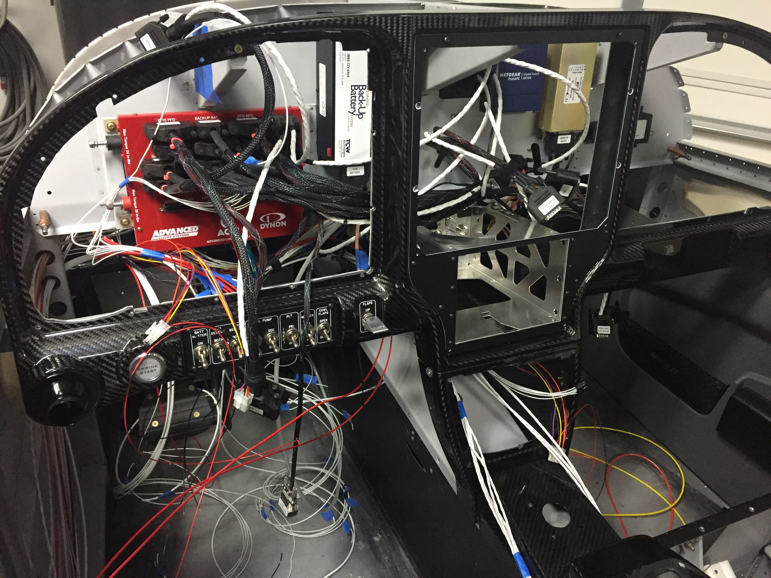
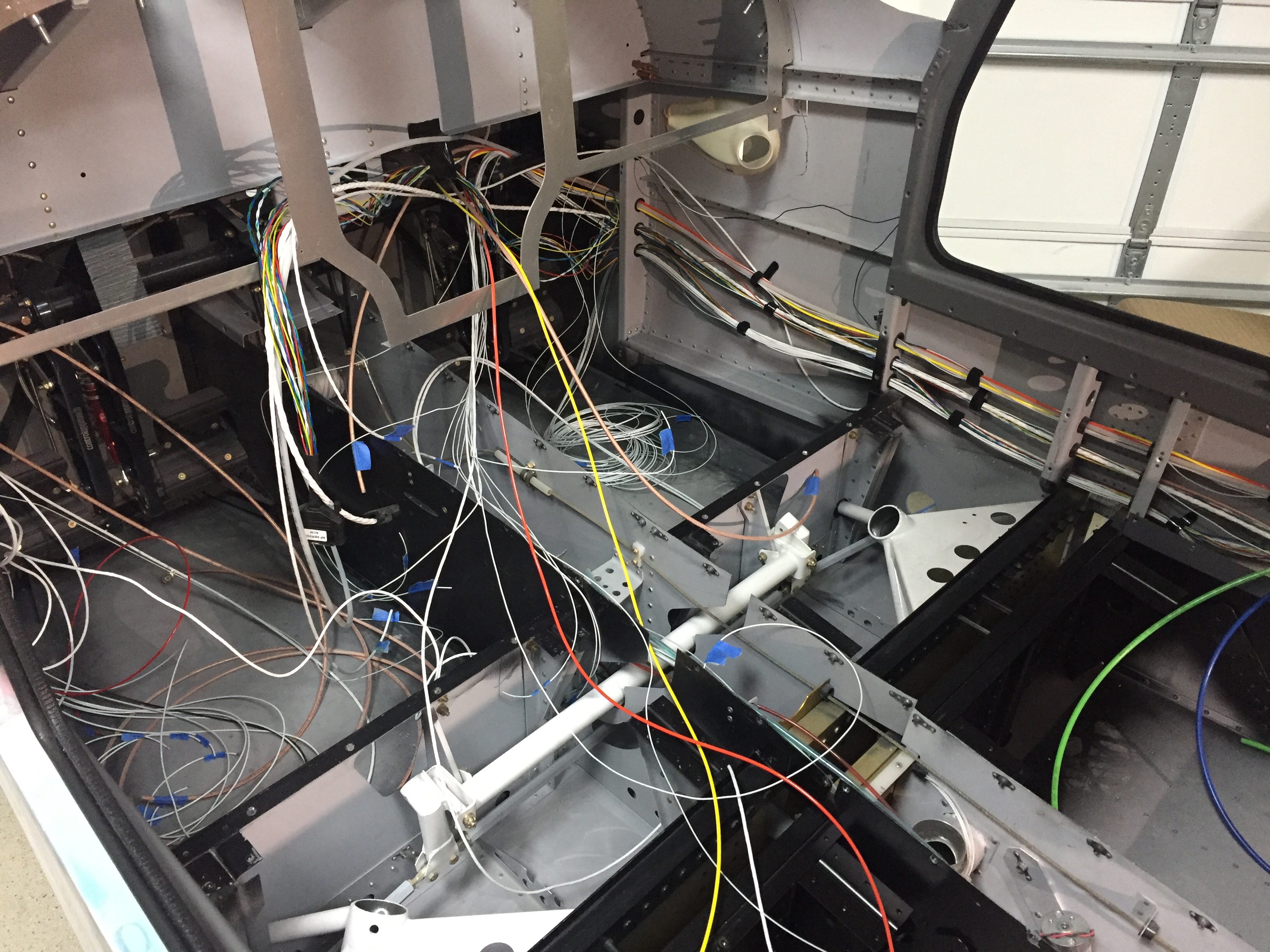
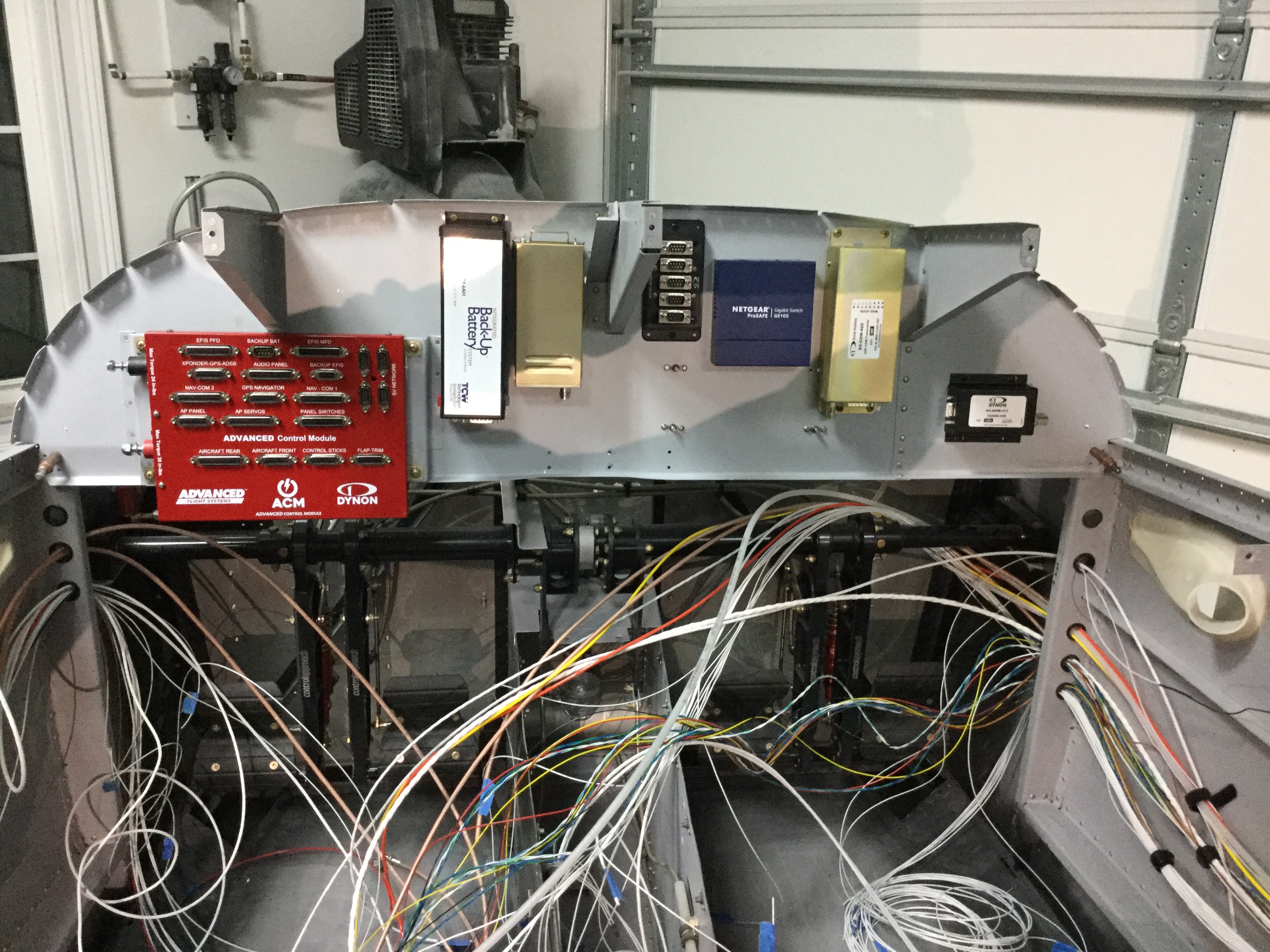
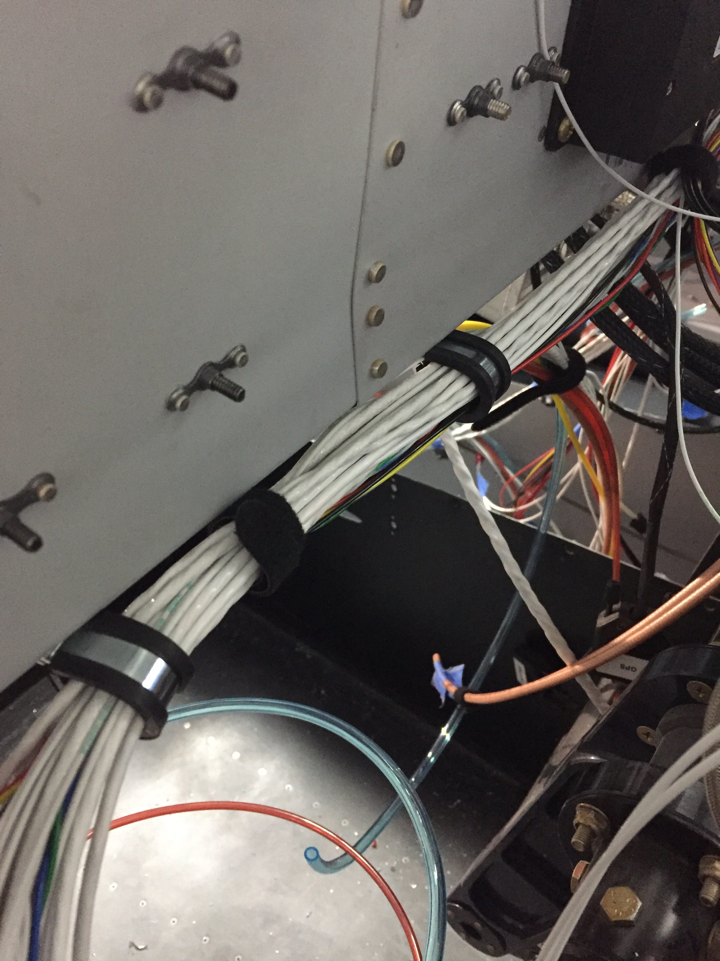
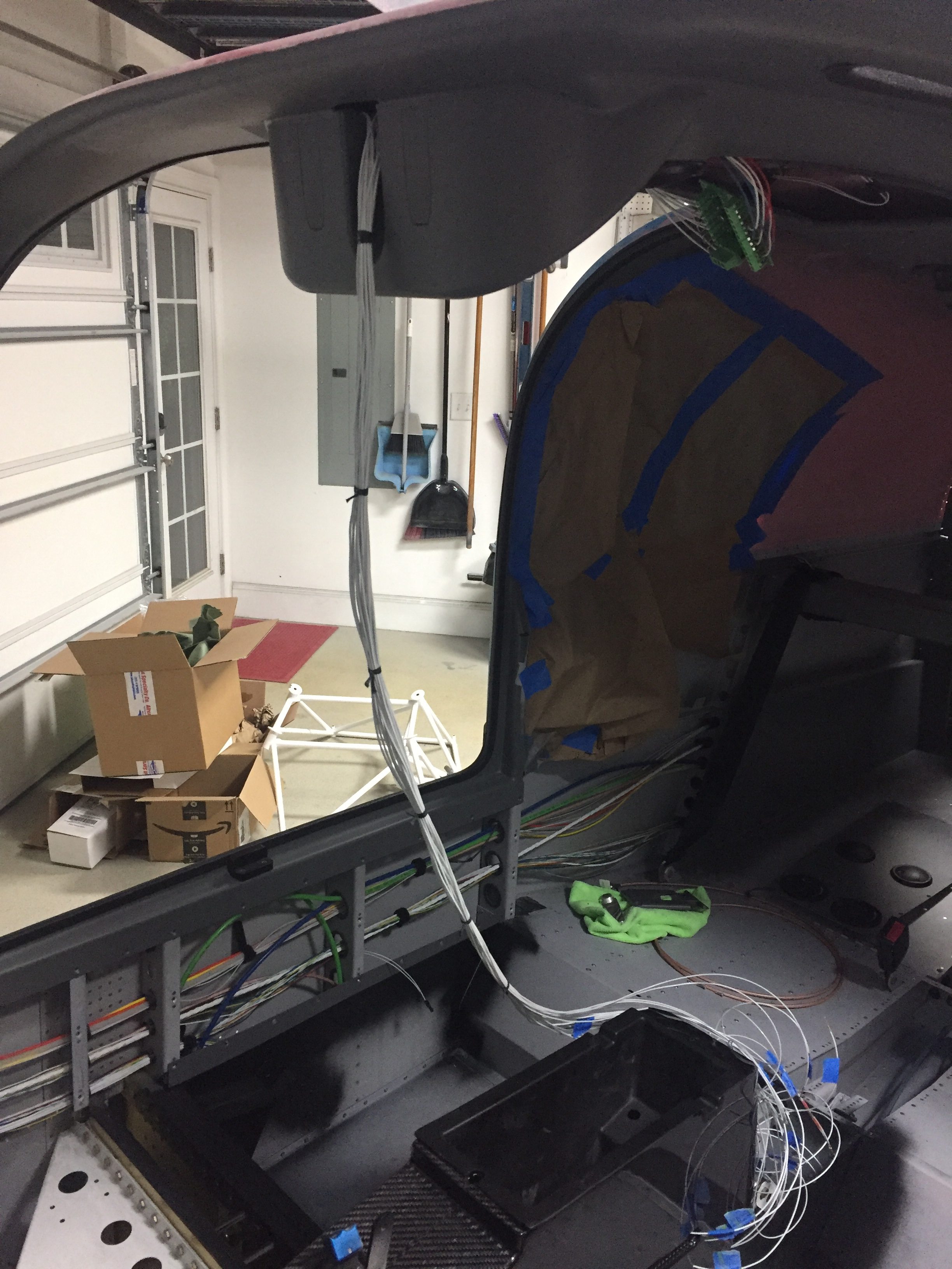
Throughout all of my work on this, I’m attempting to stay neat and organized. At least in the plane, if not the shop and workbenches. I got some cheap Velcro wire wraps from Amazon to help bundle wires as I went. It also helped me created bundles and locate clamps that will need to be installed. I’m running the majority of wire together along the bottom flange of the subpanel. Some folks try to separate a lot of different things depending on current/signal/etc. but I’ve seen a lot of professionals put everything in one giant bundle including some big names in the avionics world. I did keep the coax in its own bundle as much as possible and am trying to keep the thick wire away from other smaller wires.

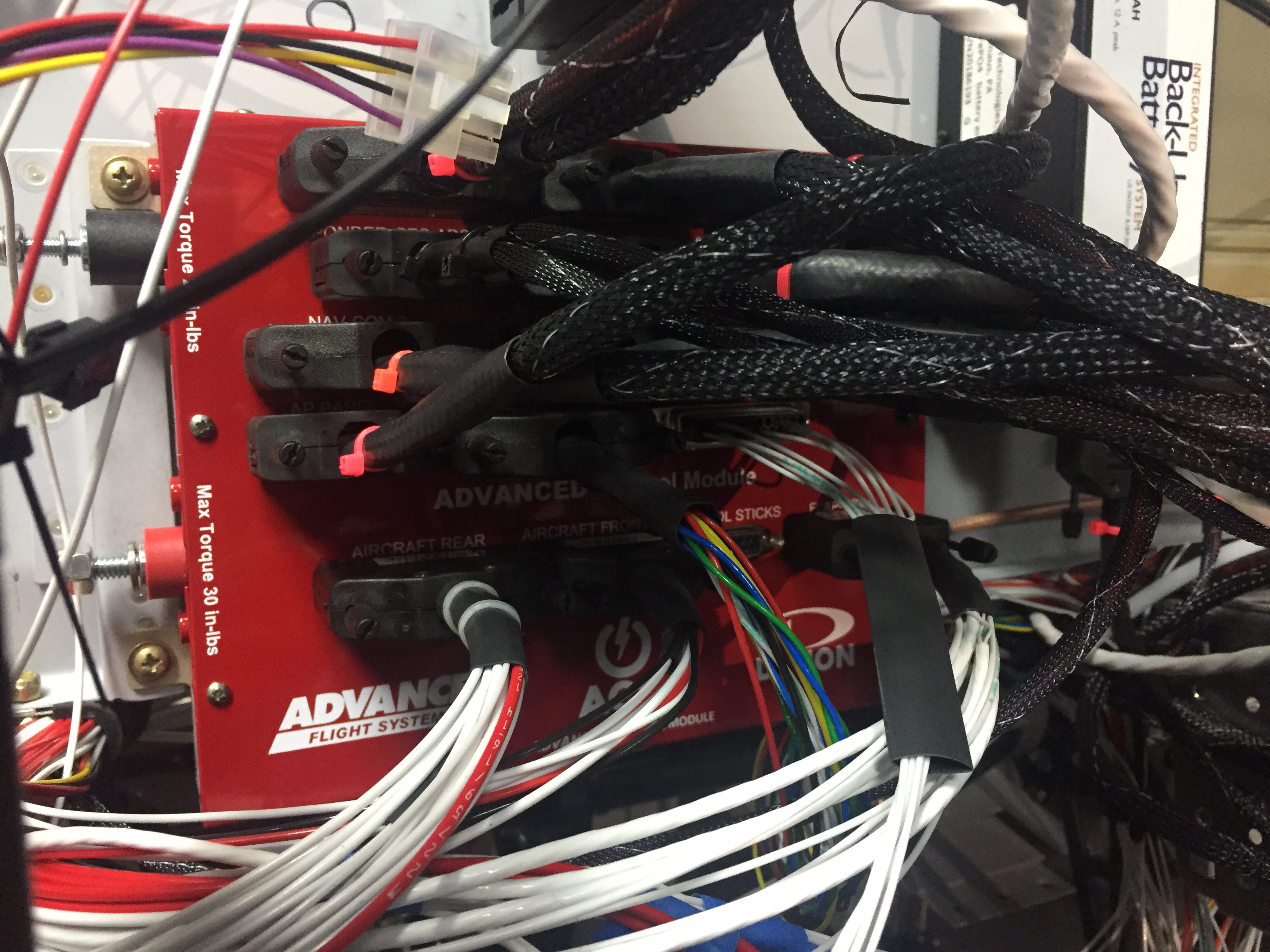
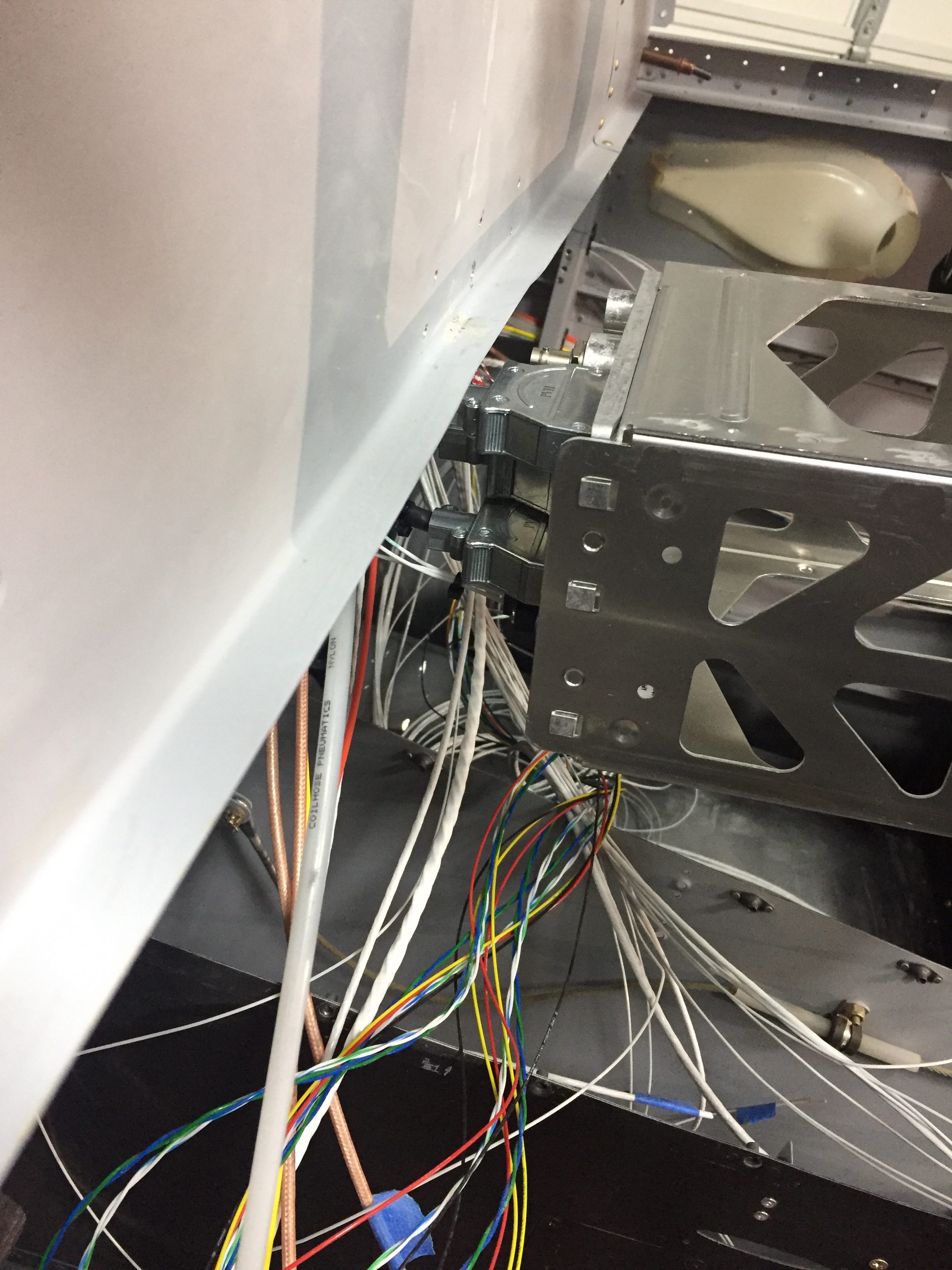
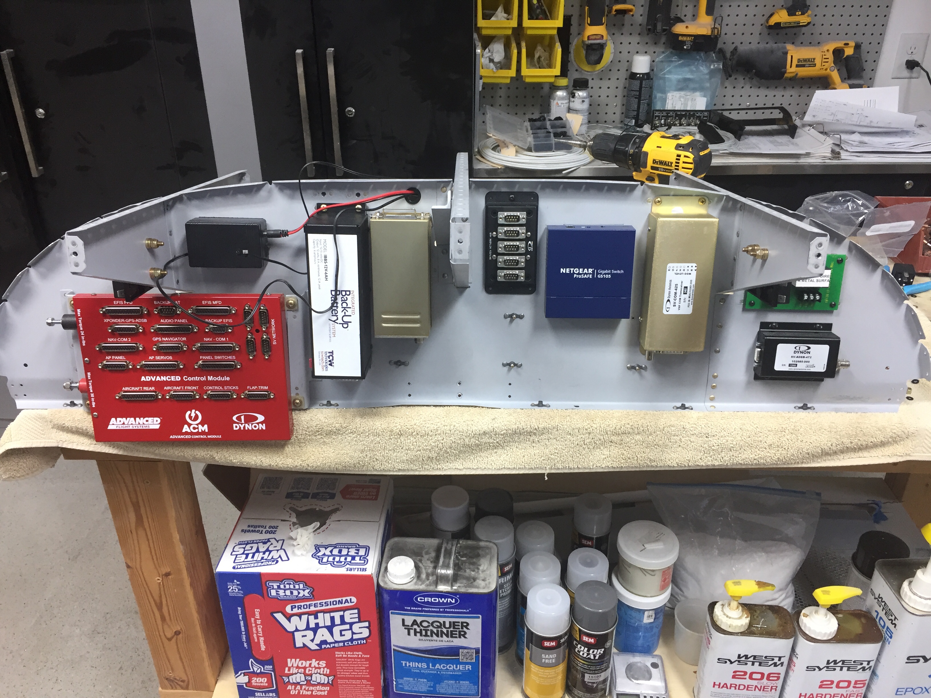
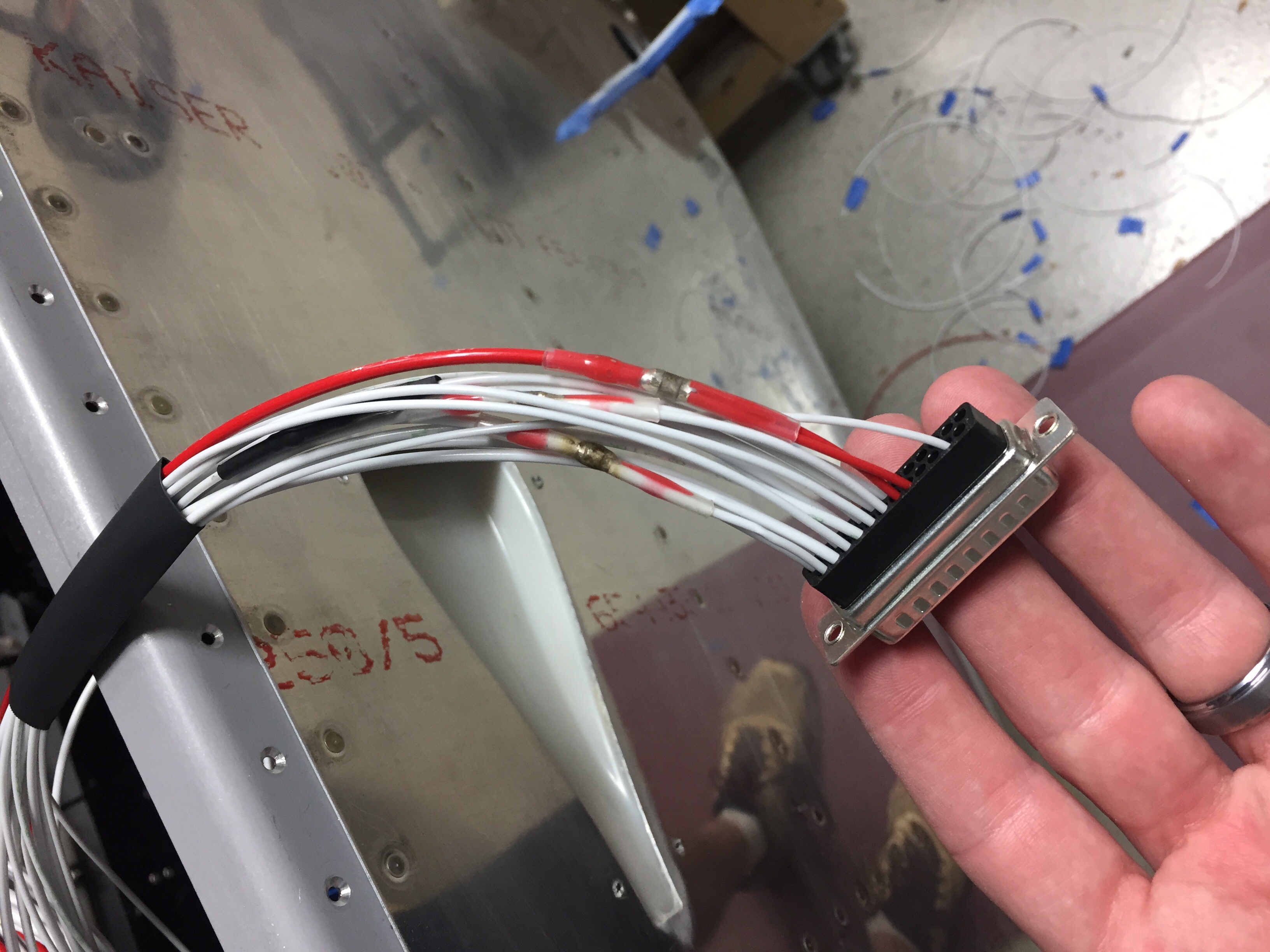
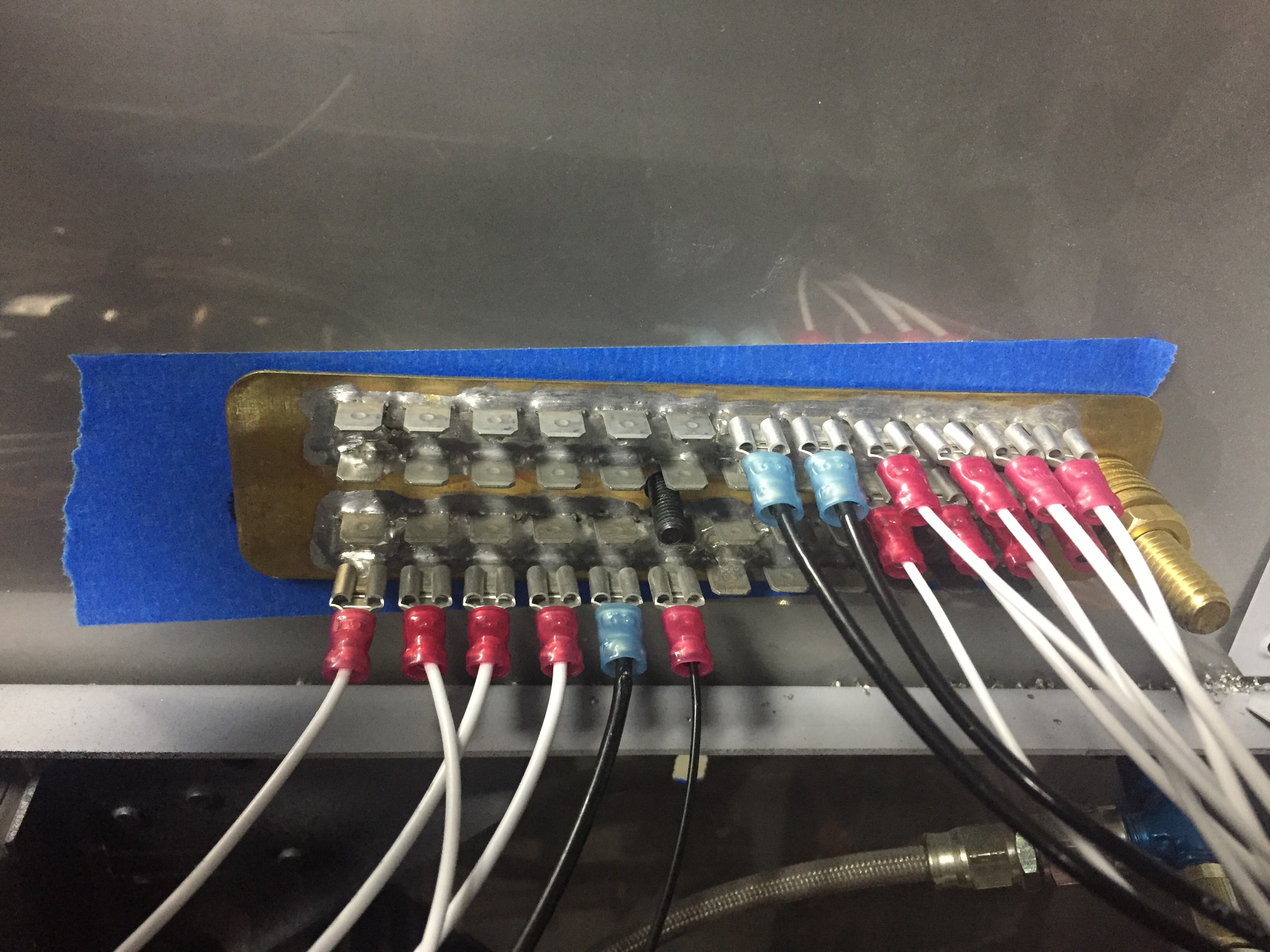
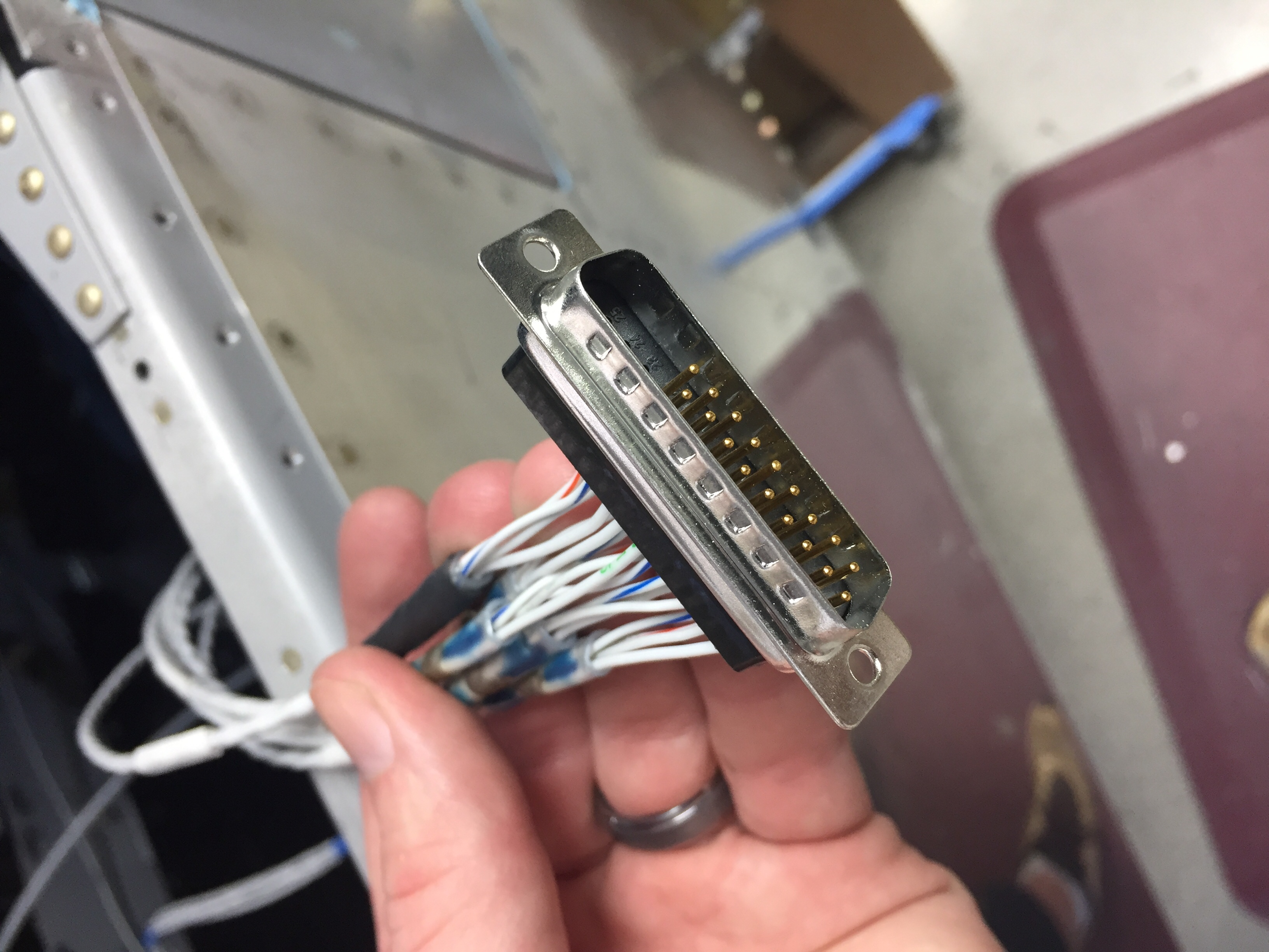
I first terminated the wires going to the ACM with pins according to the ACM pin out diagram. I had to make a few customizations such as two pins per device for high amperage draws like the landing lights. The ACM only supports 5 amps per pin, so you use two pins and a pigtail on the main wire. This is where solder sleeves really come in handy and have proven more than their weight in gold from Amazon aircraft supply. I took my time and ensured each wire was the proper connection / pin assignment as I went along. Before you knew it, I was done with a 25 pin DSub. I sort of wish I had used DSubs everywhere as they are just so easy to pin. I completed the connectors on the ACM sans the switch panel, as I can’t wire the overhead until the support bar is in.
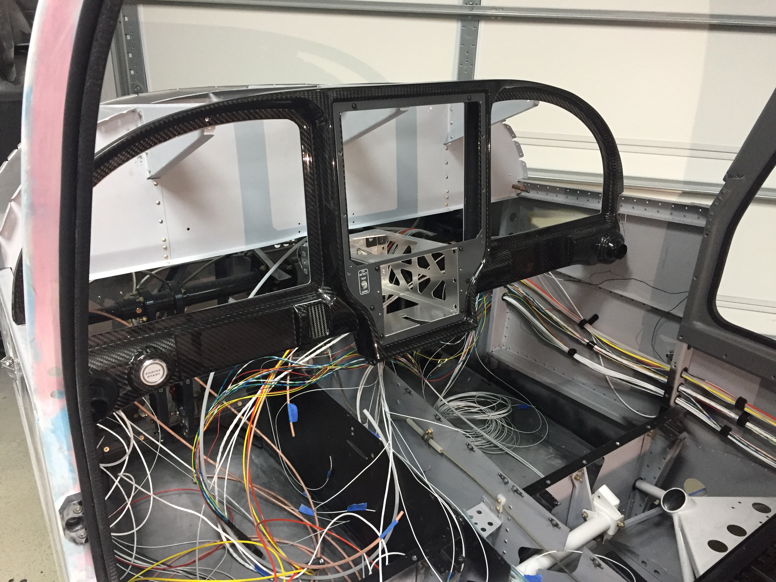
I also got most of the switches wired up on the main switch panel. Since some of these switches don’t go to the ACM, I had to really map out where the wires ran and were going to be bundled. I also had to get a bit creative on my configuration of the DPDT switches since I wanted off on the bottom and normal flight status on the top of the toggle throw. This is picky, but I like everything needed to be operating in the up position and everything off in the down position as a quick way to cross check status of systems. I have been and continue to use simple painters tape labels for the wires. This will surely cause shock and awe on some builders who insist on heat shrink or diamond laser etching of each wire, but it’s working great for me and is quick and easy. Once I pin the wire and connect it, I remove the label as long as it’s verified on my wiring schematic that’s a work in progress now that I’m actually wiring.
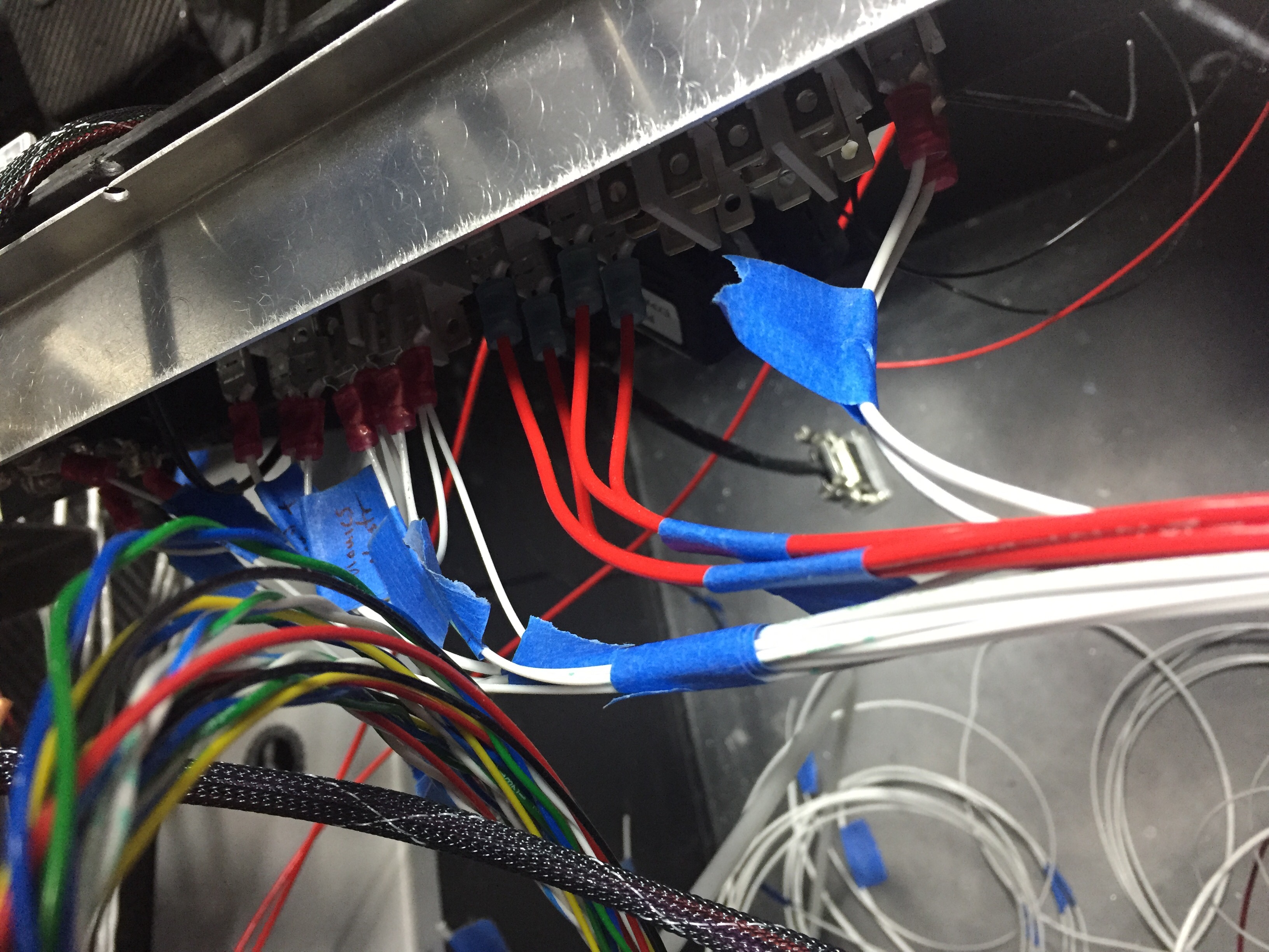
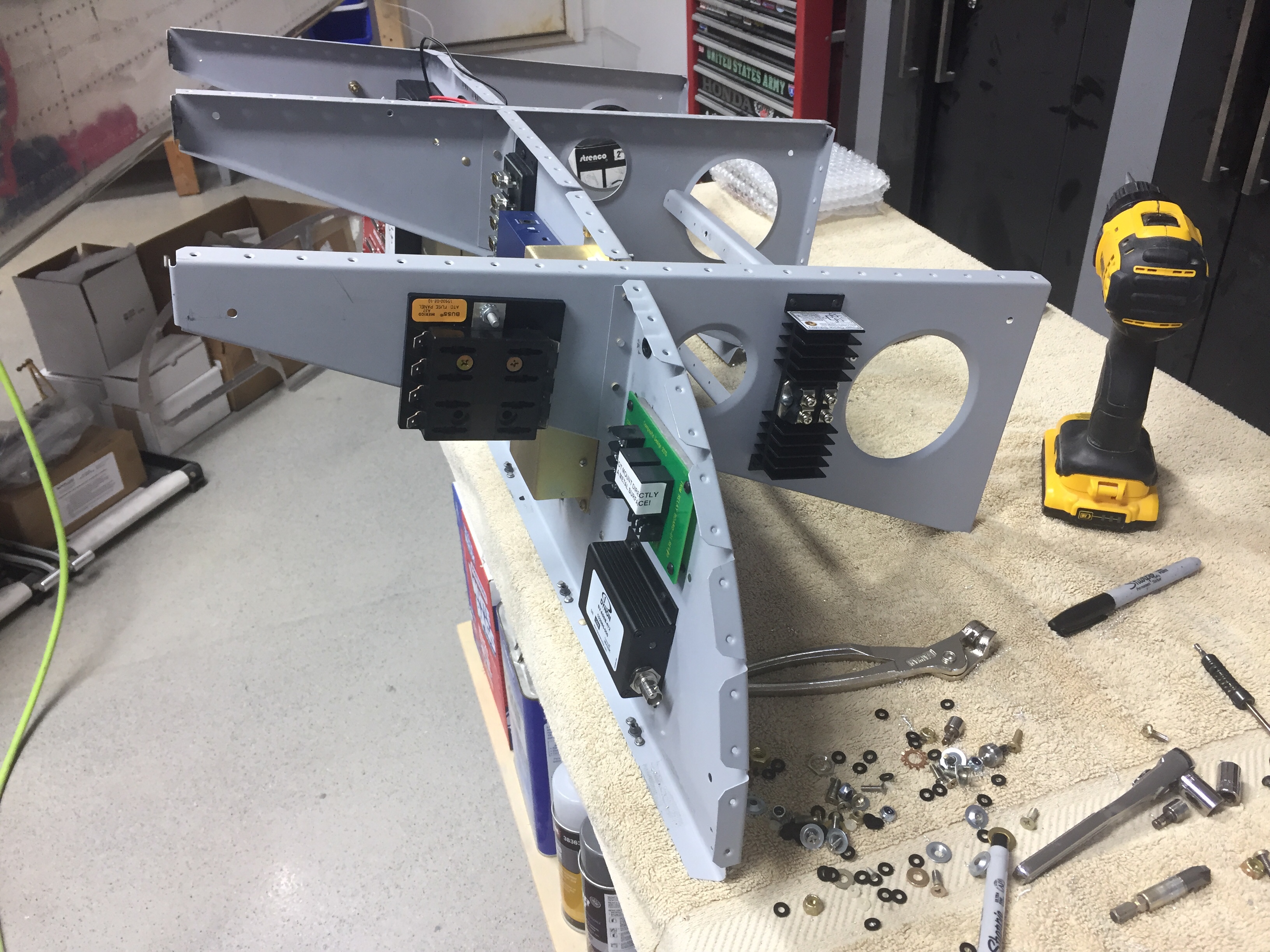
I will go back and do a permanent label on wires leading to the switch terminals just to make it easier down the road to R2 a switch. On the grounding forest of tabs, I have a chart created that identifies each tab A-D, 1-12. So down the road if I need to trace a ground or change something, I can refer to the diagram and see the assignment of B4 going to the taxi light, for example. I still have some grounds to add, but I don’t have nearly as many as I expected. I am thankful I went with the large forest, just to have the room available.
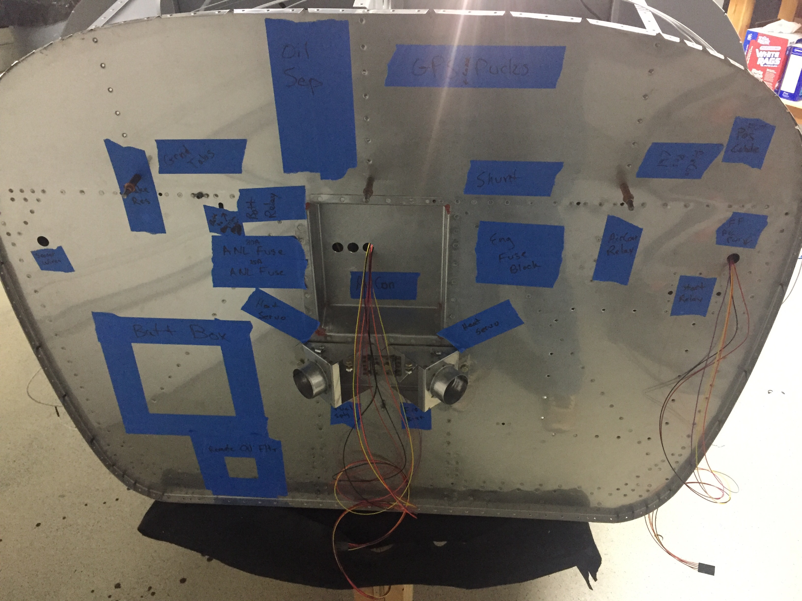
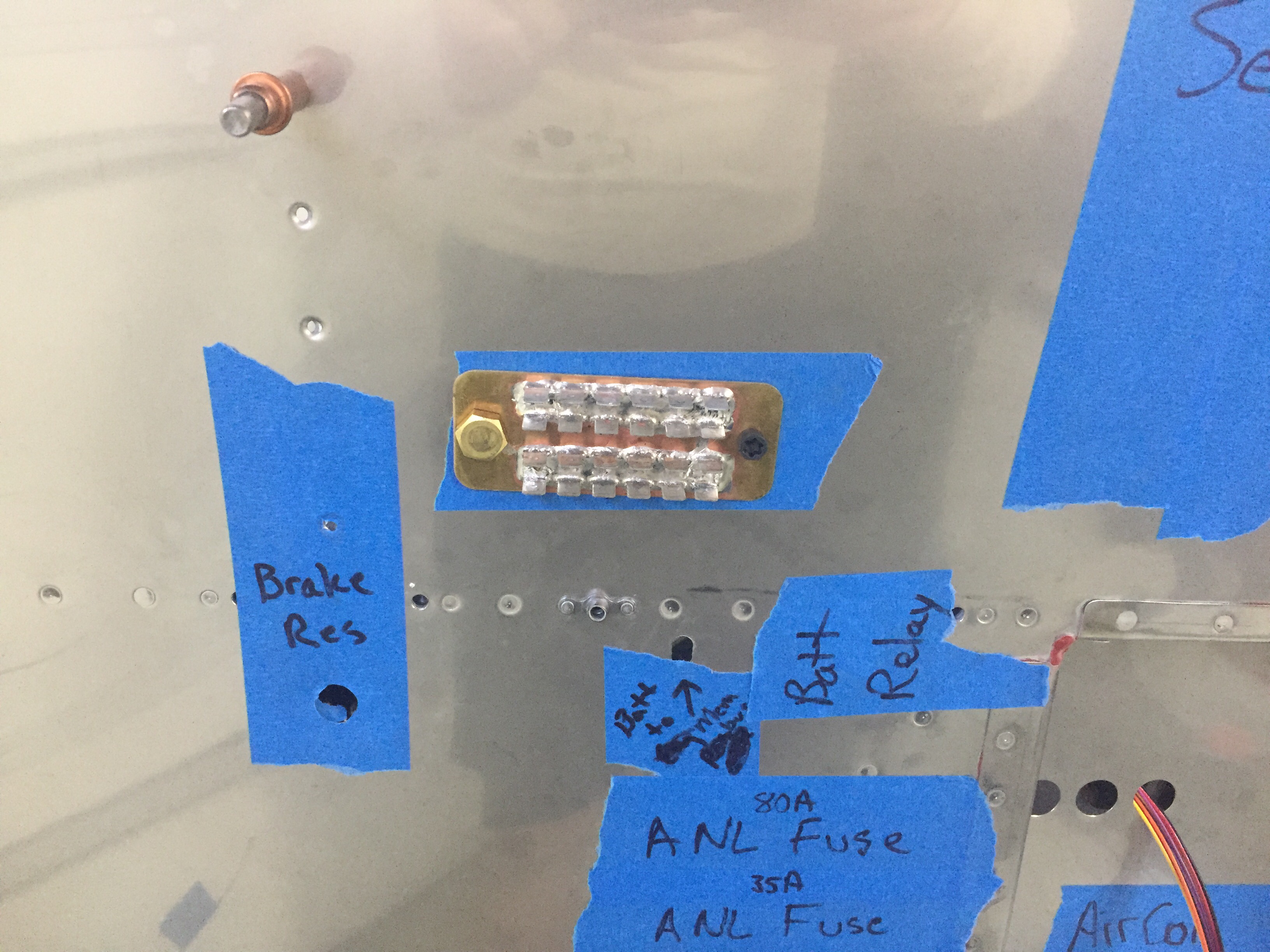
Ahh, but where to put that forest of tabs on the firewall? Where to put anything on the firewall? Well, after a few hours of staring at the stainless steel canvas and talking to myself at length, I embarked on an art project of painters tape and Sharpie markers. I will admittedly have a lot of stuff mounted to my firewall. I’m doing that to avoid extra weight in the back of the plane (since the aircon and O2 is back there) and to keep wire runs short. Having two alternators, a ground power receptacle, and a few other items, the list of things is pretty long. It’s a bit of a puzzle to figure out where everything needs to go, especially not having the engine yet. Fingers crossed that staring at pictures and asking for a ton of measurements from other builders will prove sufficient in placing. I held my breath and drilled the first hole for the grounding tabs.
Back on the inside, I laced all of the wires going to the cabin overhead in preparation of running them down the support bar. The bar and now modified engine mount is at powder coating this week and should be a nice black by Friday. I will wire the remaining lighting switches and interior lighting control module once the forward fuselage section is permanently installed with the support bar and top skin.
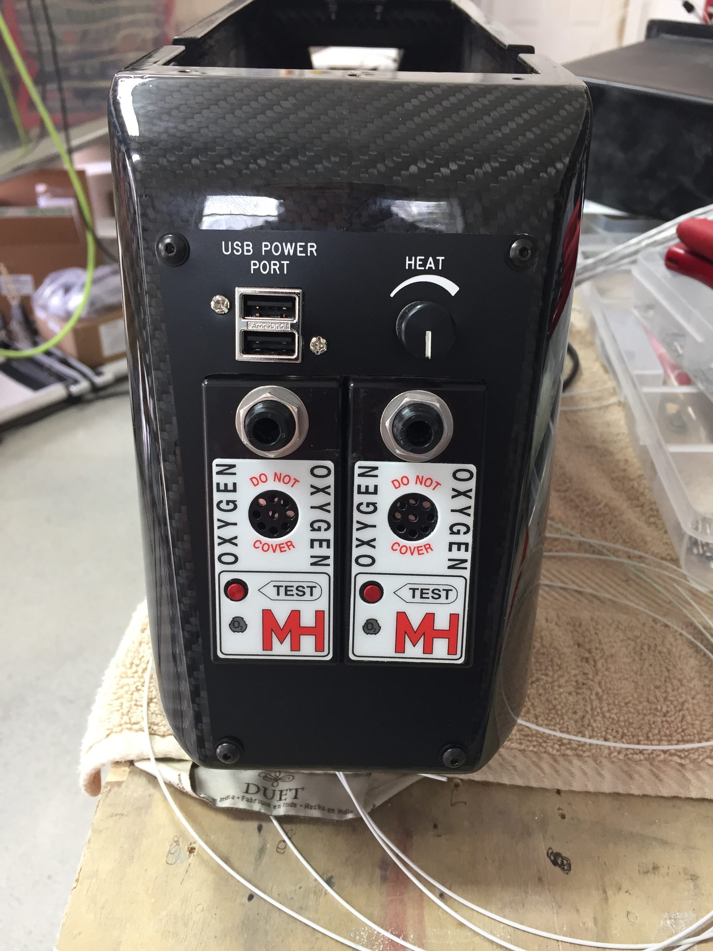
The center console wiring was buttoned up with a DSub to allow the console’s removal in the future without needing to pull all of the headset jacks out. Again the solder sleeves make easy work of pinning out the shielded wires. I also put on the rear seat panel and final installed the rear O2 ports and USB power port. It will not be back light like the front, but figure rear seat pax can turn on their task light to see if needed without affecting me as much. It came out very nicely and I’m getting excited to see the armrest cover that Aerosport is finishing up with the seats.
I finished all of the wiring I could and left it all bundled as I pulled the subpanel and premade harness out of the plane one last time. On the bench, I had to move the IBBS battery down about an inch to clear the defrost fans and installed nutplates for the clamps. Attention will now turn towards the tunnel and getting all of the associated plumbing done before putting the avionics in for good.