Let me see that glass

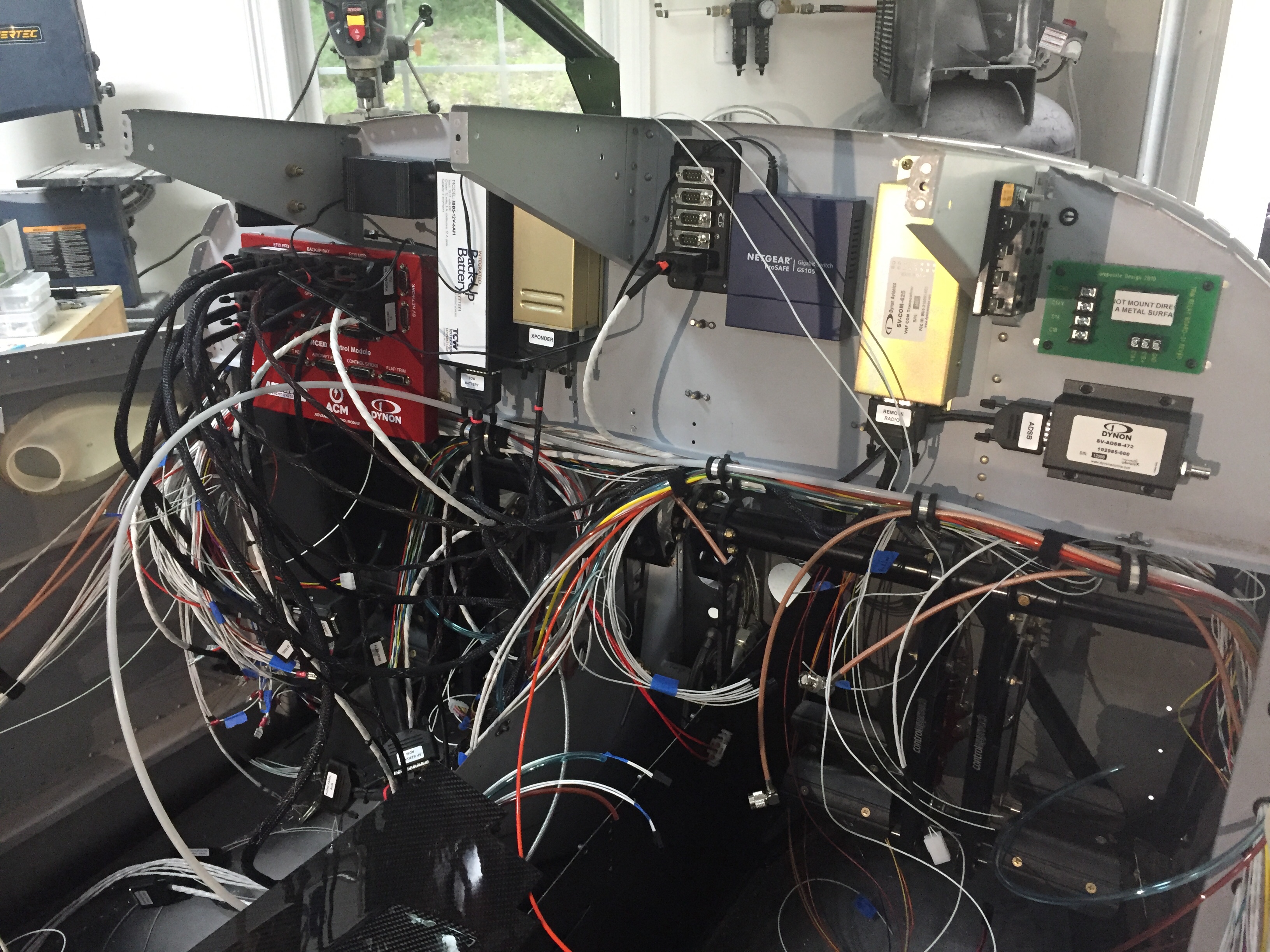
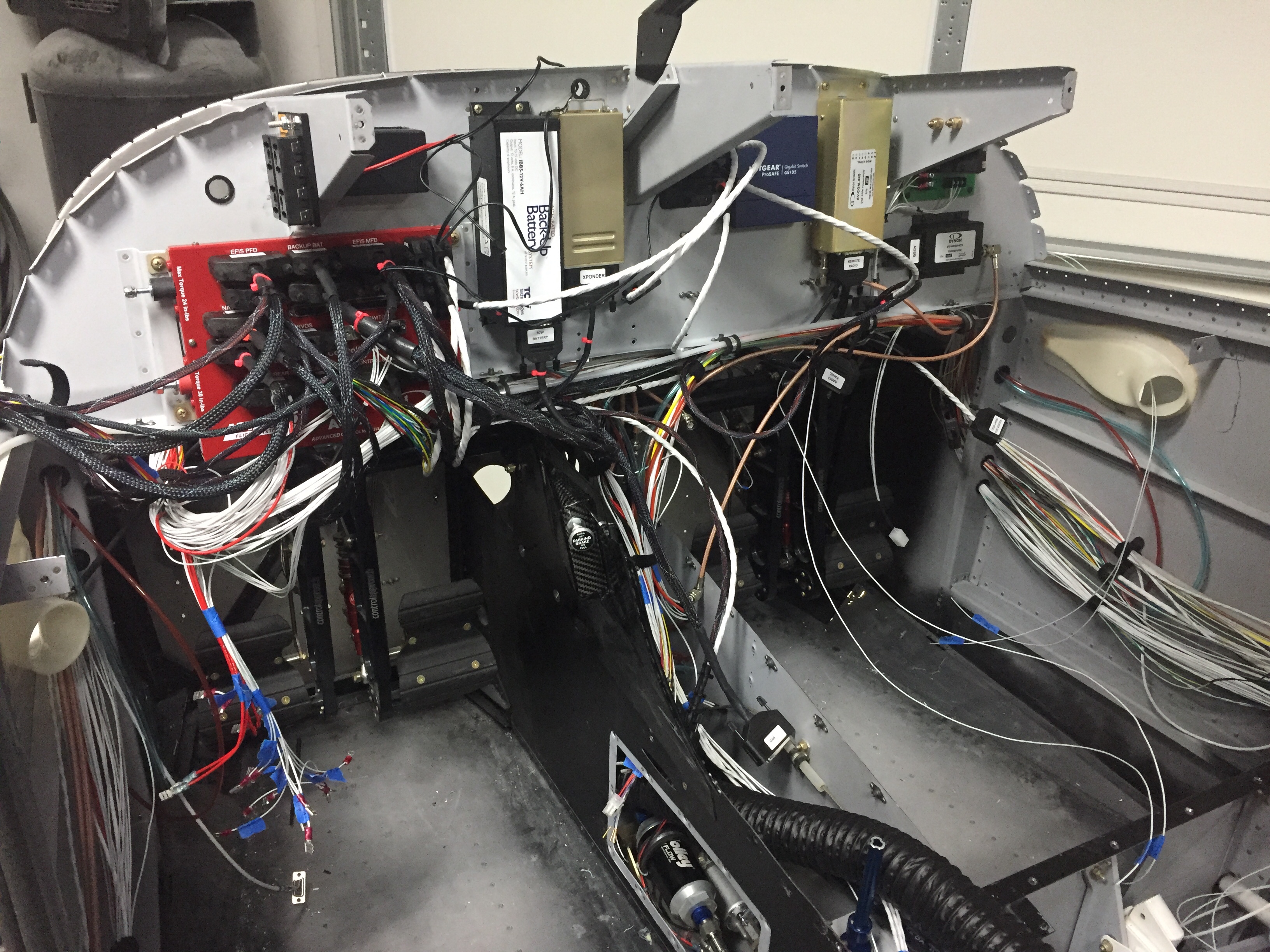
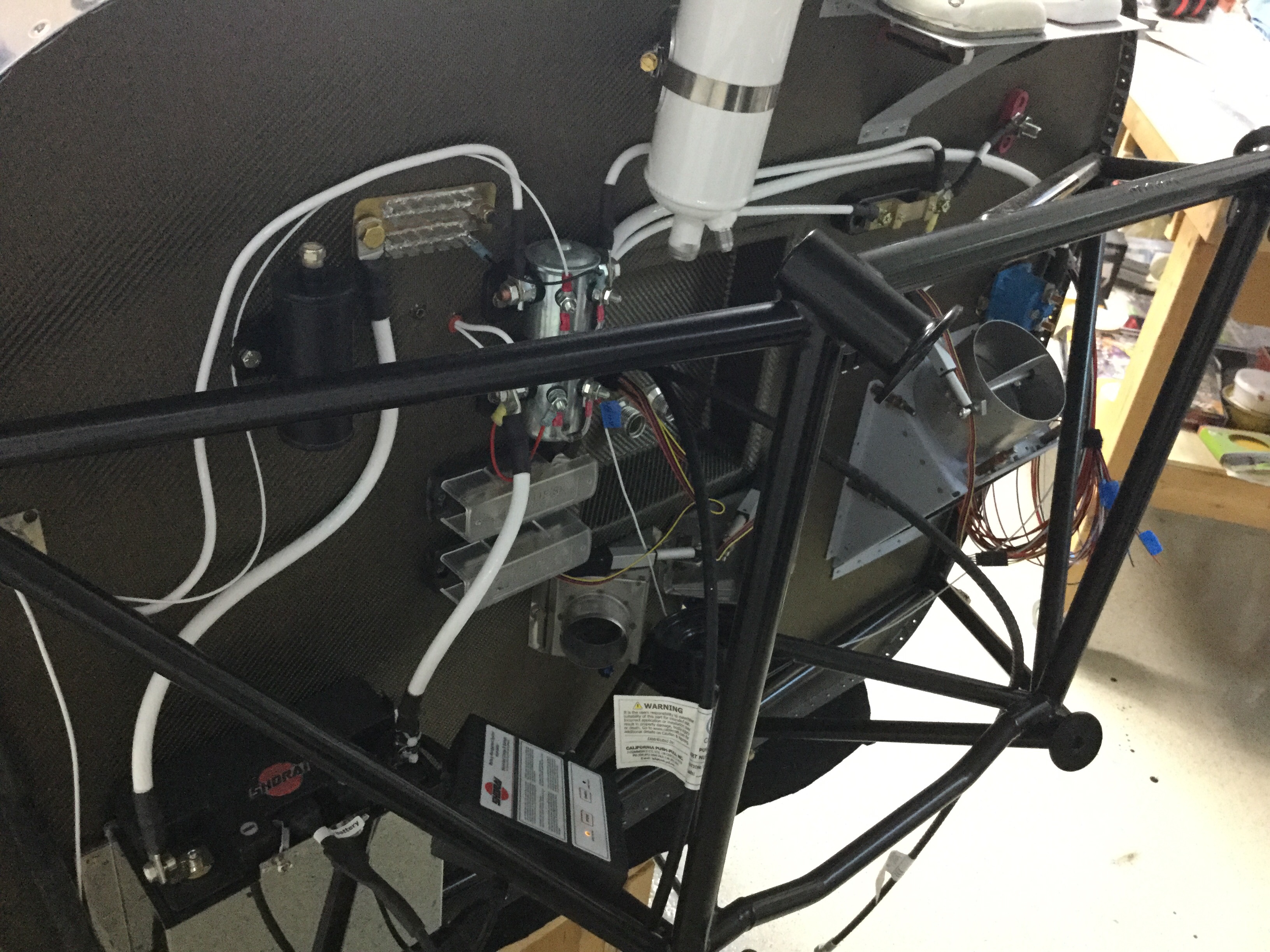
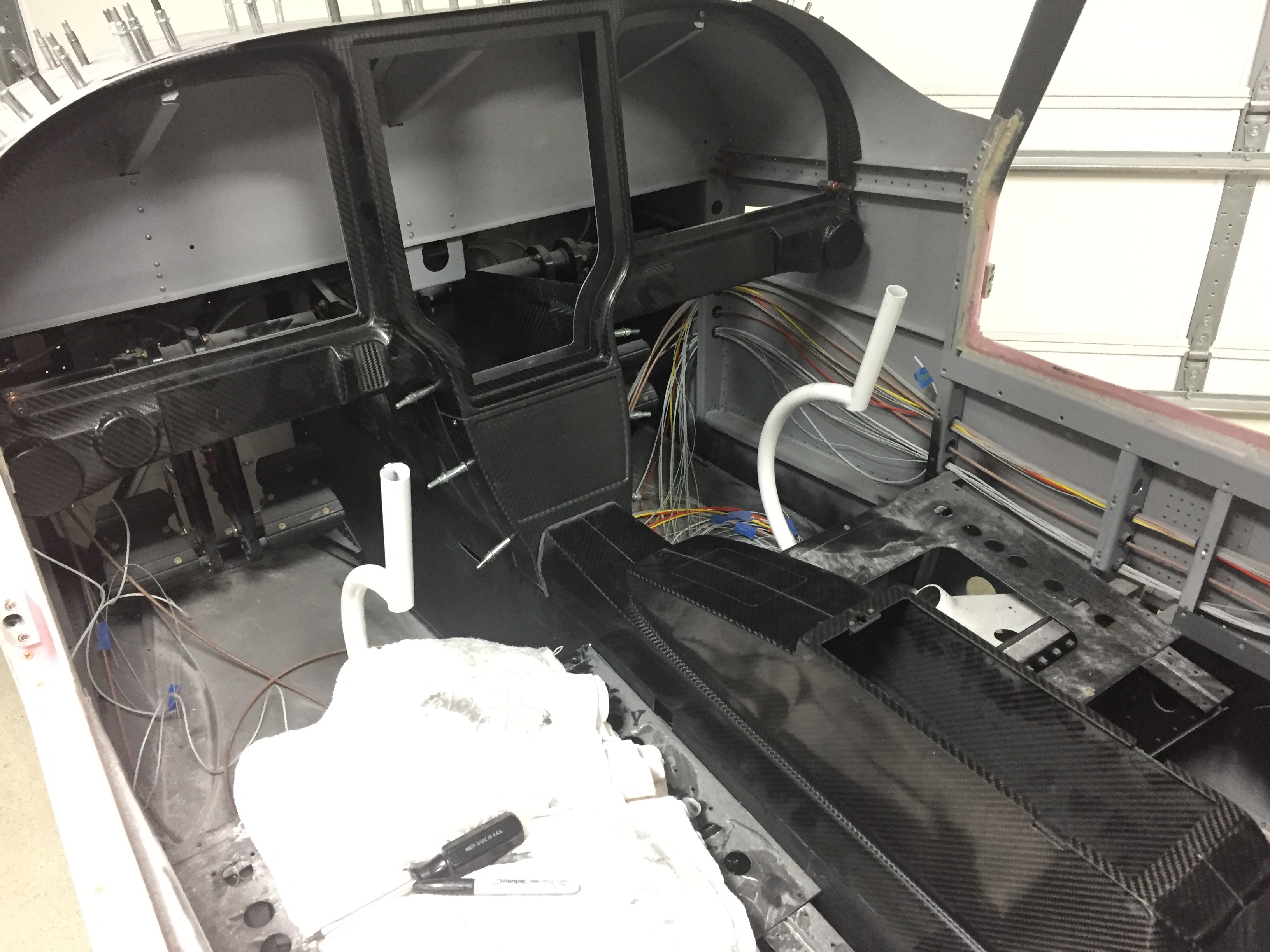
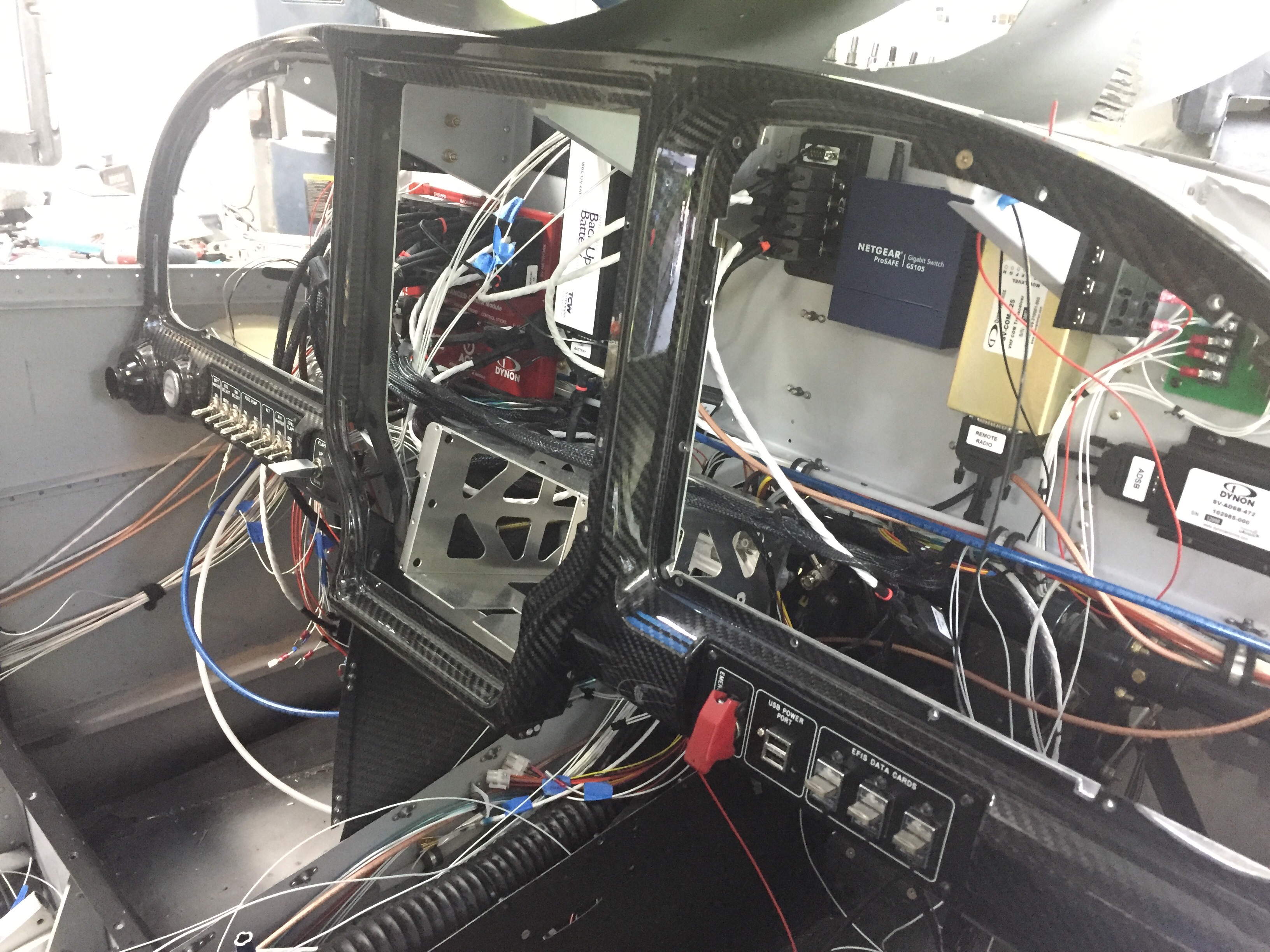
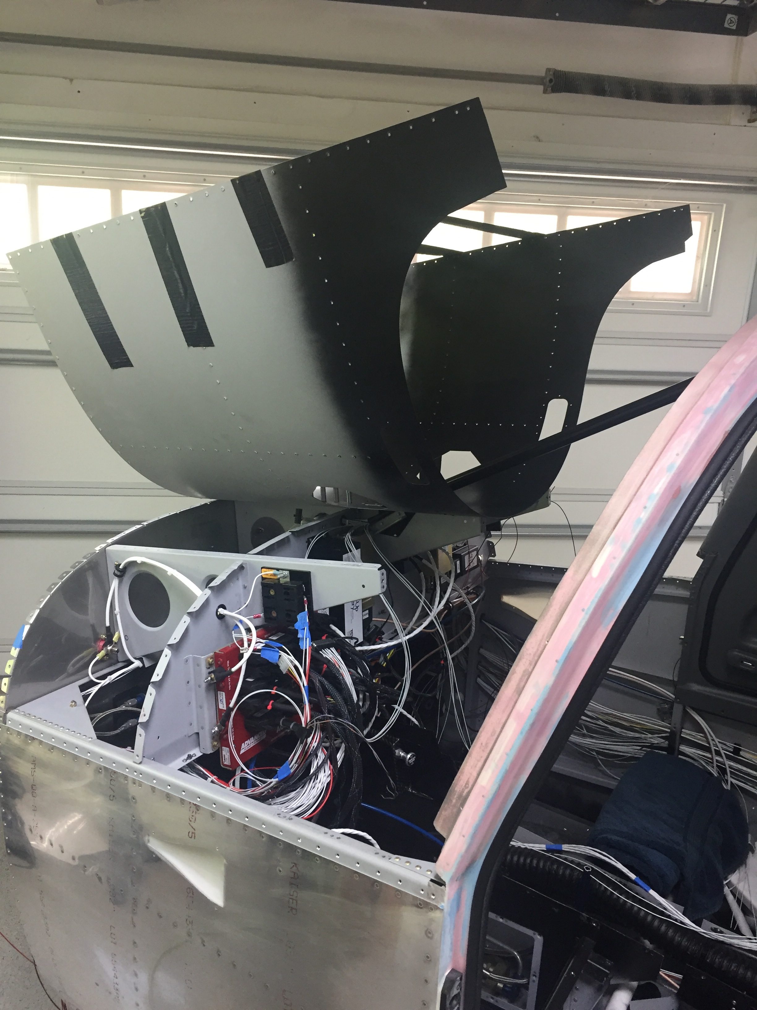
At this point, I’m out of wires to run in the plane and about out of wire from my workbench!  I made the call to rivet in the forward fuselage section structure so that the bundles could be zip-tied and I could move forward with putting the panel and avionics in for good.  (I actually riveted this in before doing the firewall insulation, but it was easier to type in this order.)  As with most big things, it was very anti-climactic and completed in about 15 minutes.

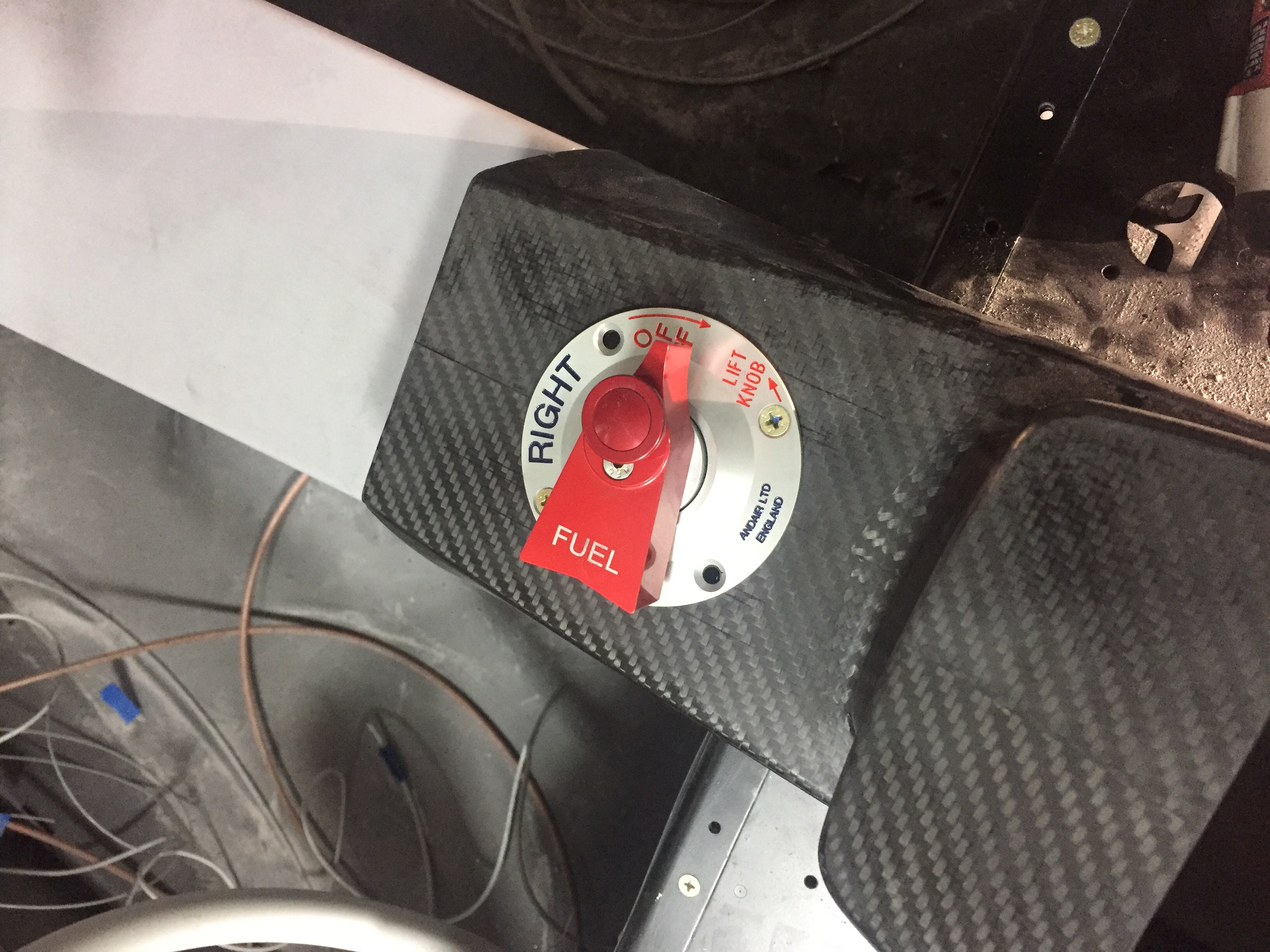
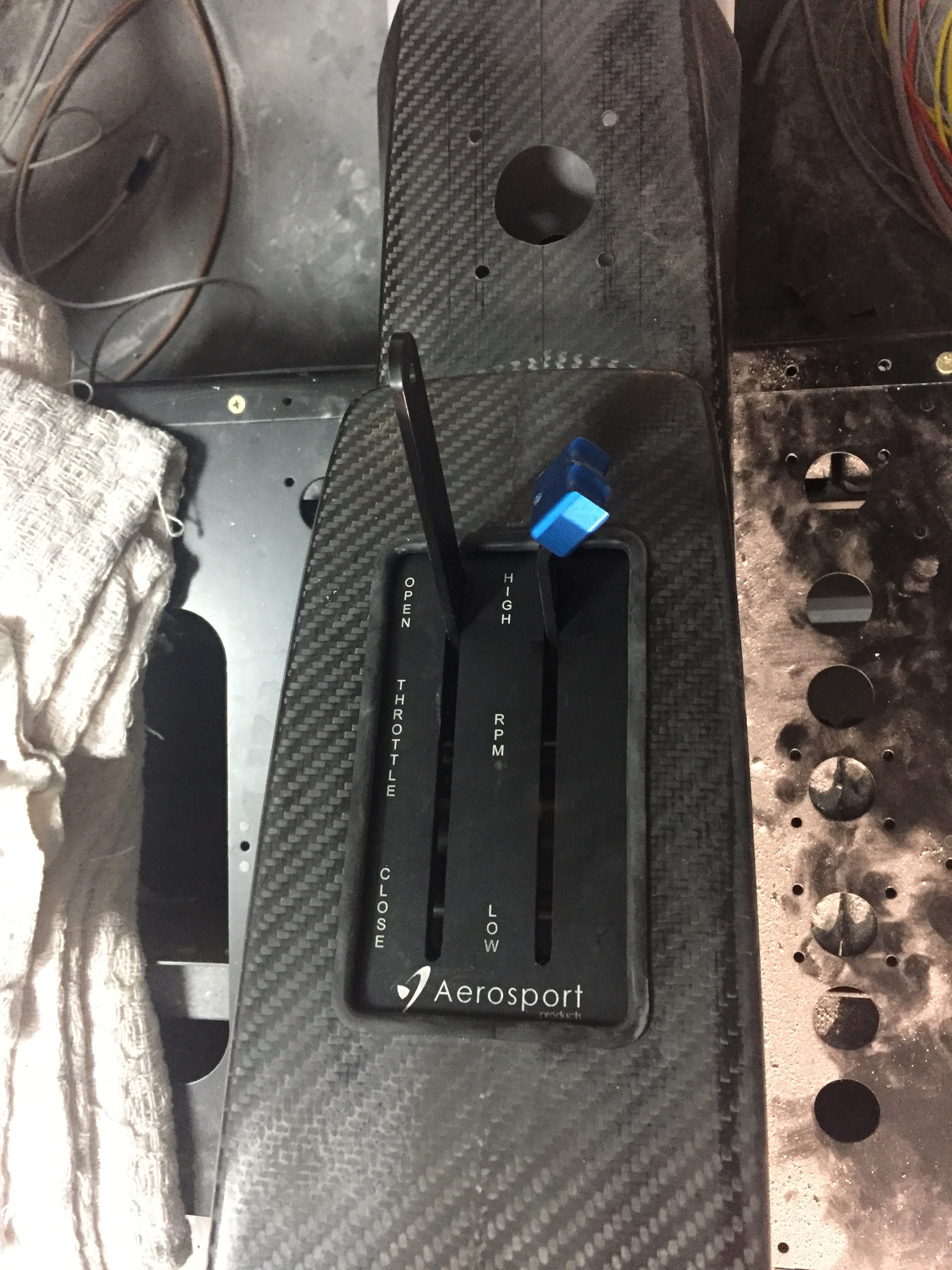
I put the carbon fiber frame and back plate in and got it all screwed together in the right order.  All of the switch panels were hooked up for good and along the way, bundles were tidied up as much as possible.

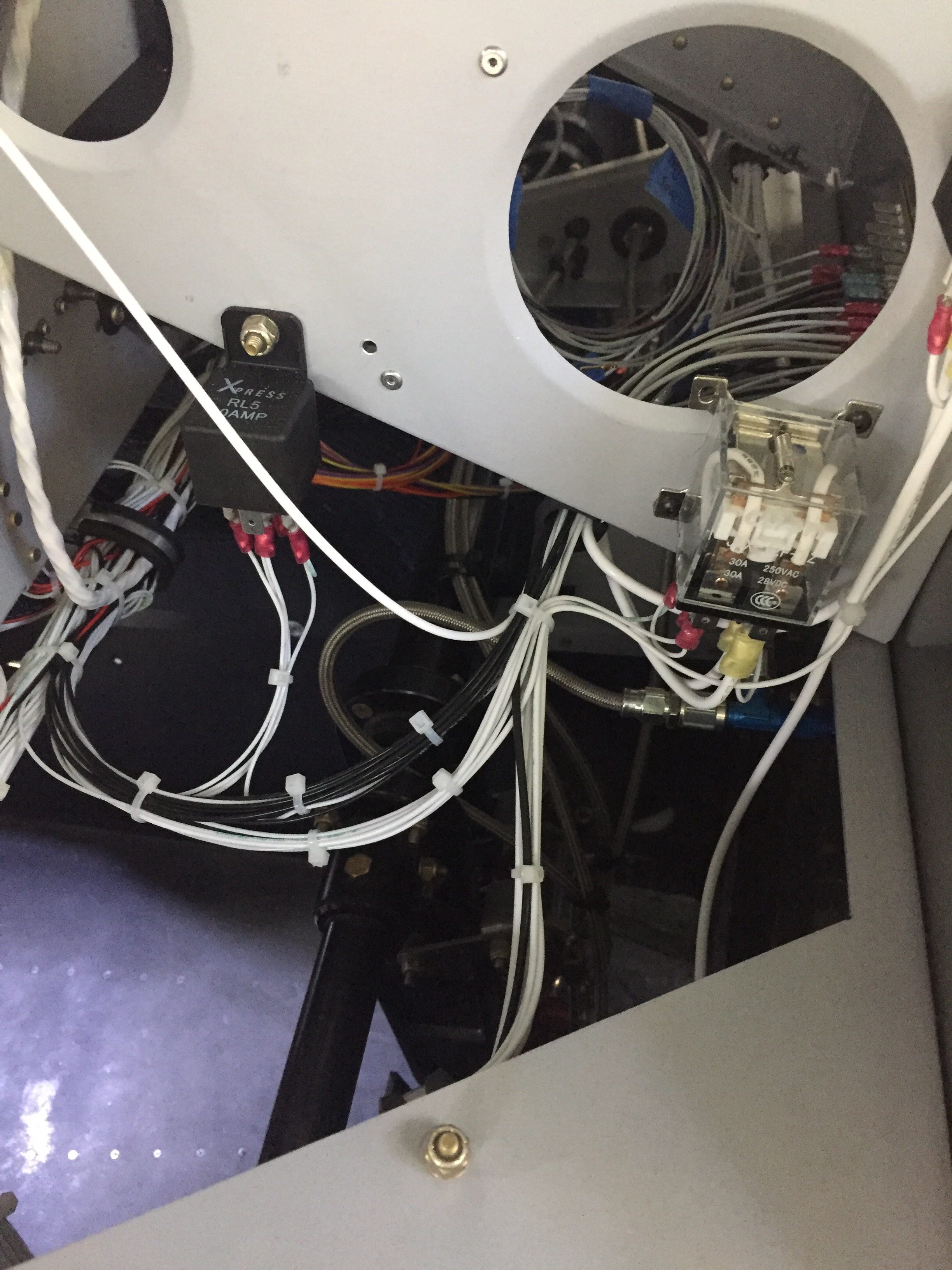
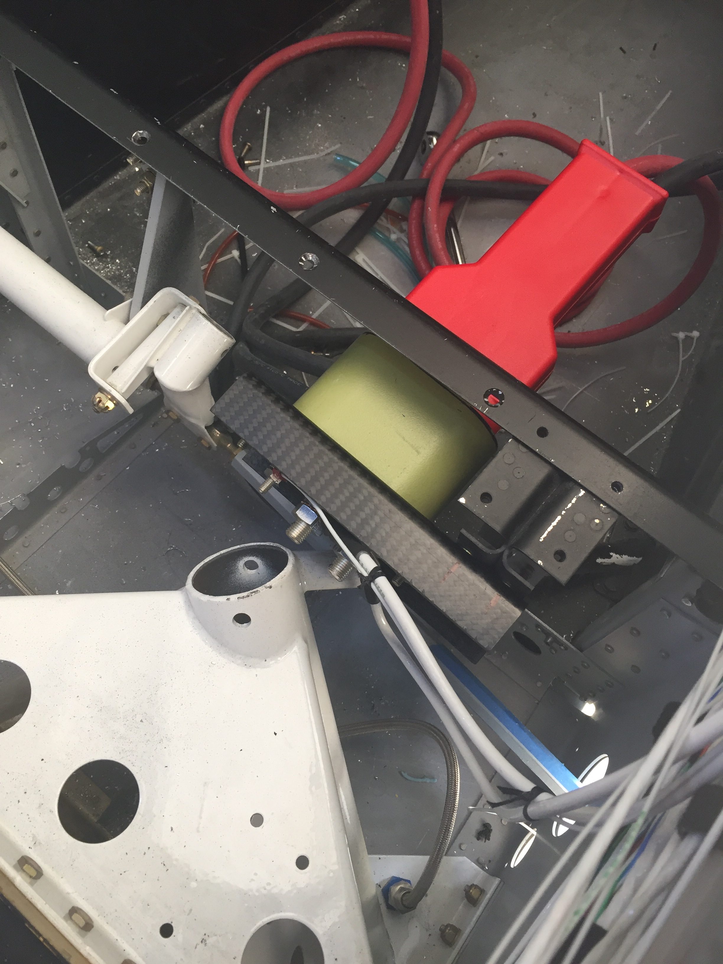
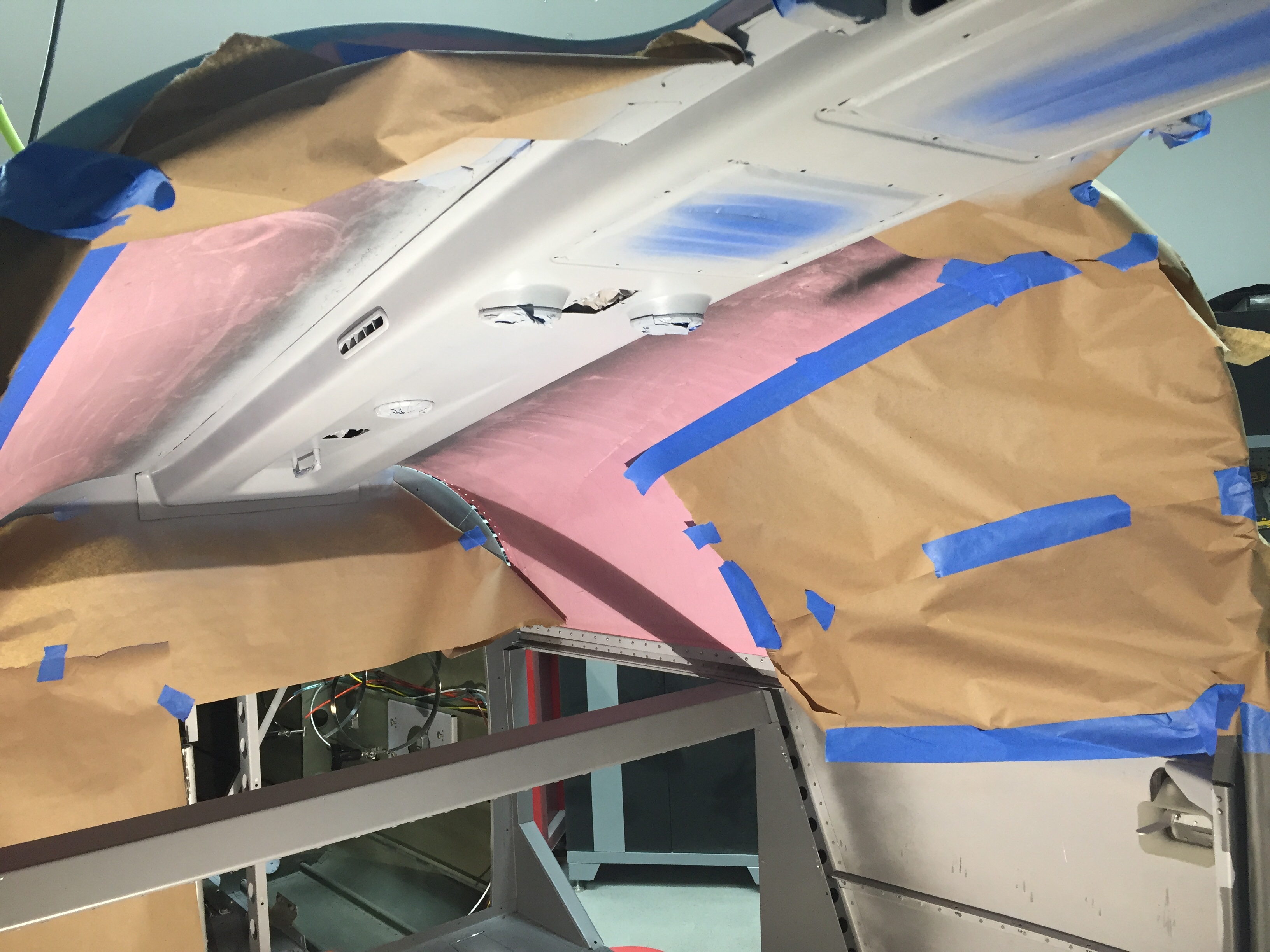
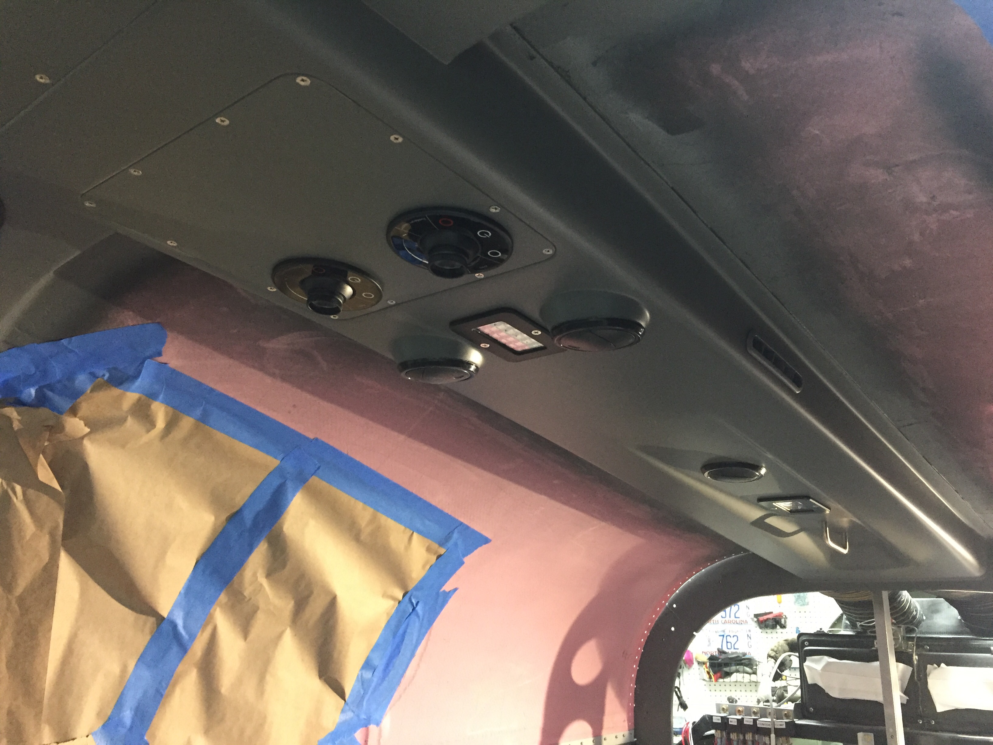
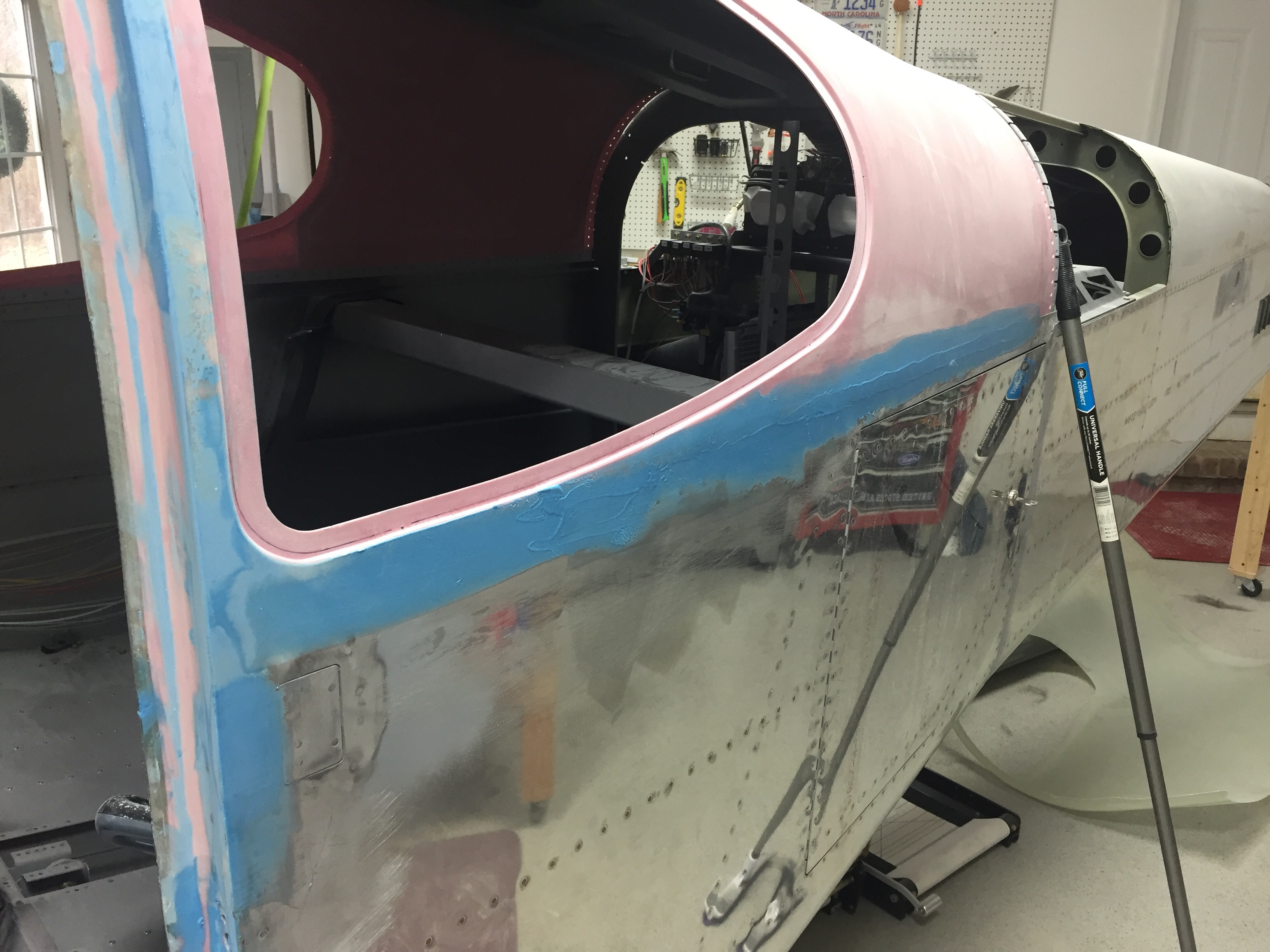
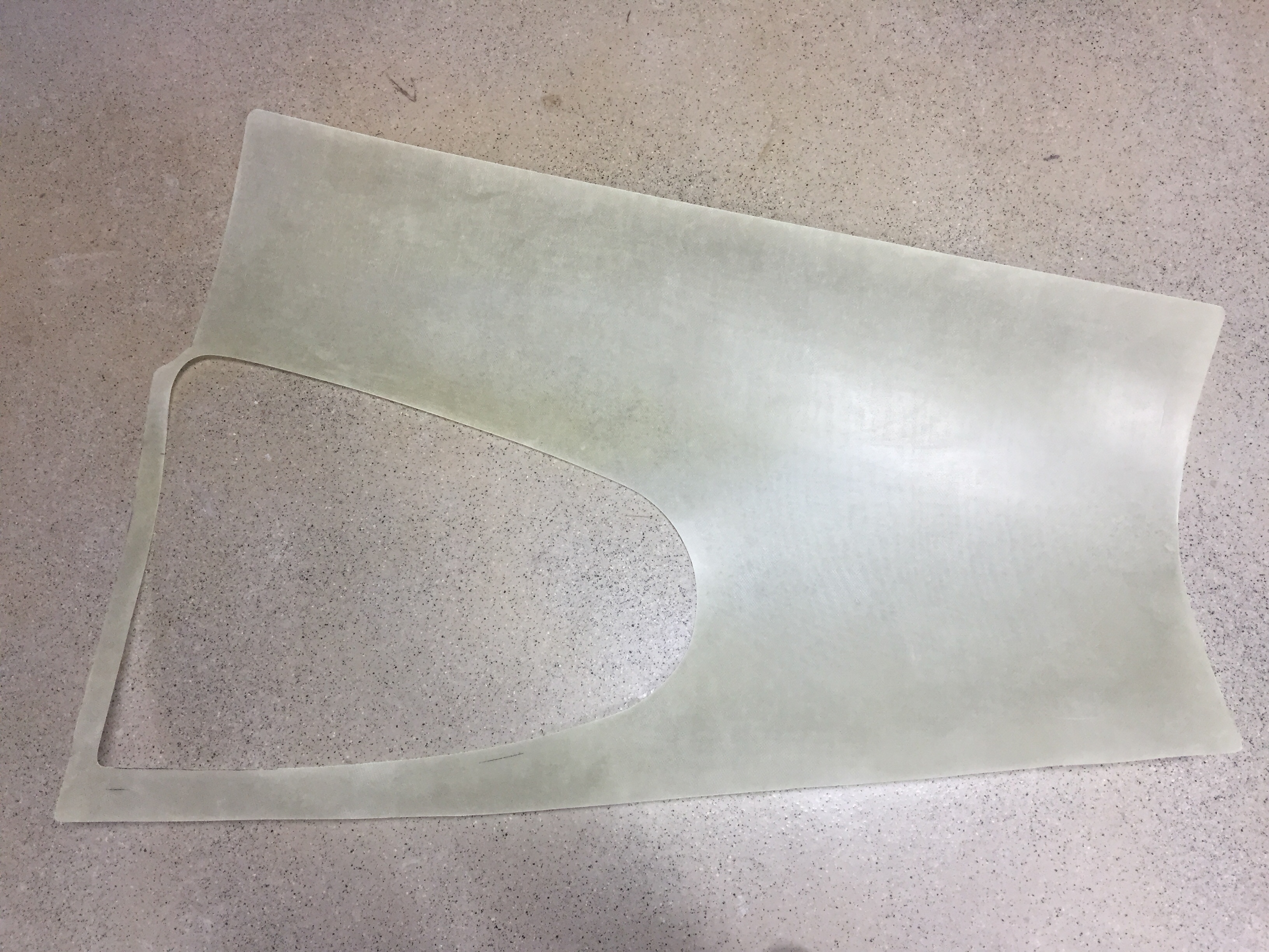
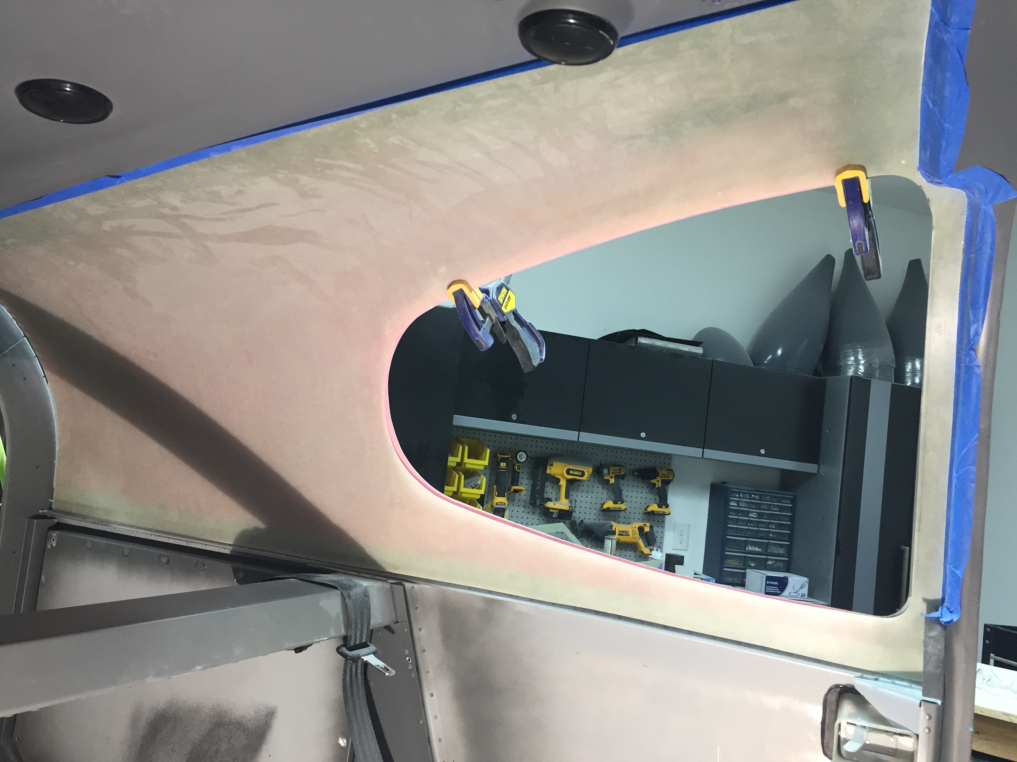
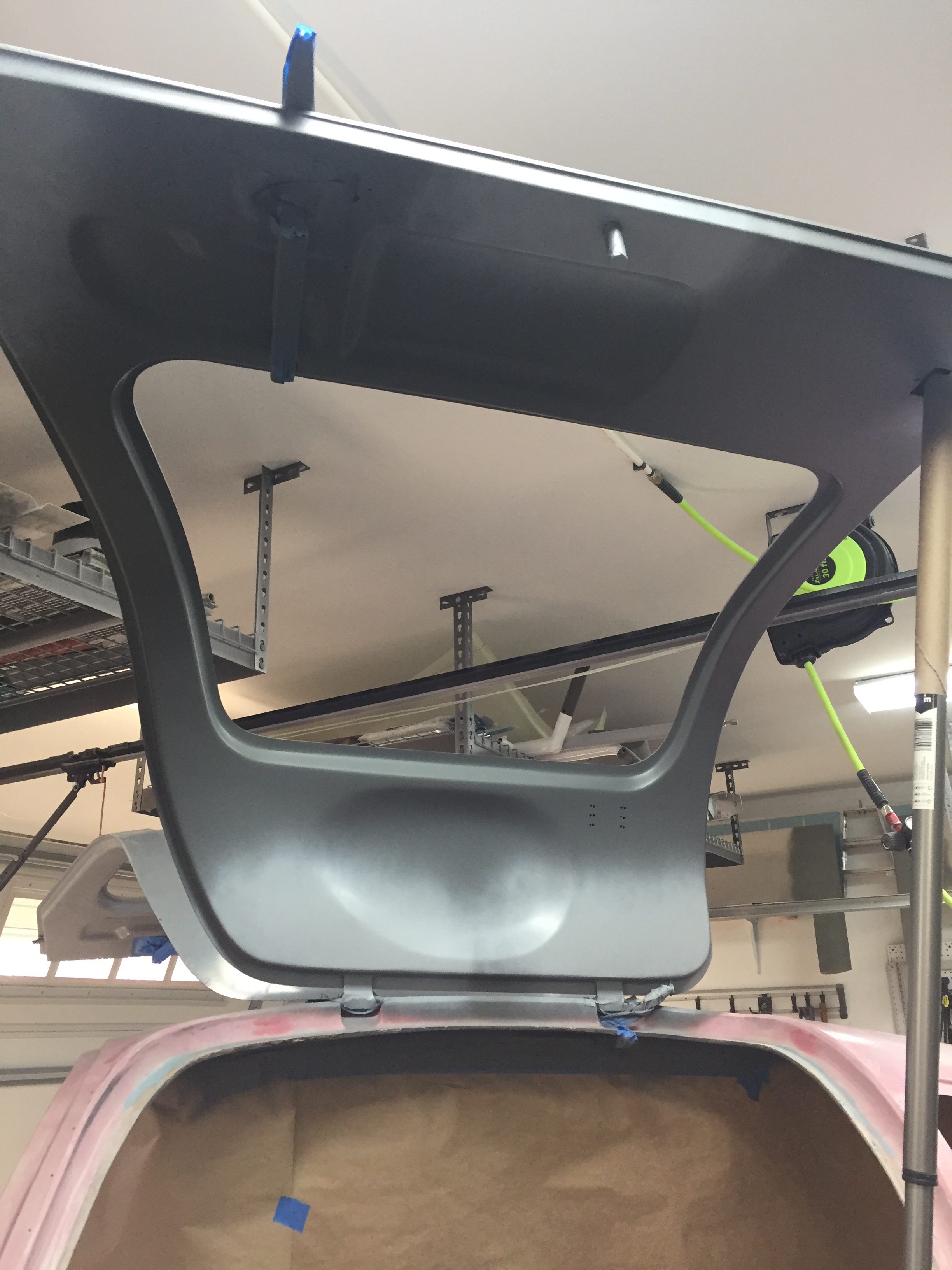
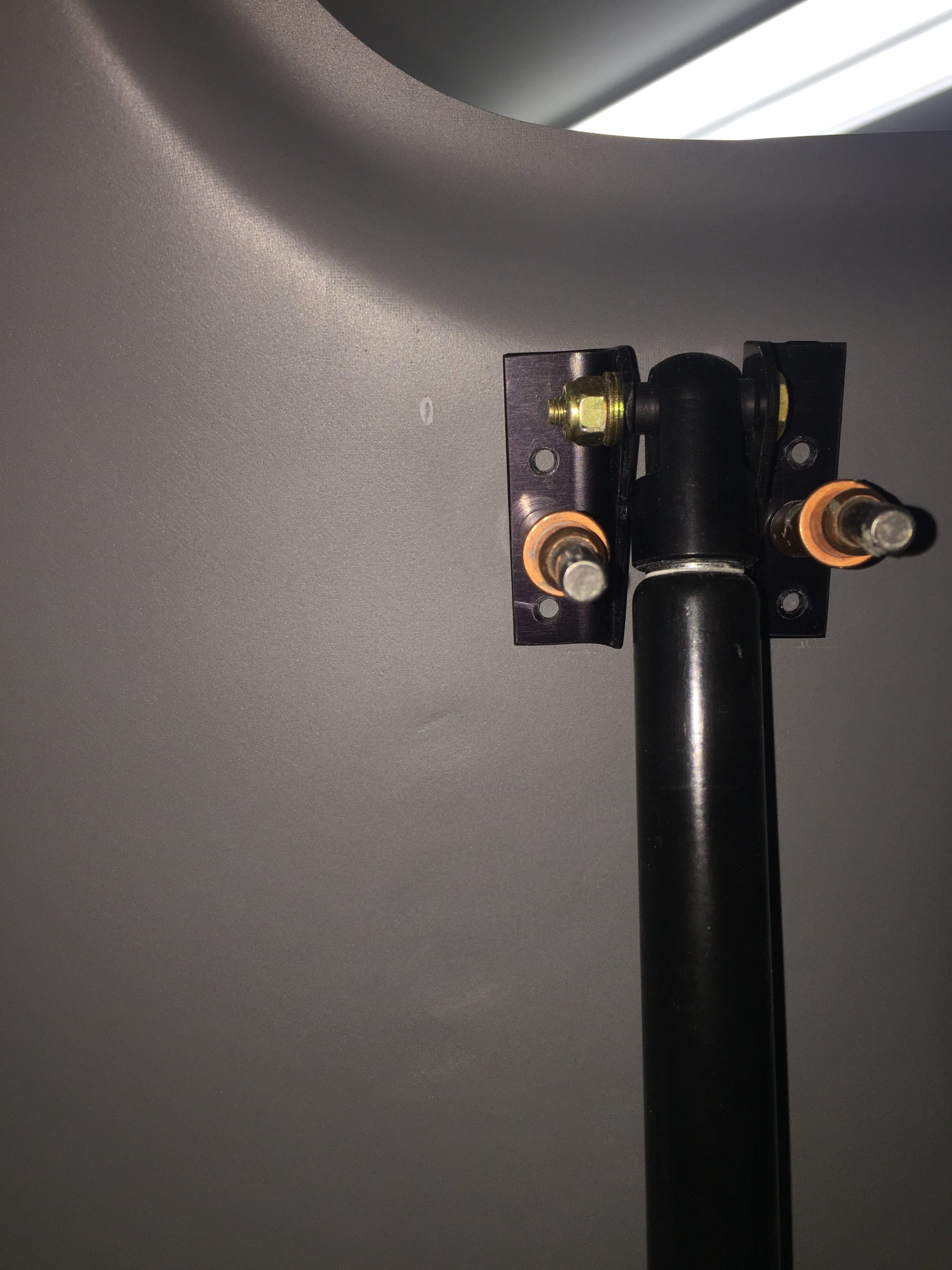
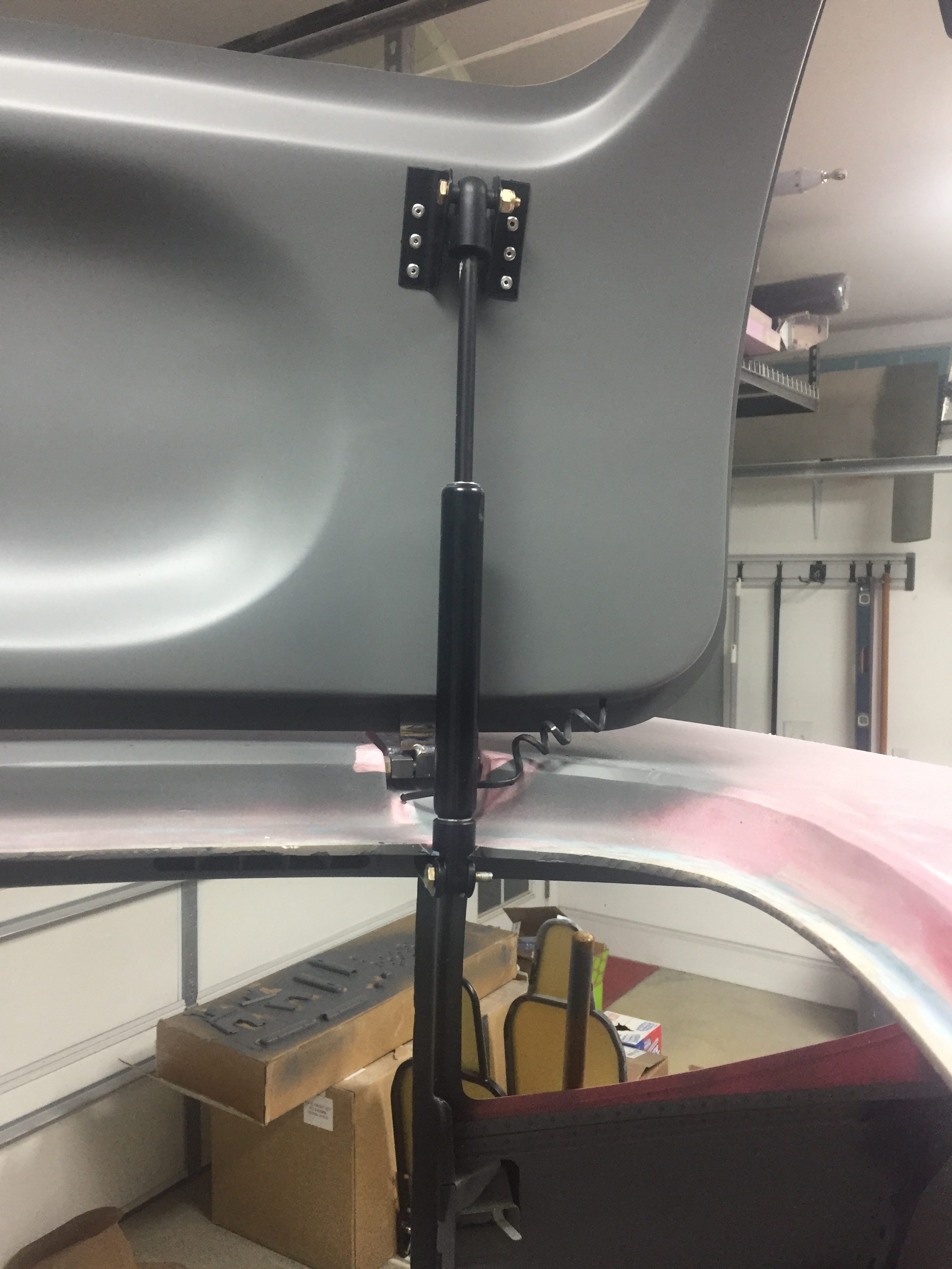
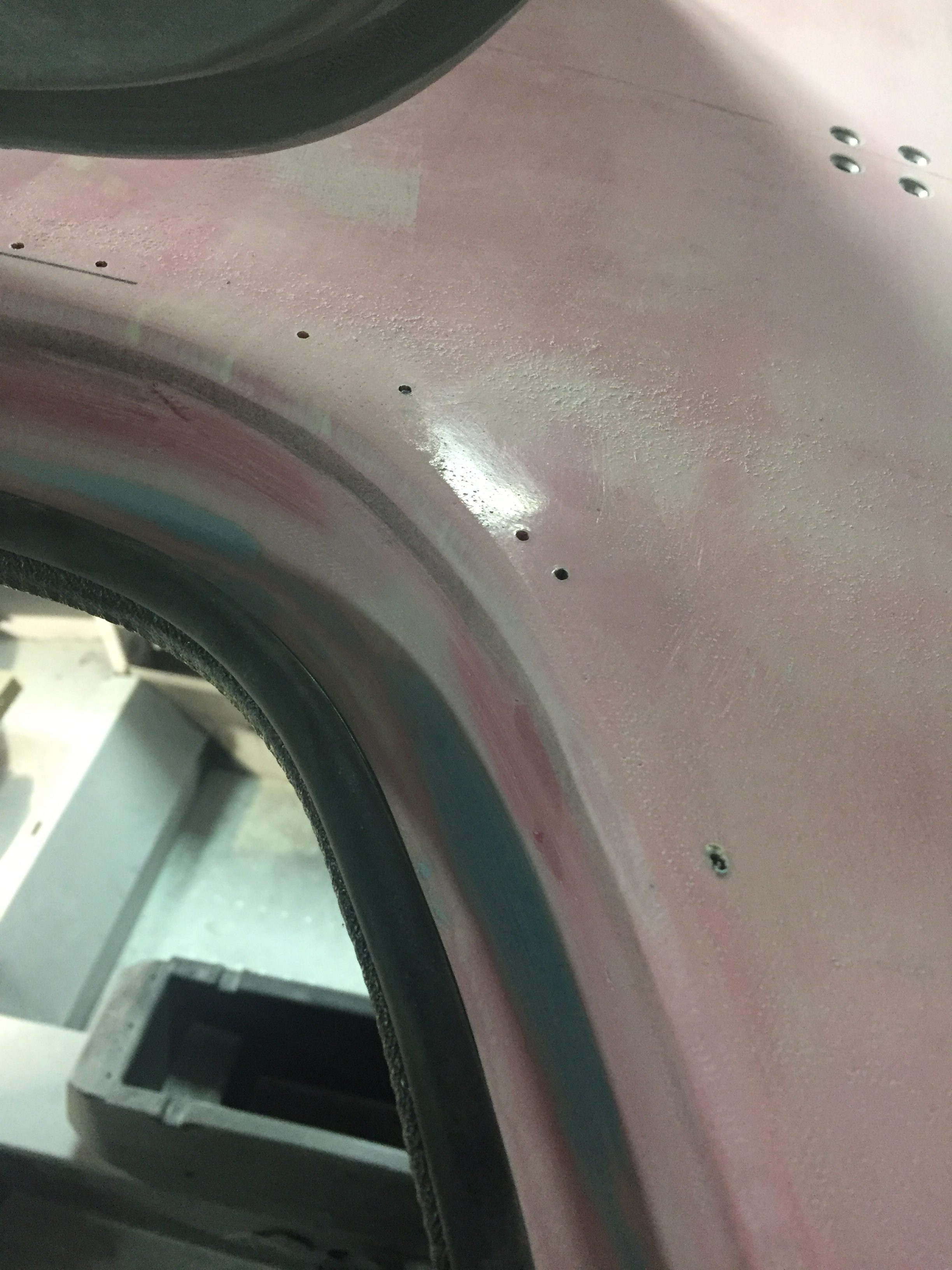
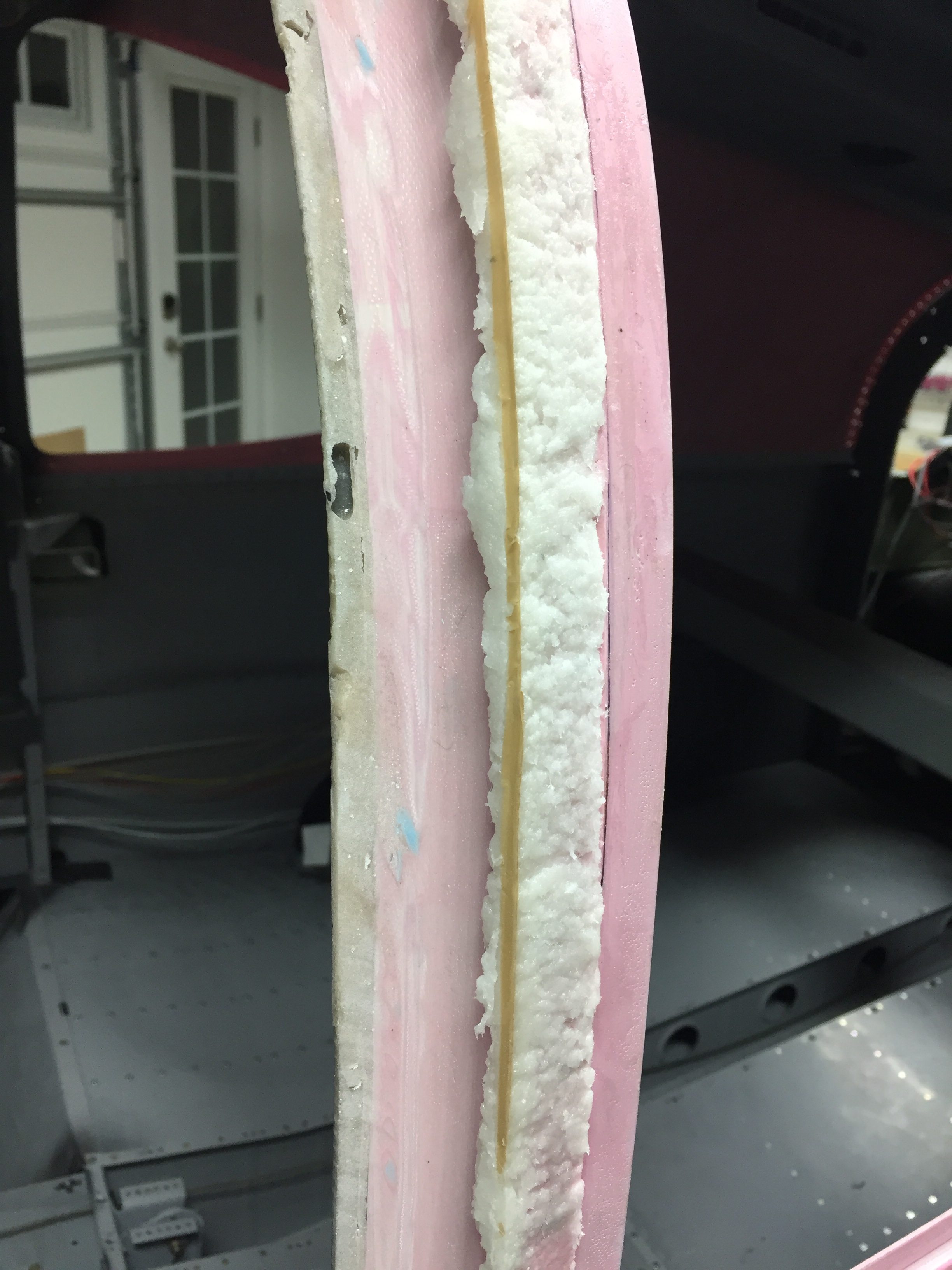
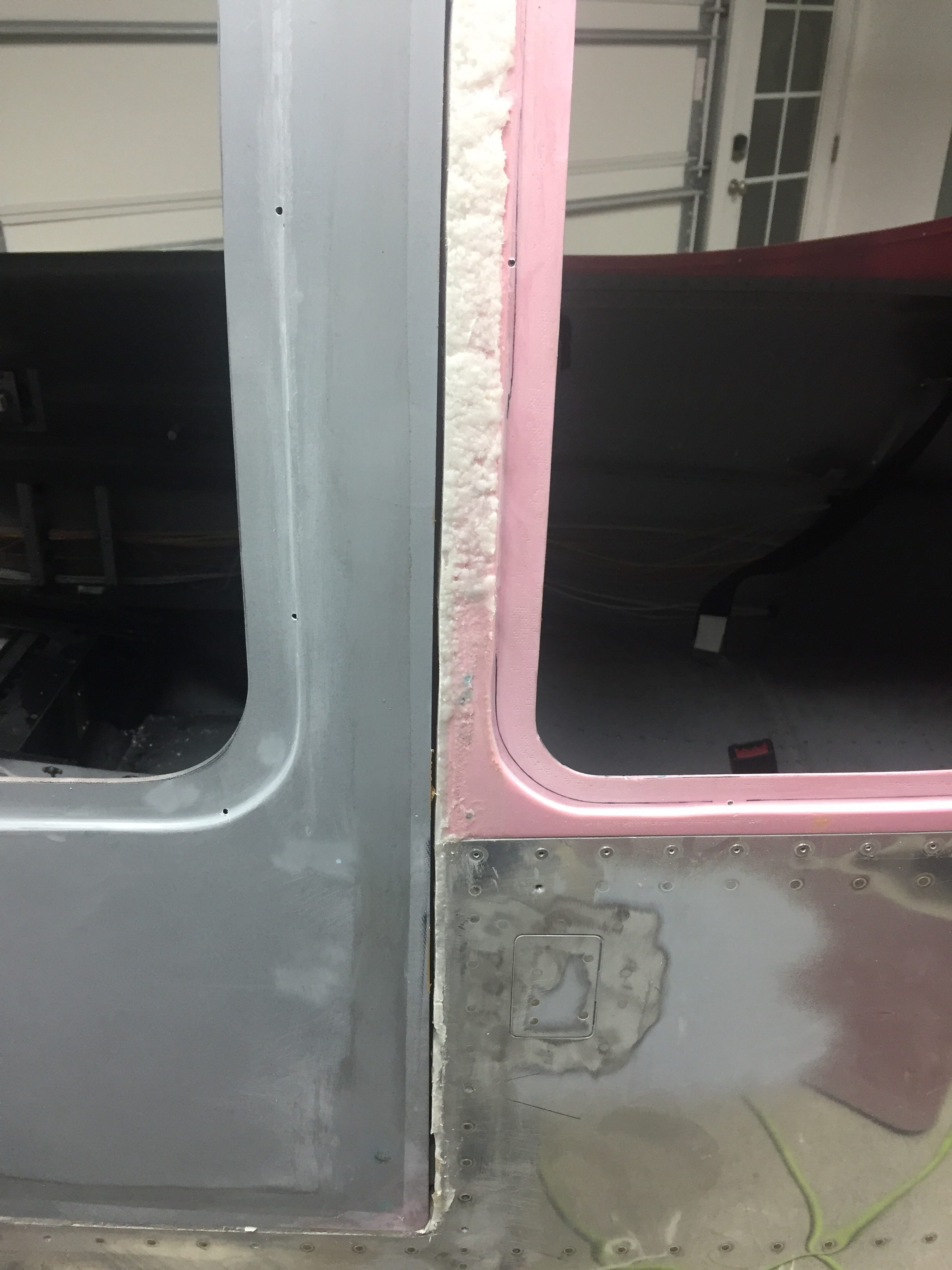
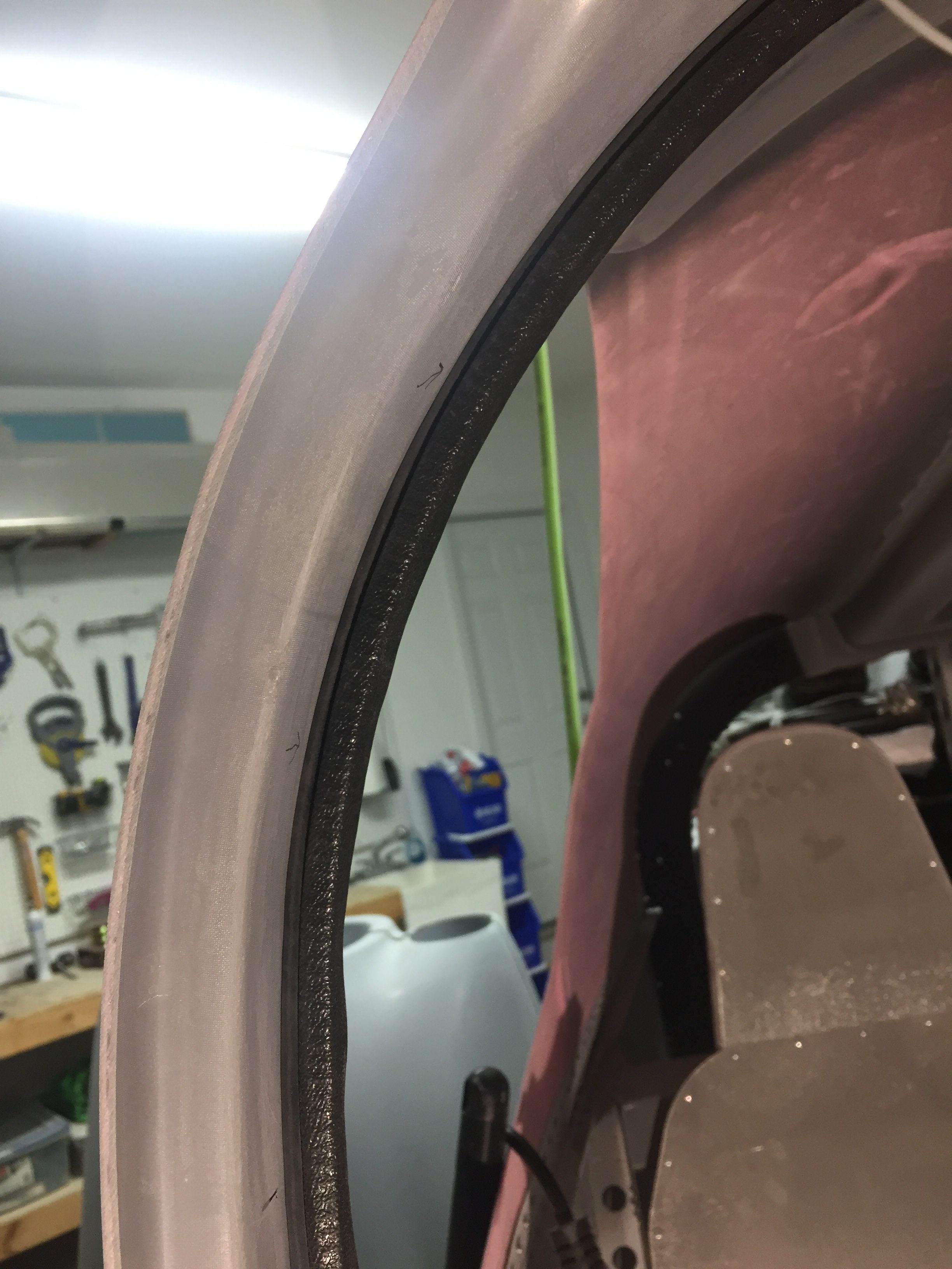
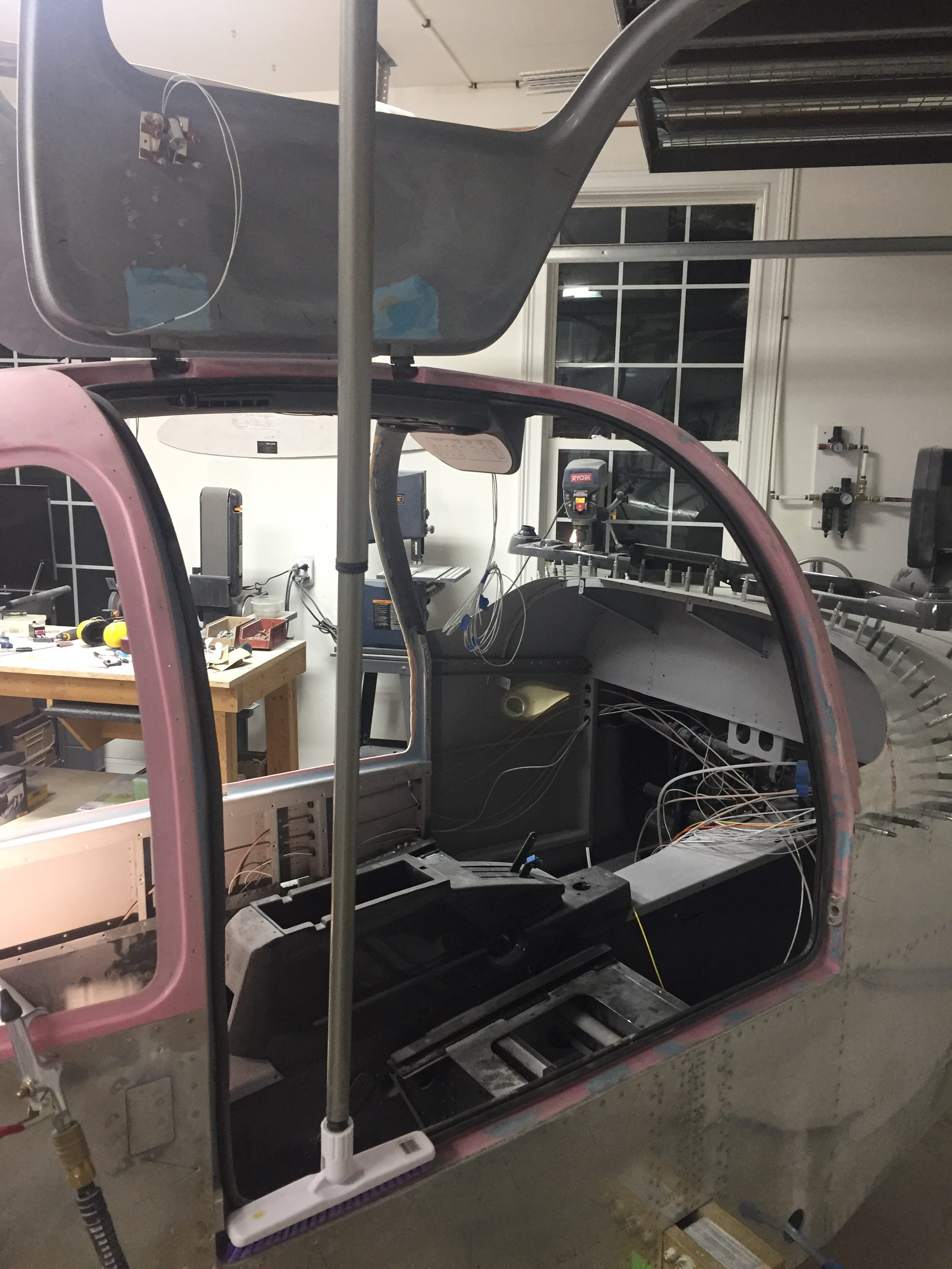
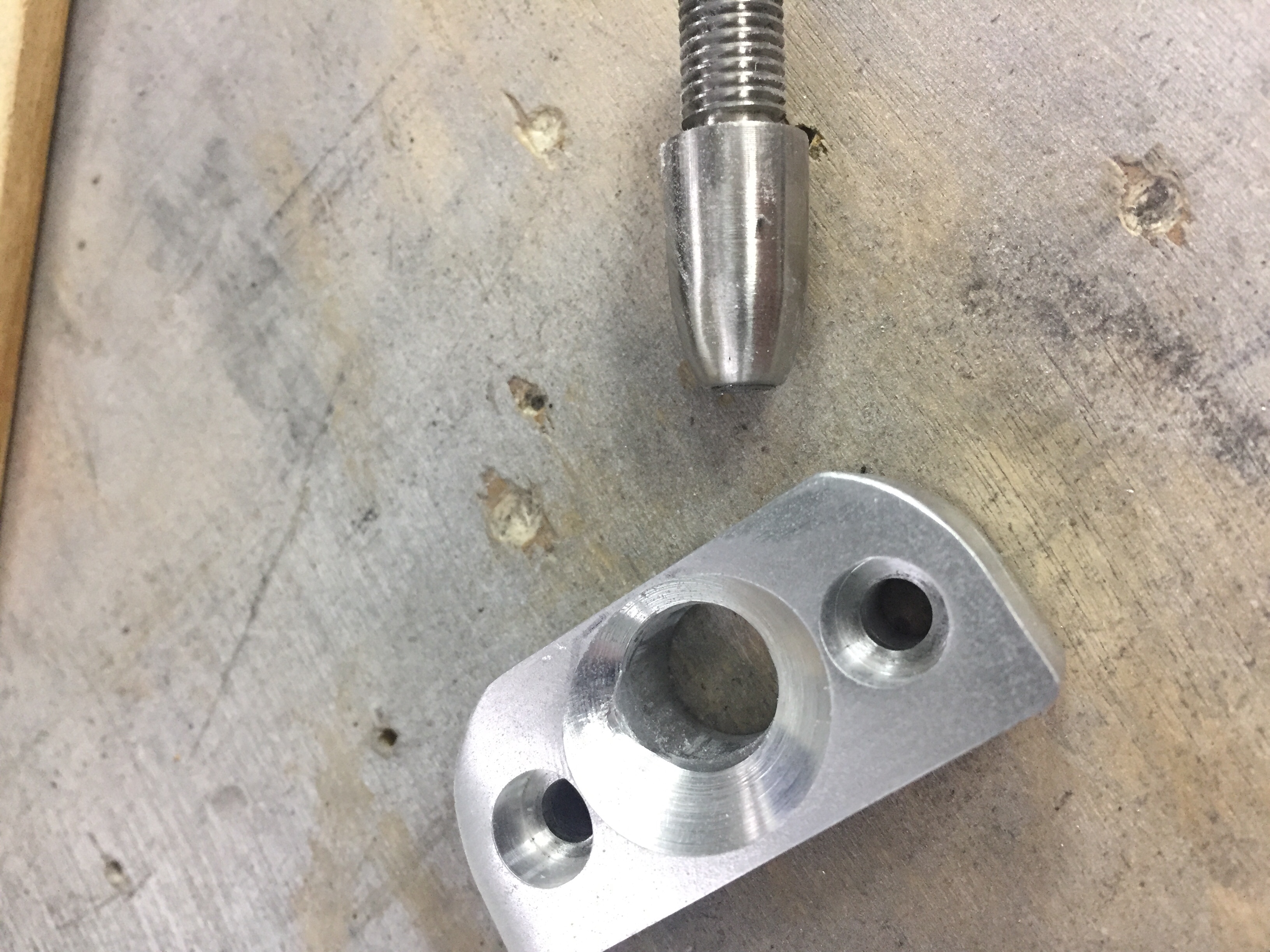
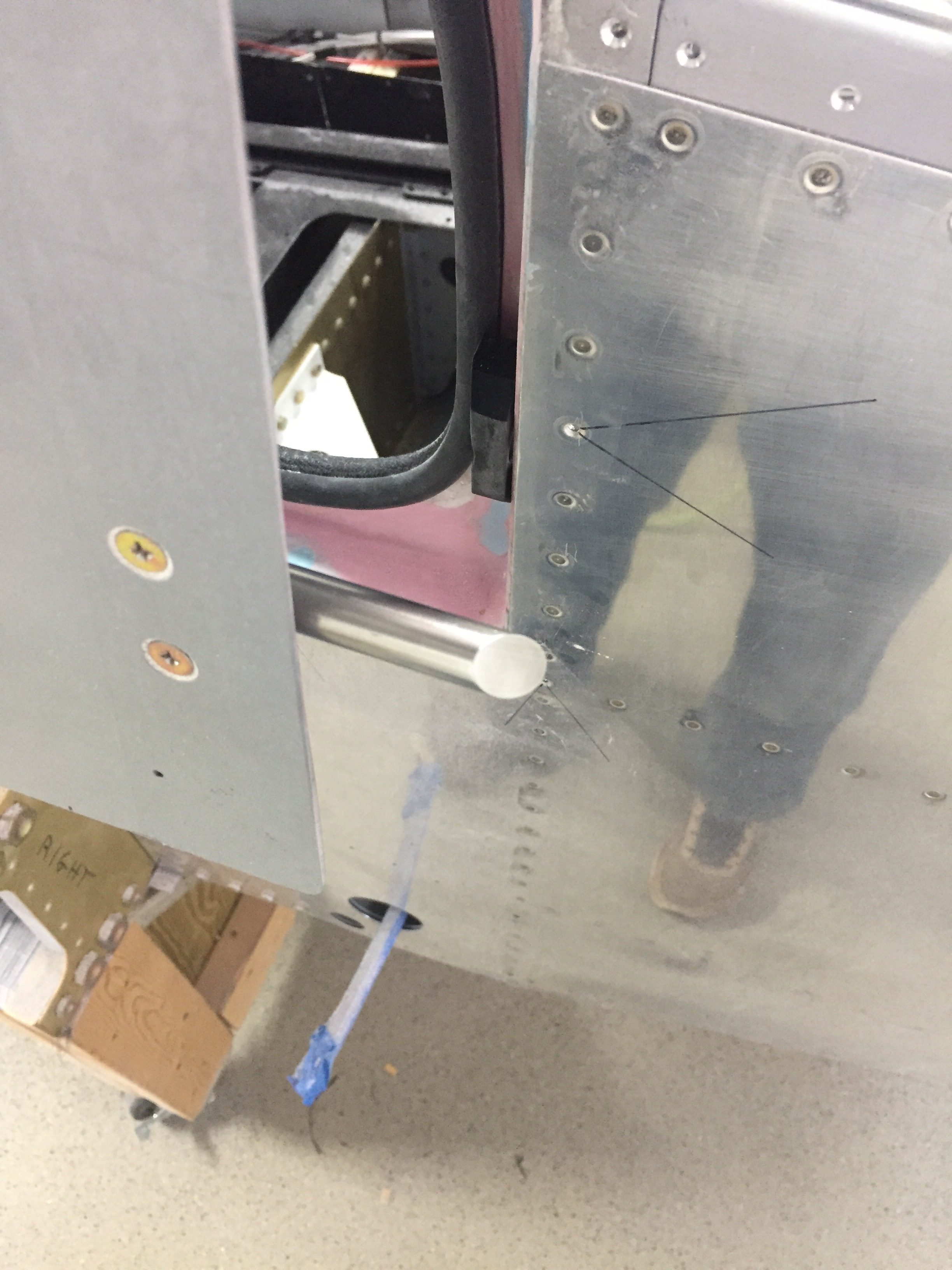
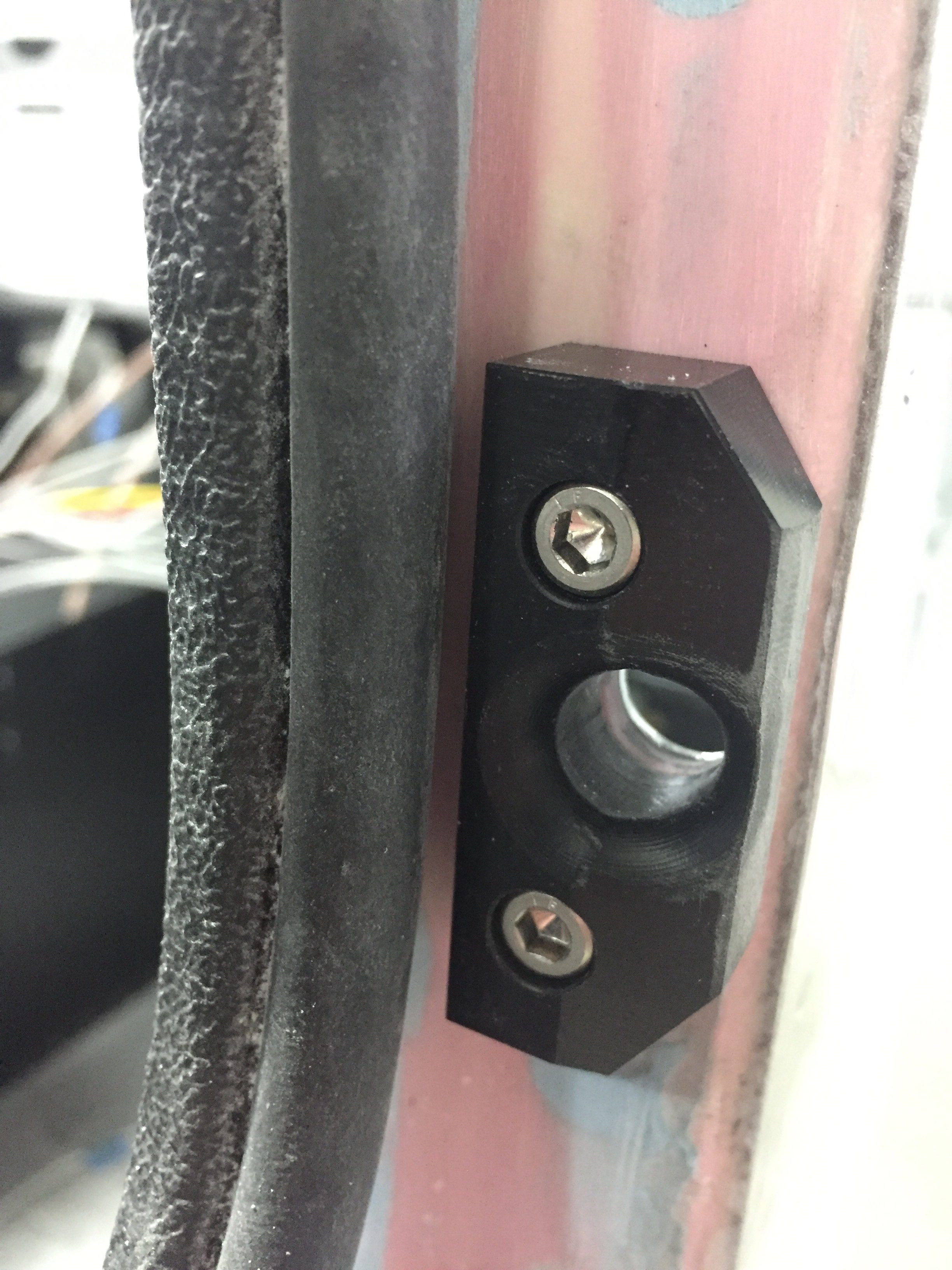
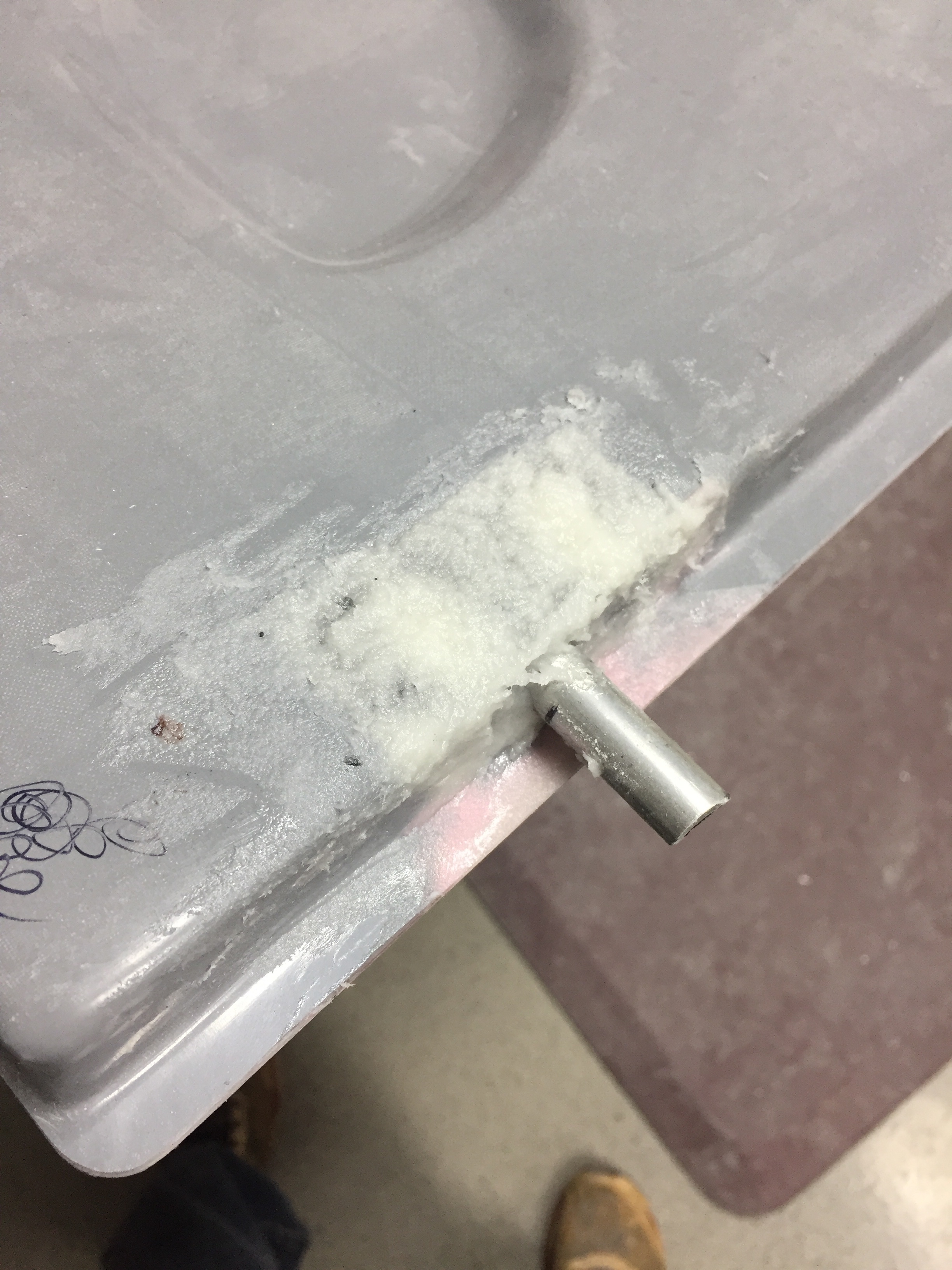
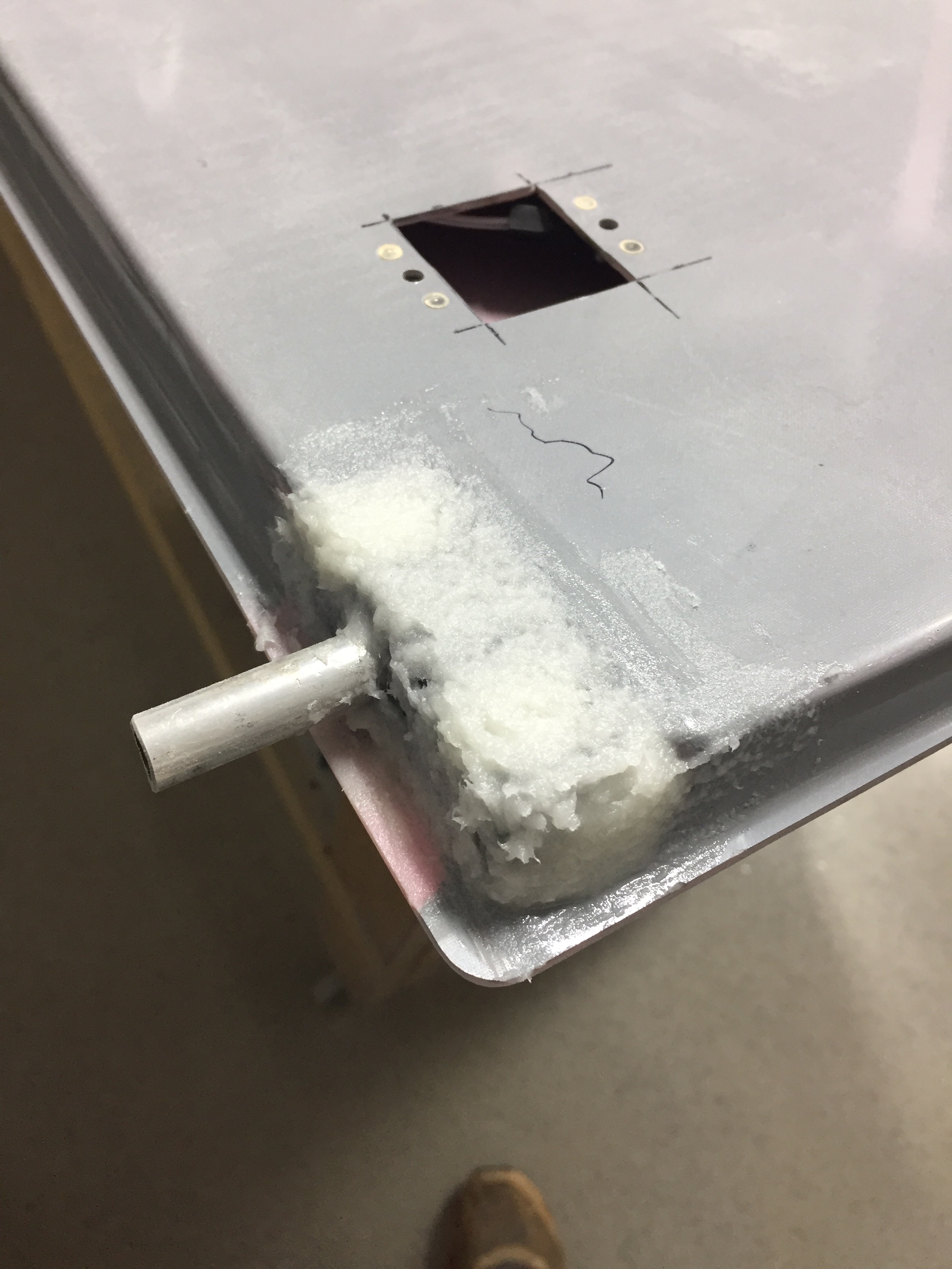
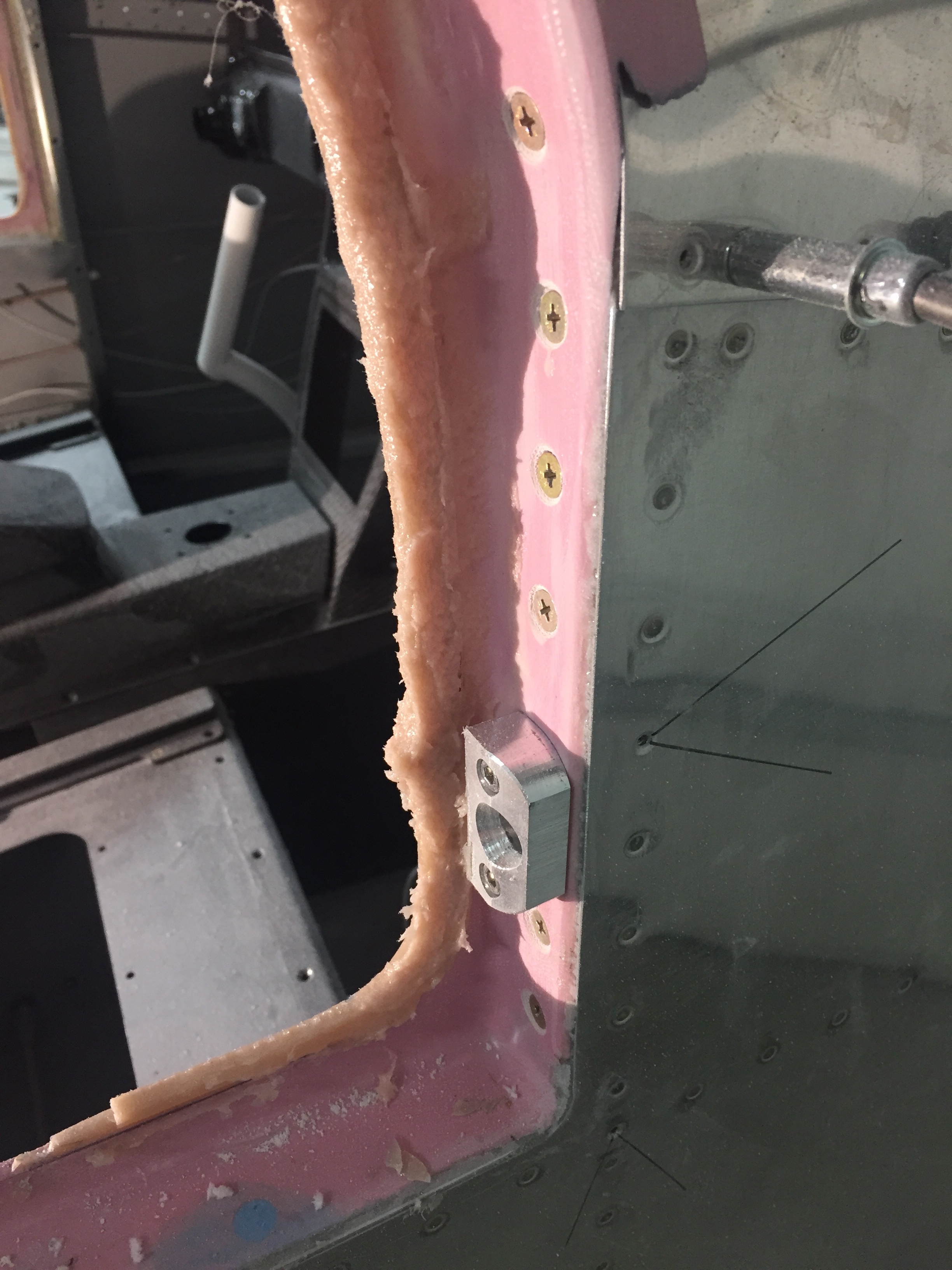
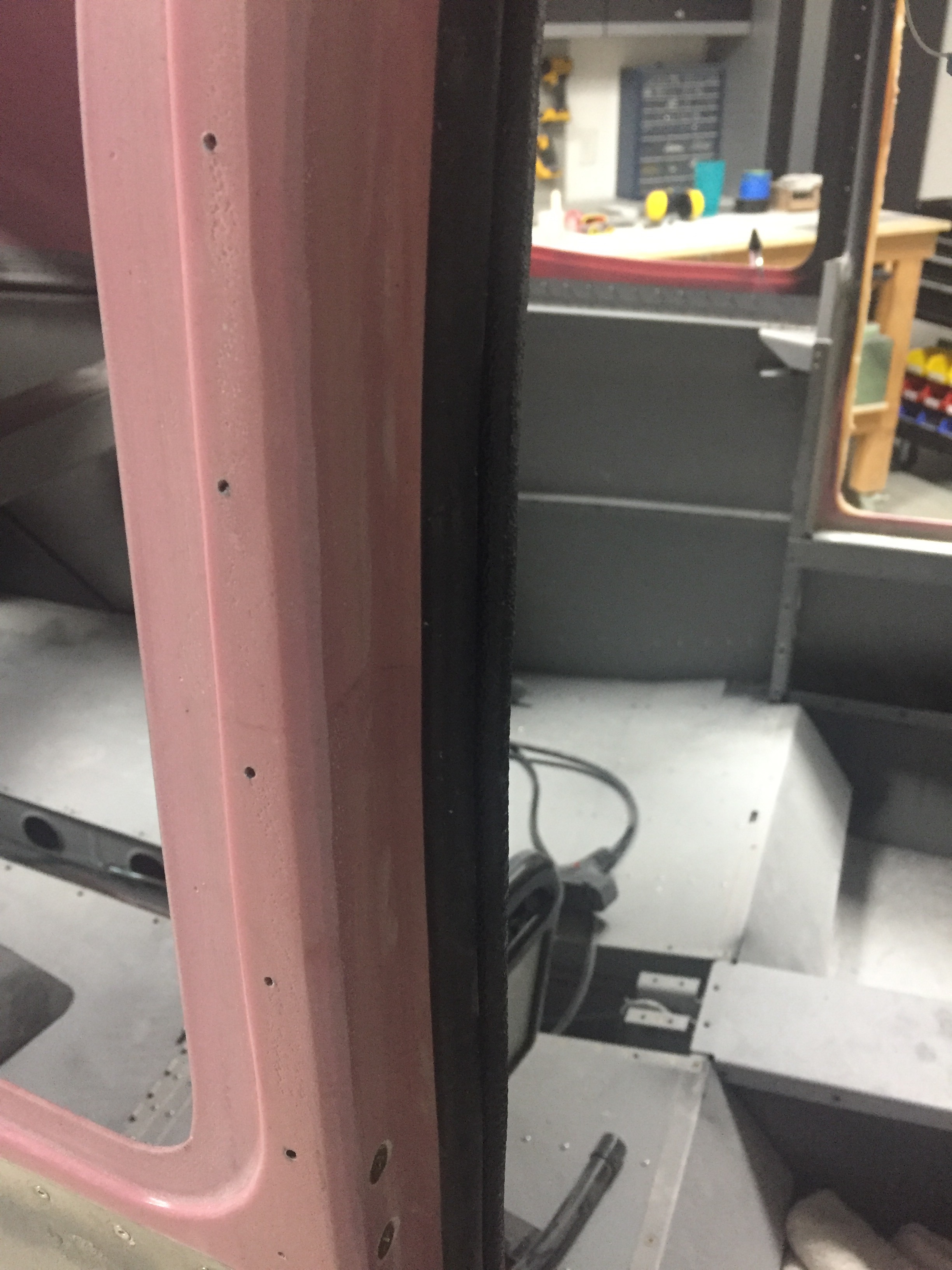
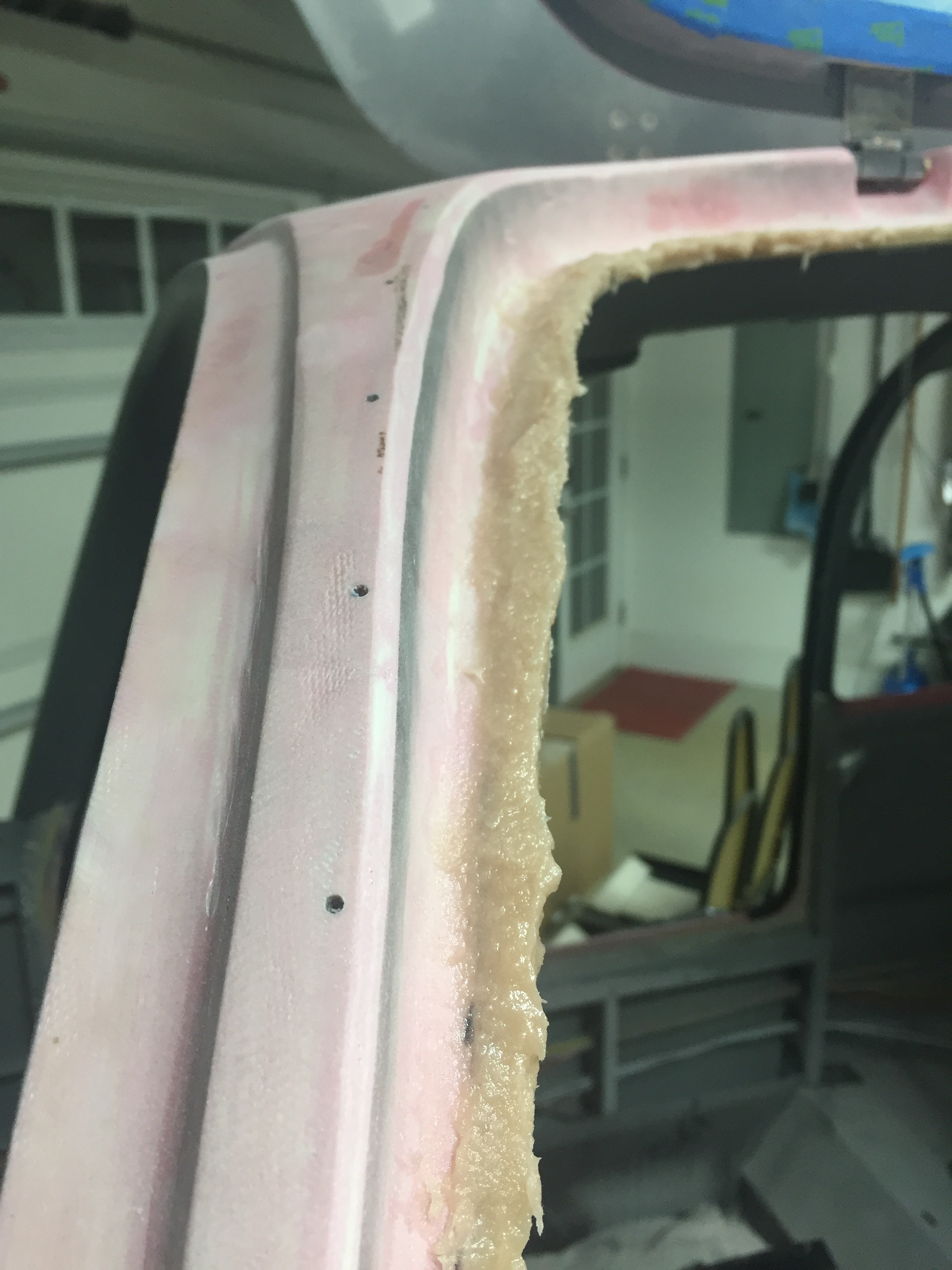
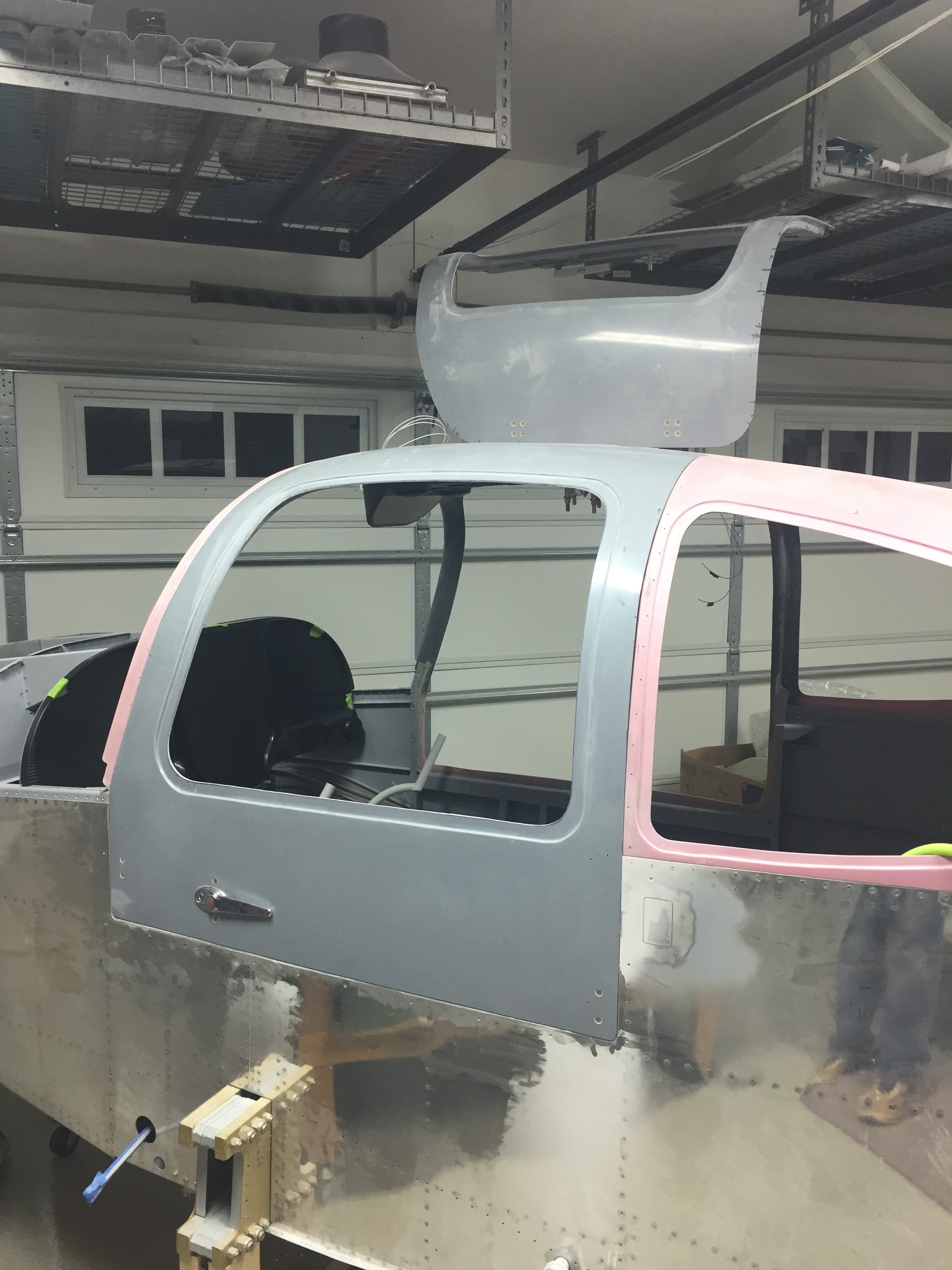
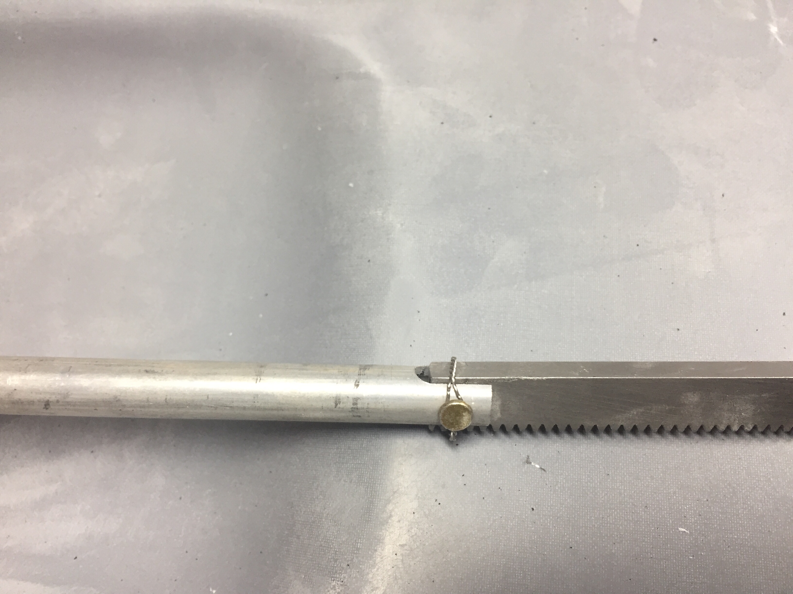
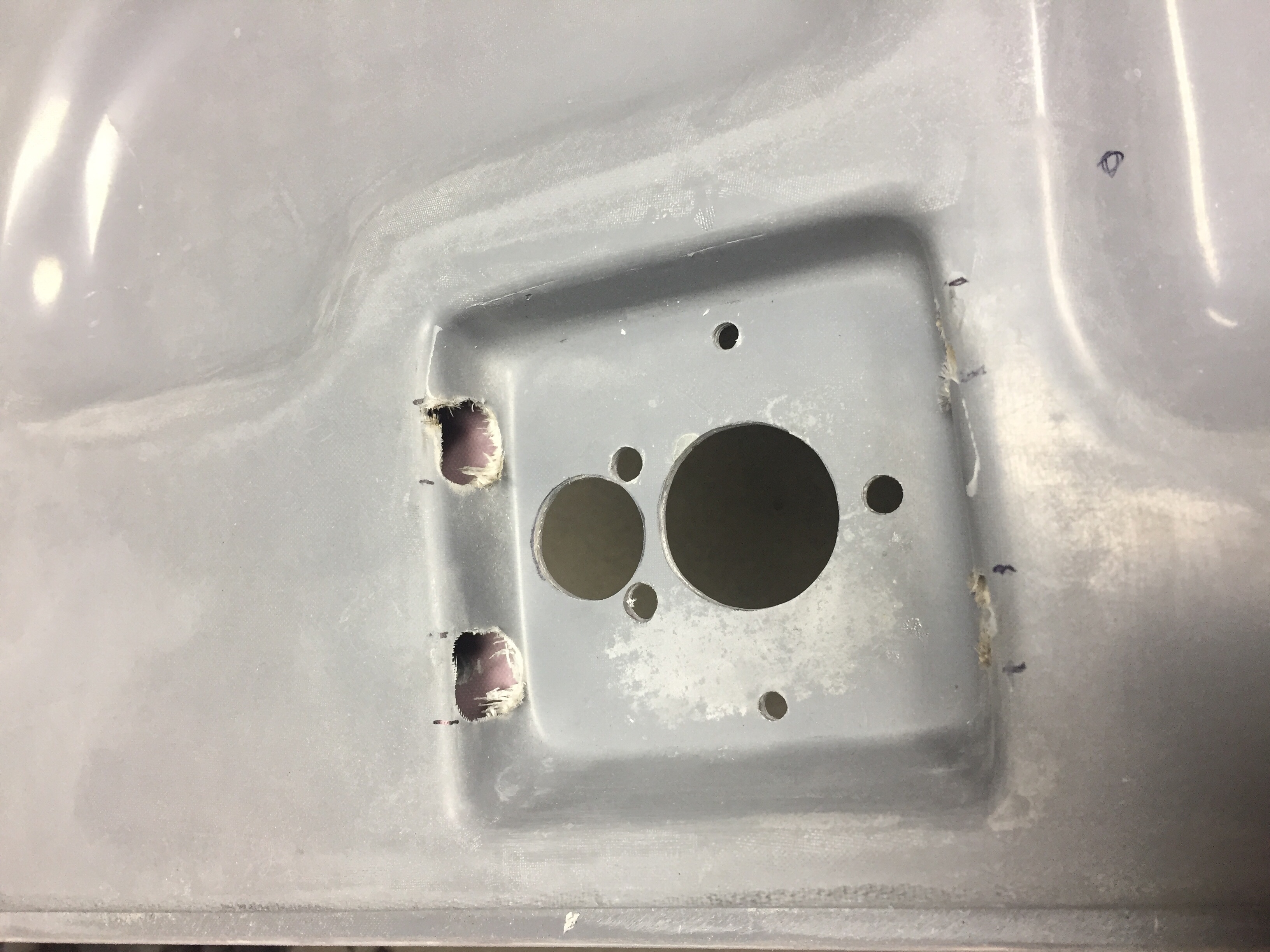
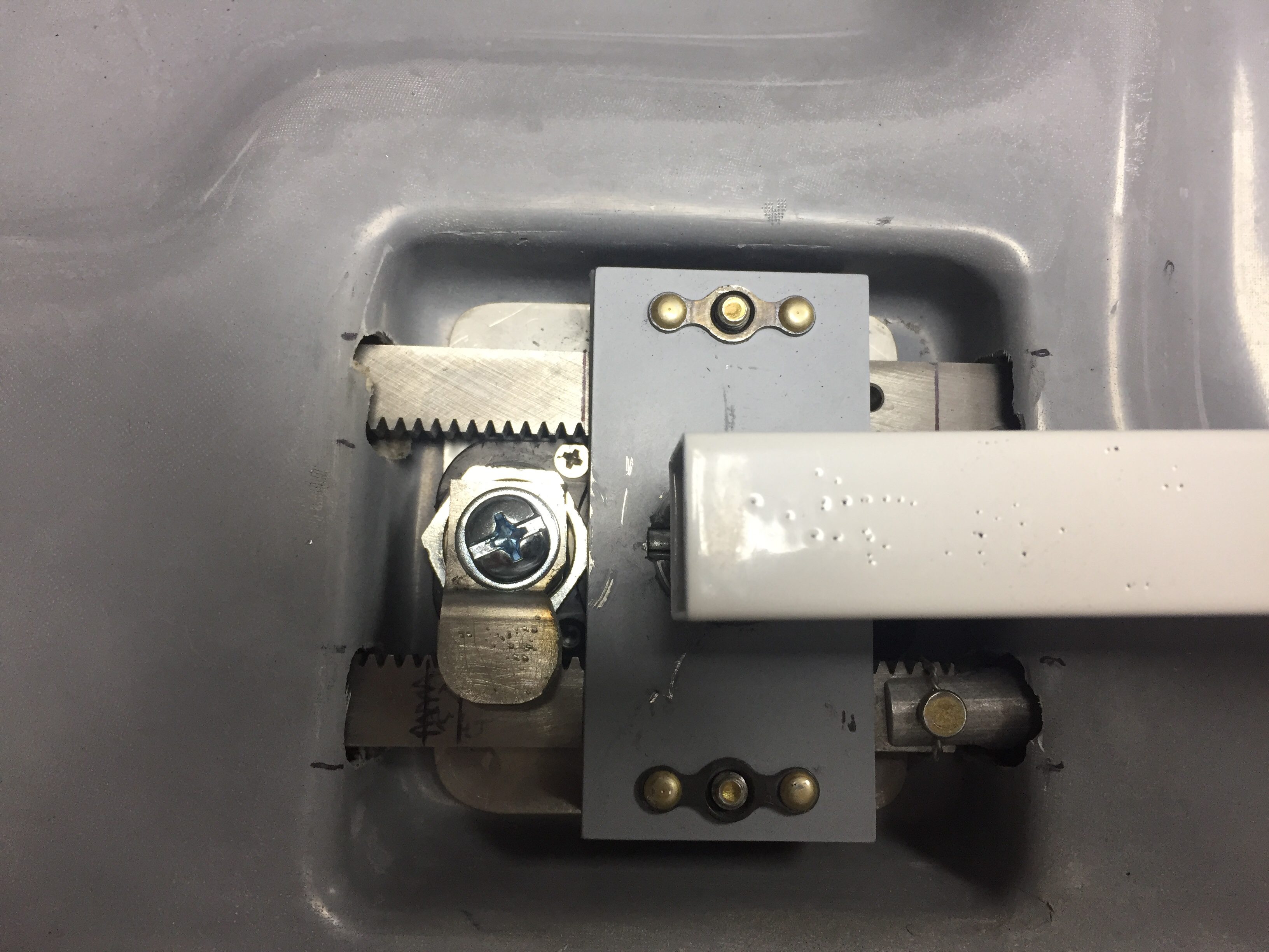
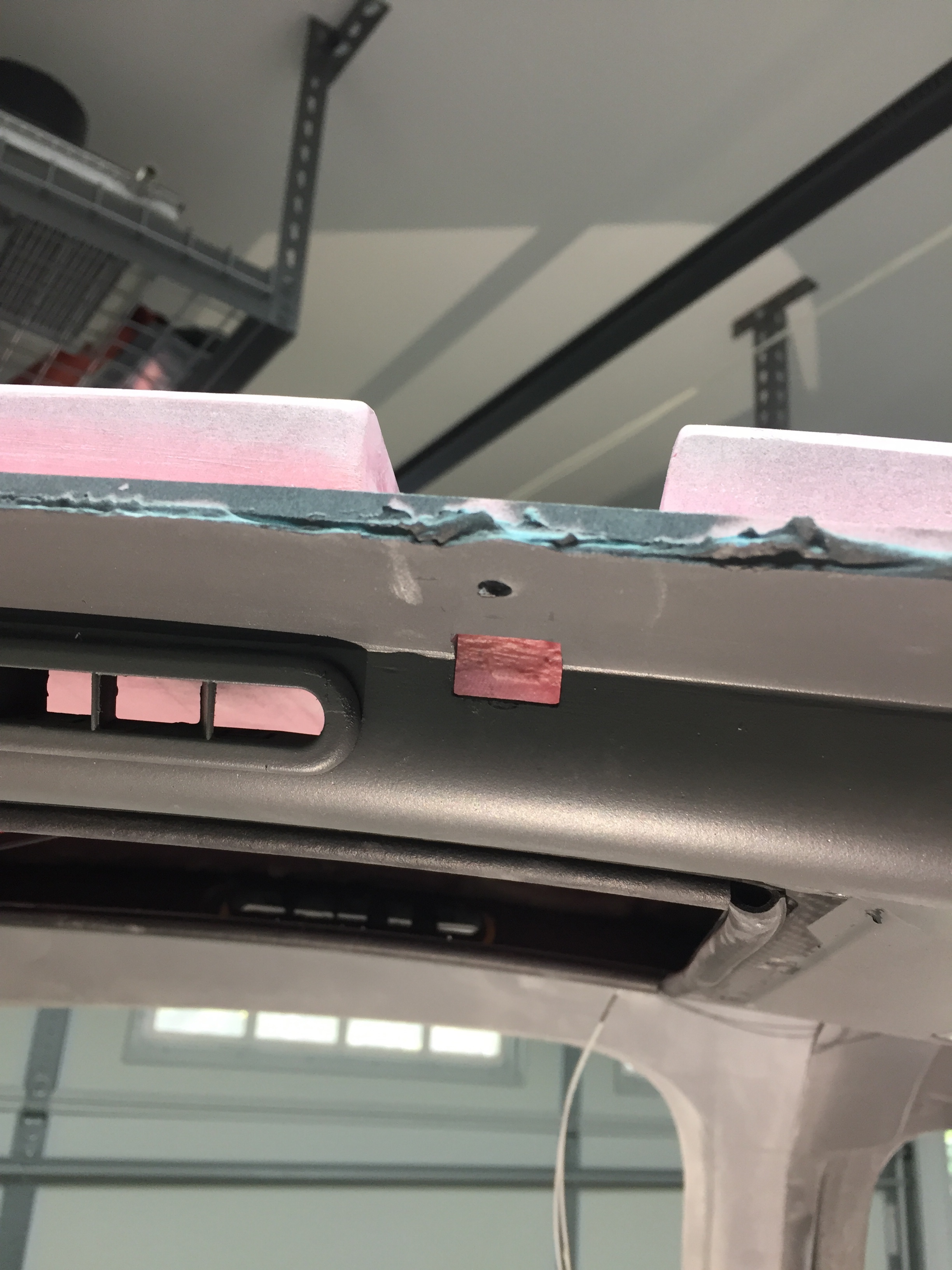
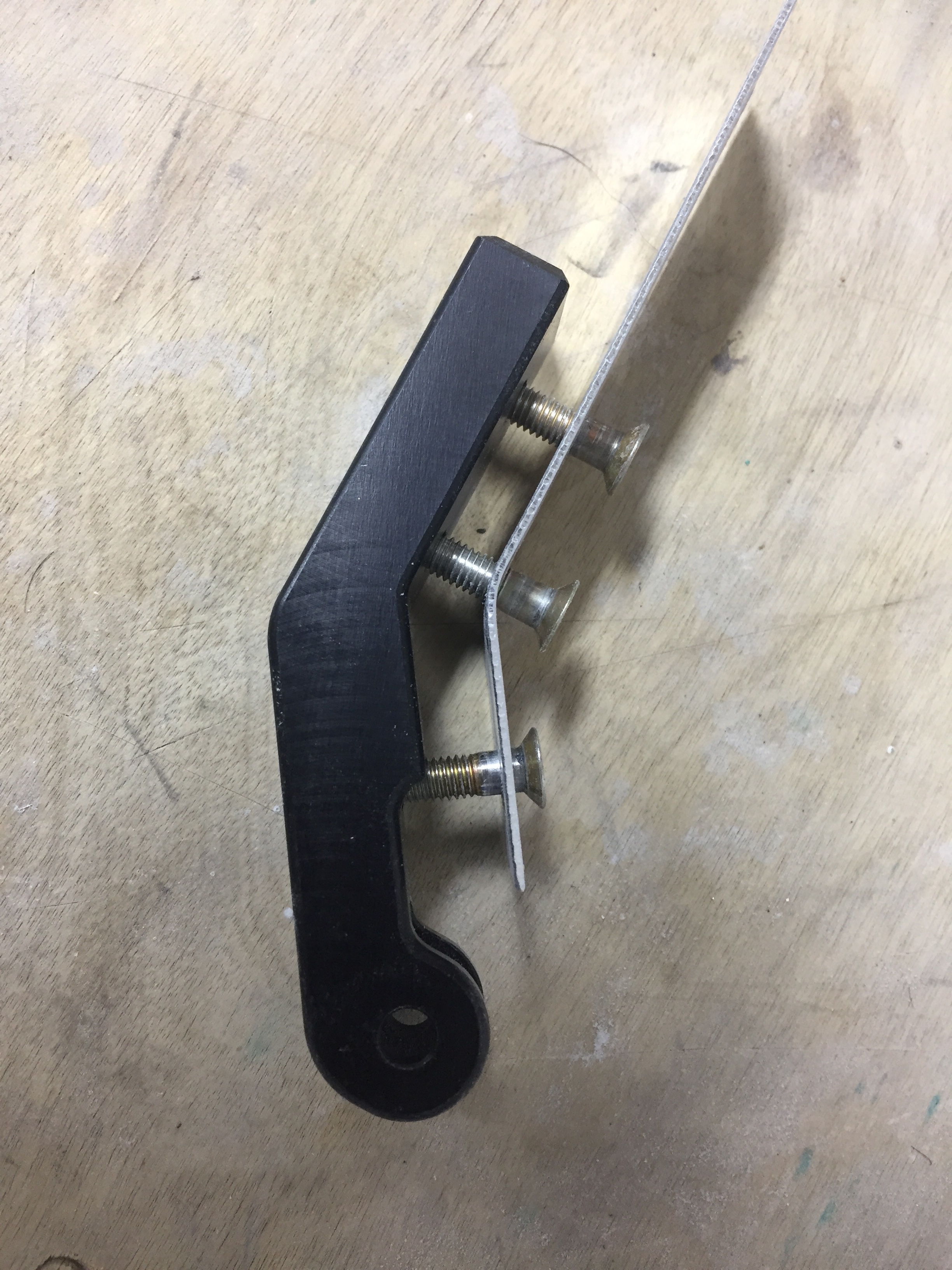
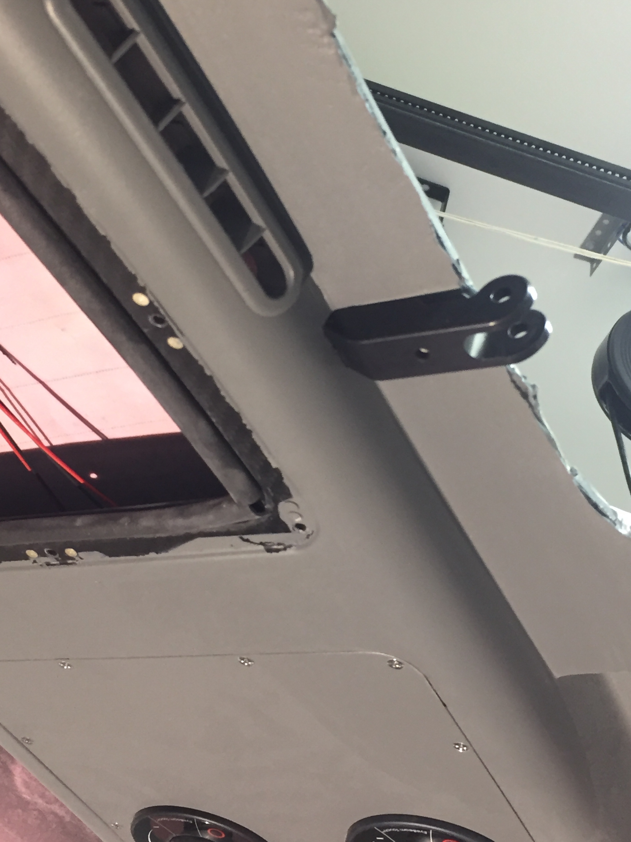
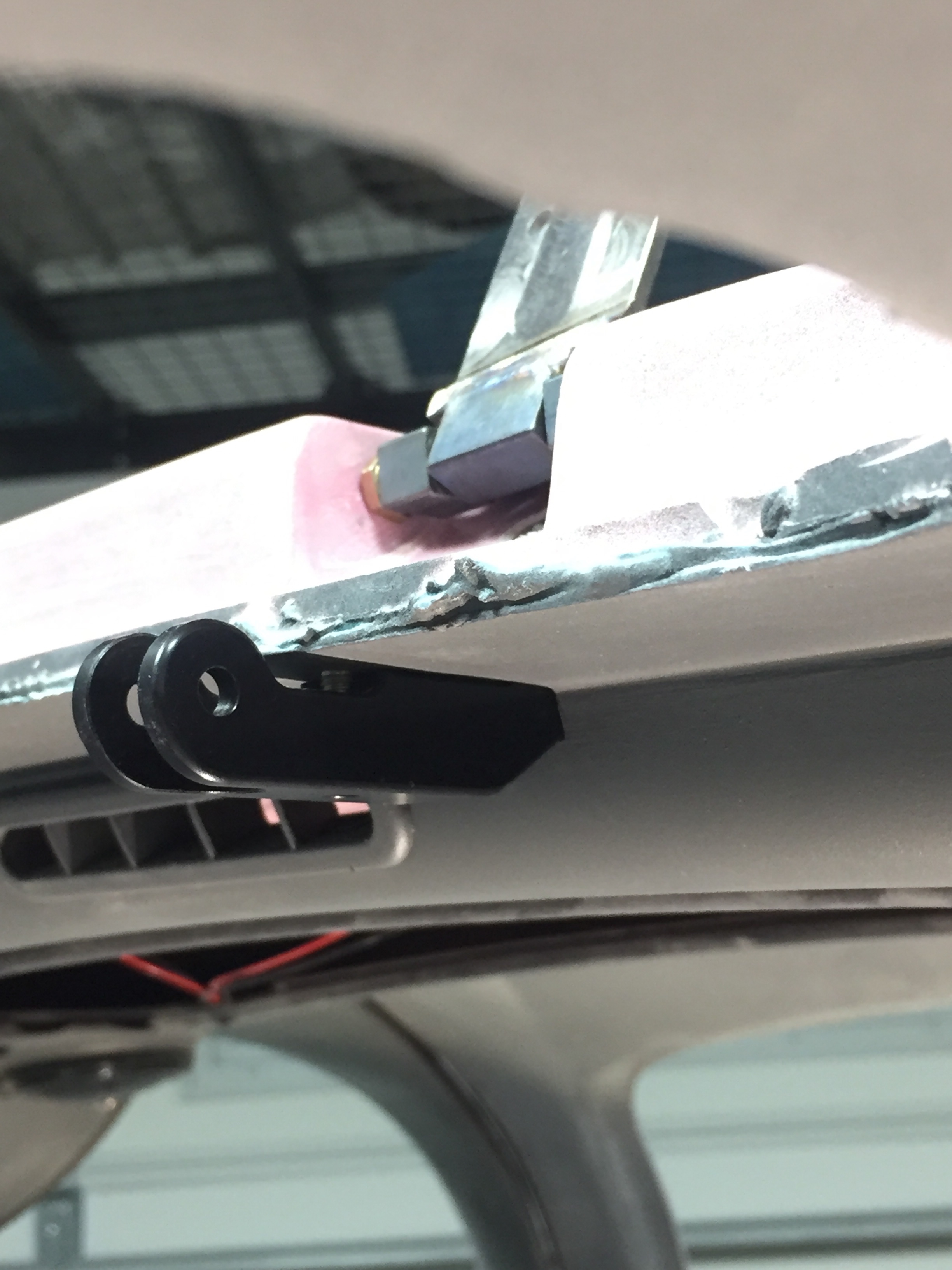
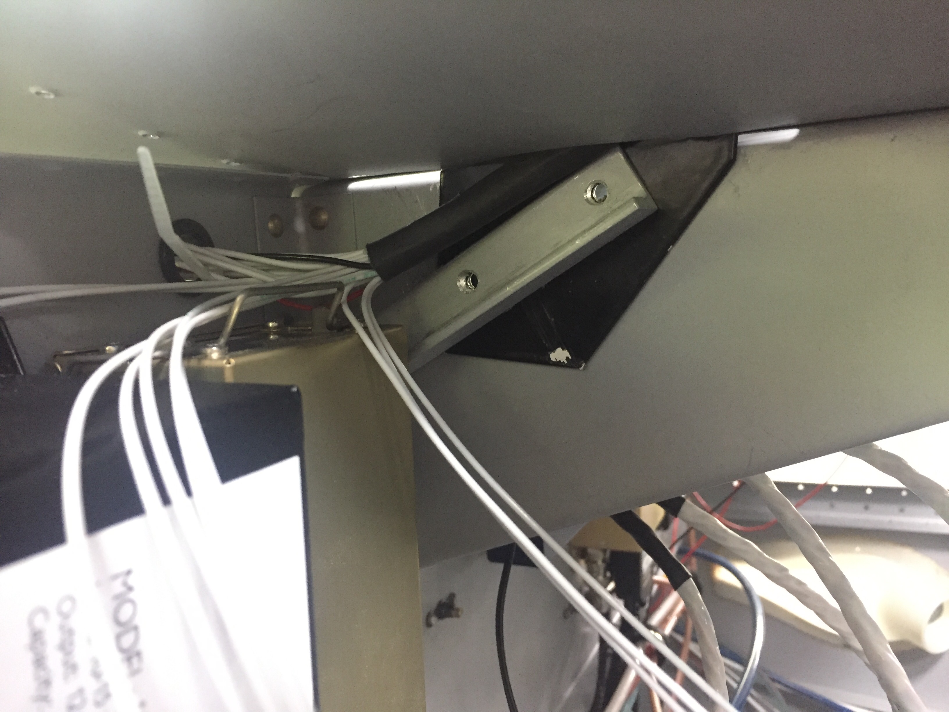
The last major task for wiring was the overhead console and lighting wire run.  The front structure (now in) and skin has to be installed before I can run the wires down the support bar (powder coated black with the engine mount).  I wanted to keep as much access open as I could to finish up the avionics so I worked out a way to bend the skin upwards by riveting the center rivet line only.  Laura came out to work her magic behind the rivet gun and assisted in getting the wires through the bar and the bar installed.  It was a bit tricky feeding everything through the skin but worked out well in the end.  I did elongate the slot in the skin since my overhead switch panel prevents the bar from going in at the bottom first.

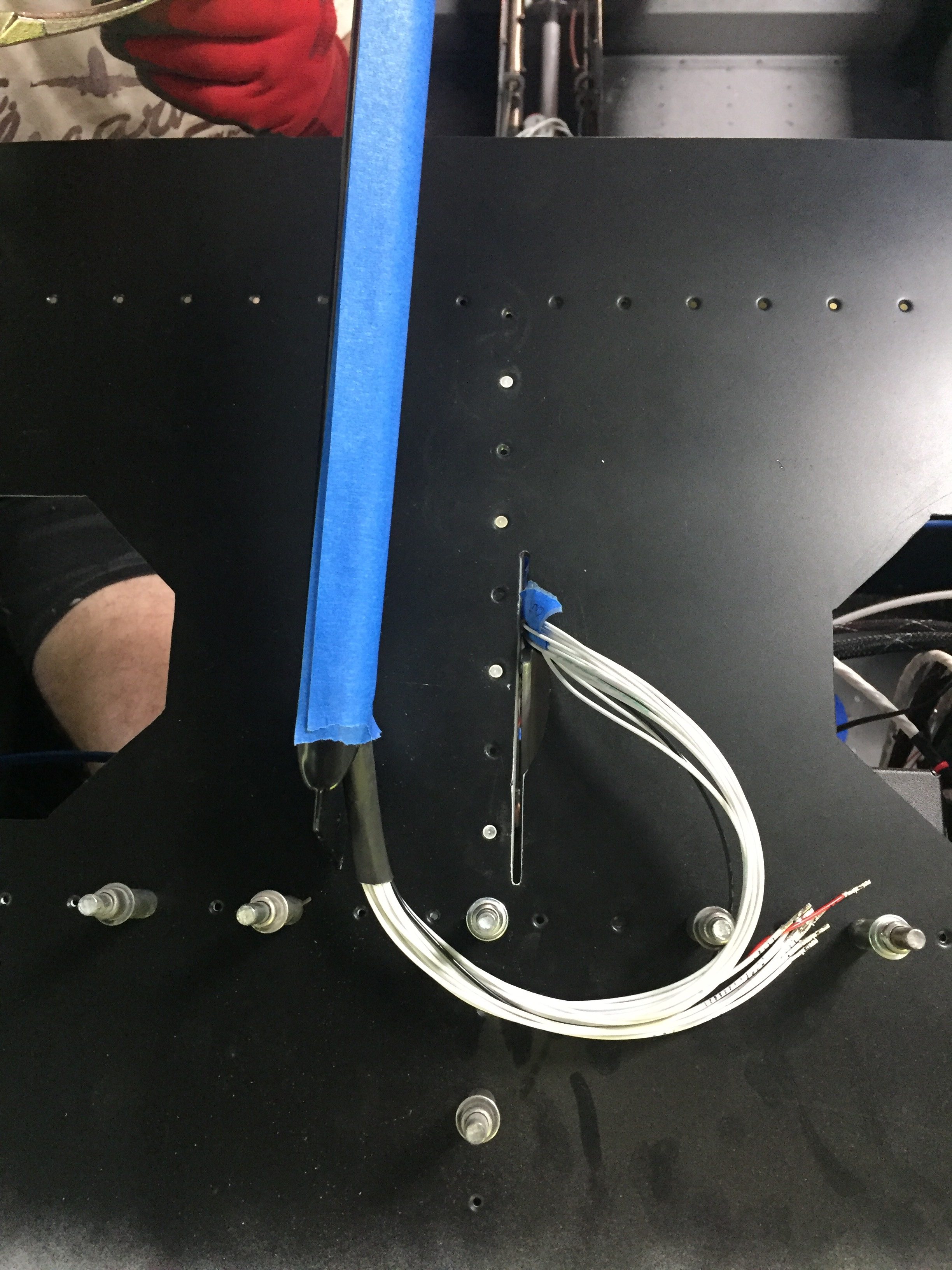
I set about connecting the wires from the overhead since I had already pre-routed them and installed terminals as needed since access would be difficult once the forward skin is in place.  Glad I did that, because I could never have pinned them out as they were after the skin and bar were installed.  The back lighting wires were all solder sleeved together to the power supply and the positive wires for the power supply, start switch, and O2 controller back lighting were all ran to the dimmer.  After a lot of observing and double checking, the only wires left unterminated are those going to the EMS/ECUs (I won’t have the ECUs until July) so nothing left other than starting to test stuff out!

The lighting control module (LCM) and instrument back lighting will be on the always hot bus so I was able to hook my bench power supply up to test it.  I was pretty nervous as there are a lot of complicated wires on the LCM and I was afraid of knowing where or how to troubleshoot an issue.  I shut the doors, turned on power and held my breath.  Opening the door should have turned all the lights on but it just made them flash.  The foot well dimmer was hooked up to the overhead and the back lighting didn’t work at all.  Fan-f**king-tastic.  Great start, Tim.

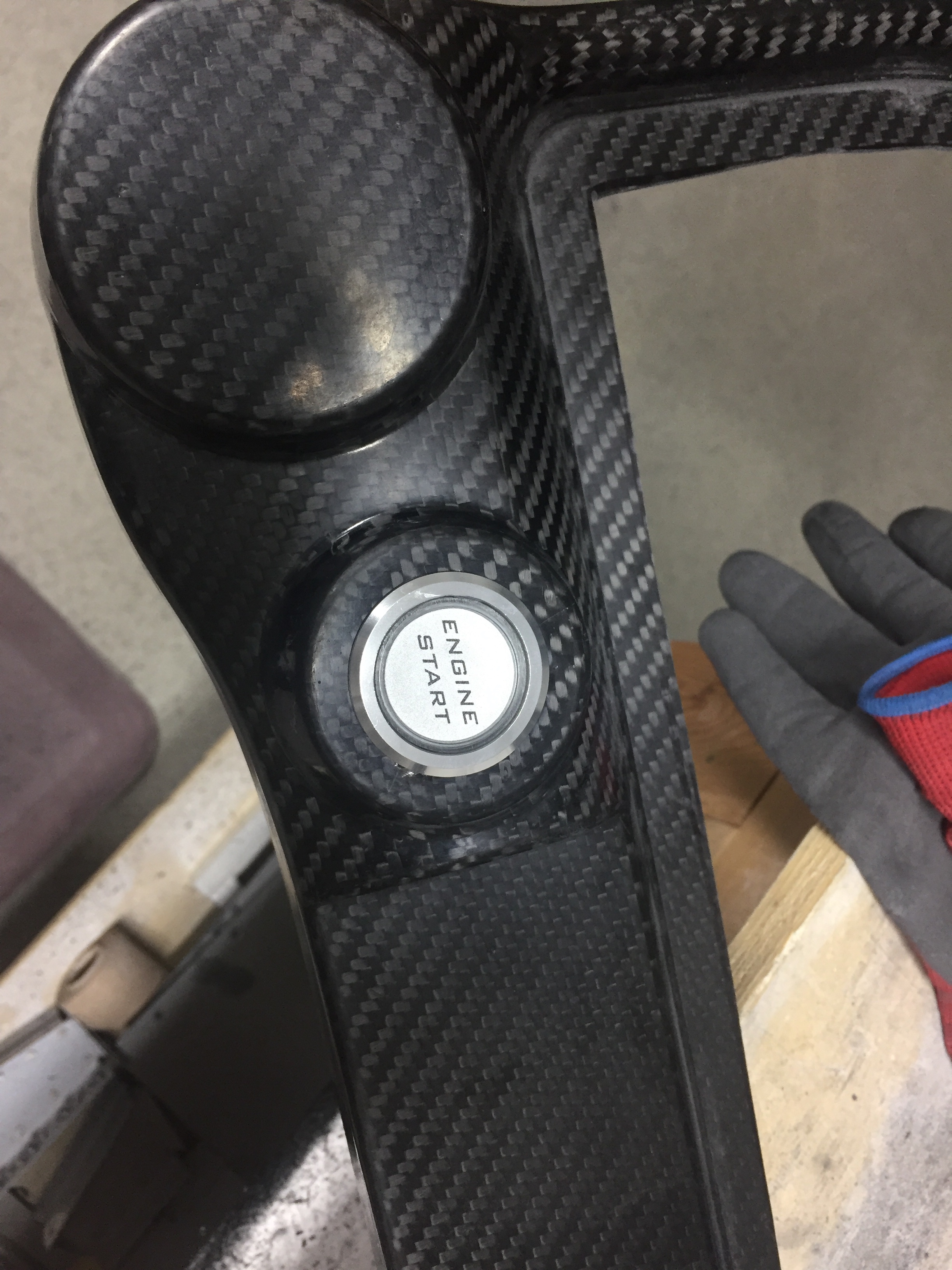
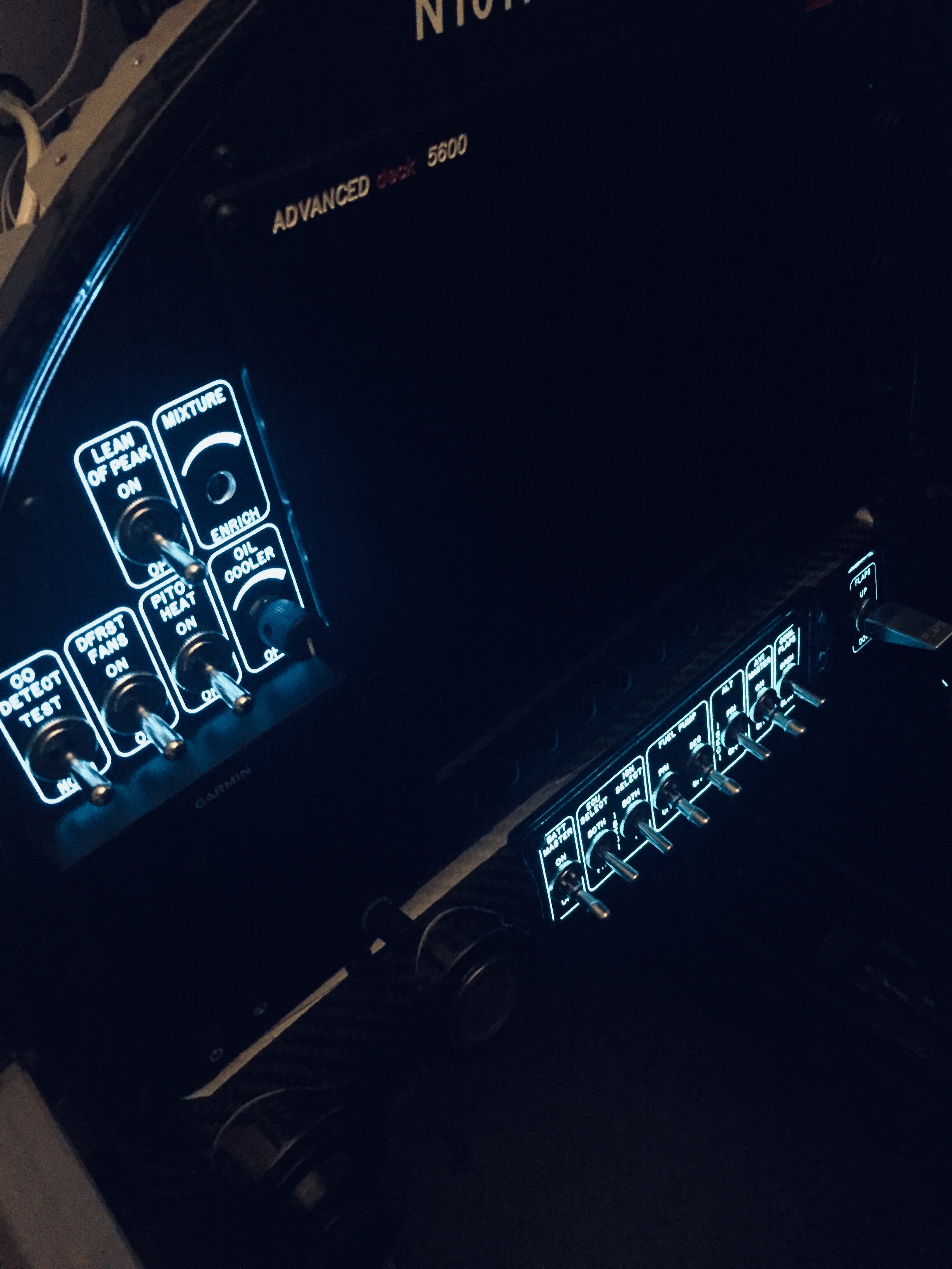
My skills at troubleshooting are more advanced than my confidence, and I was able to correct the wiring on the dimmer module (I had mislabeled the potentiometers) and figure out the back light power supply had a solder sleeve that didn’t solder all the way causing a bad connection.  Those were corrected and I had two out of three working.  The back lighting looks magical (yes, I said magical) and I sat in the dark for five minutes ooohing and ahhhing at myself.  The overhead dimmer and foot well dimmer circuits were now working and I could see how well Sean’s (Plane Around) LEDs illuminate the cabin.  The door lights and switches were still not working, though.  As soon as the door opens, I could hear the relay click causing the lights to turn off.  It turns out I had added an extra ground to the override switch and it was immediately overriding the timer in the LCM.  I corrected that and at the end of the evening got to see the fruits of my labor on the LCM as everything worked exactly like it should!

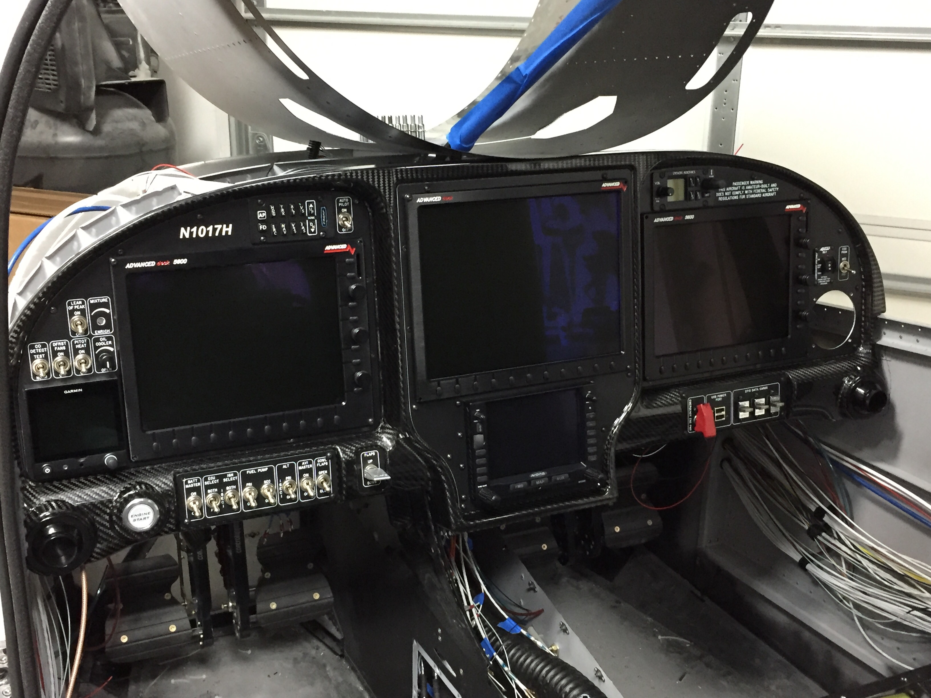
It’s finally time to slide all of the pretty glass screens in place and see what it looks like all fired up.  The cutouts on the panel inserts are exactly the size needed, so clearance was a bit tight.  Pretty soon, I had all three screens in place along with the IFD slid into the tray.  The G5 was installed and I hooked up the last two fittings for the pitot static system and got the tubes plugged in.  The PFD was a tight fit and required several attempts and getting all the wire bundles situated just right on the ACM to allow the connectors from the screen to fit without crimping.

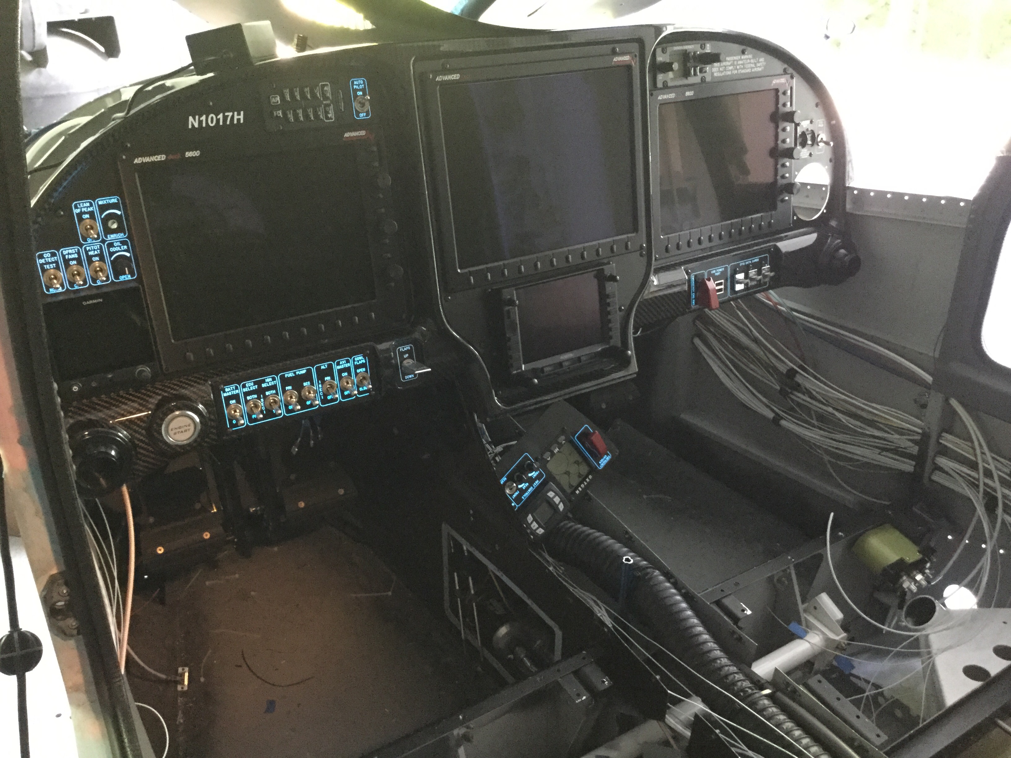
Man, does this panel look awesome!!  I have spent literally years designing the layout and dreaming about this very moment.  I couldn’t be happier with the way it turned out.  I’m really looking forward to sitting behind it and having great adventures with a massively capable avionics suite that is just as suitable for fun VFR flights as it is hard IMC.  The carbon is a great look, the overlays are perfect, everything is in reach, and it is a real show stopper!

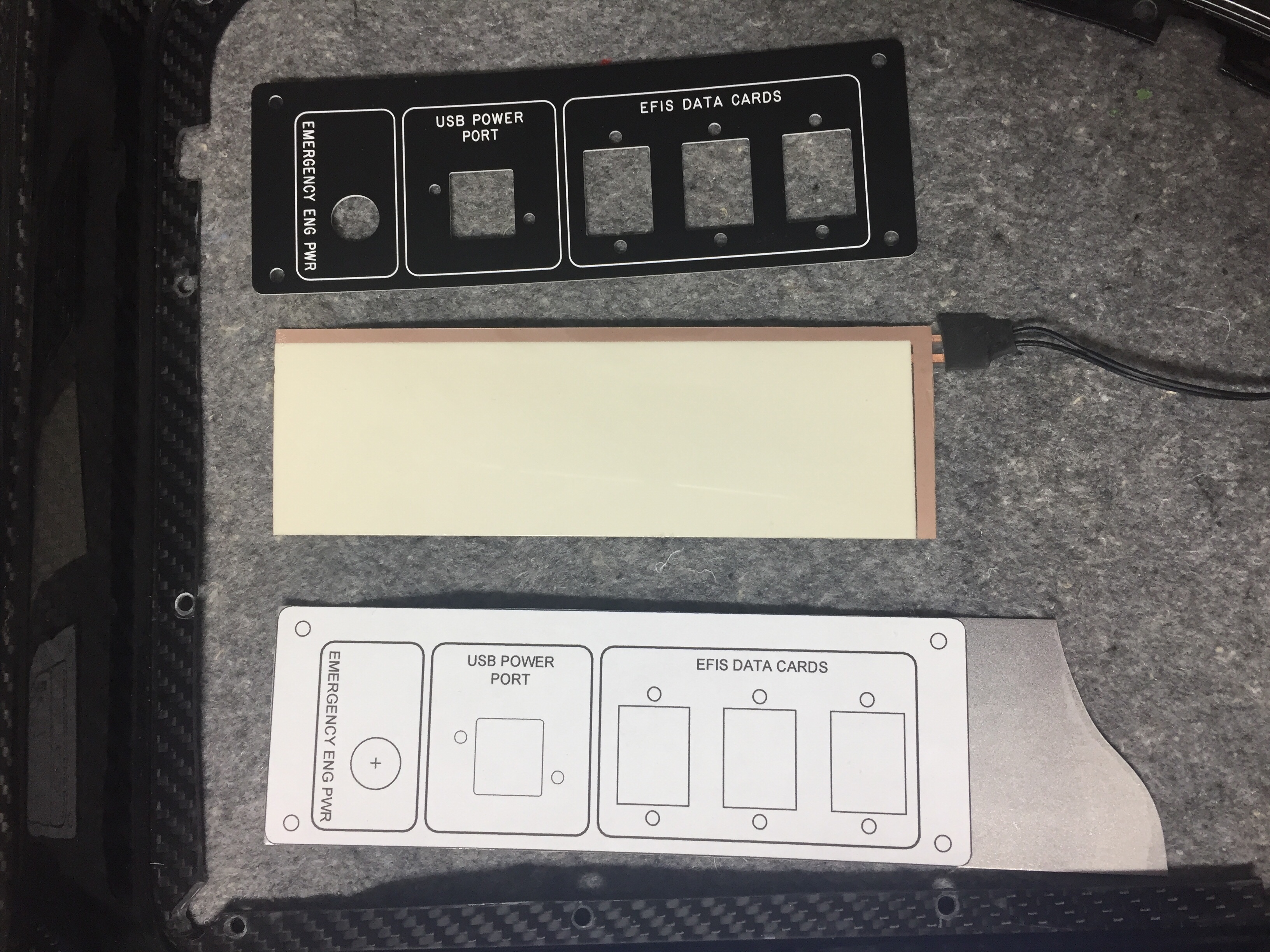
I also hooked up the lower console panel back lighting just to see how it works but won’t get the rest of the components connected until after power is applied.  That is the next big step, so stay tuned!

More wiring plus some more wiring then more wiring

Wiring continues as I think I’m nearing the end only to discover more runs that need to be installed.  I reworked the nutplates for the back up battery on the subpanel and have the subpanel back on the fuselage temporarily to continue bundling wire runs.  The amount of wire I hadn’t thought of is a little higher than I was expecting, as I thought I had a good handle on the “pre-work” for the avionics.  Rudder trim board, a few relays, the lighting control module, and a few others all popped up as I put components in place.  I’m working hard to keep the runs neat and tidy as I go.  I’ll ziptie everything in place once I feel that I’m done with wiring but I’m sure I’ll forget one or two and need to redo the zipties.

I had to have one of my panel overlays re-etched since I decided to add an emergency power switch for the engine bus.  I had originally designed a two relay system that would automatically provide backup power directly from the battery to the engine fuse block (bus) should the main power supply fail (master contactor, etc.).  A three position switch would be off, armed, and test allowing the system to be tested before flight.  I decided it was too complicated and didn’t design the panel or schematic for it, but now regret that.  Essentially, it is only redundant for the master contactor, but now that I’m visually seeing the path of power all going through the contactor as a single point of failure, I want a backup.  So I’m running a DPDT 40 amp relay from the battery to the engine buss.  I had considered a diode which would isolate a short in the main system but decided to not plan for multiple modes of failure.  The switch will be red guarded and the second pole will have be an input for EFIS annunciation to verify the relay’s activation.

I also forgot about the control stick wiring, which is the last connector needed for the ACM to be fully plugged in.  I don’t want to fit my control sticks until I rig the surfaces, as the throw of the stick as is now is greater than when properly rigged.  So I pulled wires, labeled them, and terminated them on the ACM side.  This is when I realized I went a bit overboard on the number of switches on the sticks.  I had planned on the typical Coolie hat trim switch, PTT, AP disconnect along with a TOGA, rudder trim toggle (horizontal orientation), and possibly a IDENT or comm swap.  It’s a lot, I know.  The Tosten grips have all that but I found out that I can’t use all of them!  The AFS/IFD setup doesn’t have an input for a TOGA as discovered after a lot of research and question asking.  The AP simply auto sequences the MAP based on the flight plan so no need for a TOGA.  The downside is not being able to go missed earlier than the MAP while on AP, something I’m used to in the Diamond with the G1000.  Not the end of the world.  I decided against a IDENT and comm swap switch as I just think they are not needed since I have to touch the panel anyway and I mean seriously, am I that lazy??  Ha, yes I am, but those two features still didn’t make the cut.  So, I wound up with three axis trim, PTT, and AP disconnect (AFS calls this CWS which it’s not but whatever).  A TOGA is reserved as a coming feature from AFS.

The GPU receptacle is also wired up now in its hidden location under the copilot’s seat.  I wired the GPU contactor such that it will power the full system but not charge the battery, as the Shorai will have it’s own balanced lead to connect the dedicated charger on the ground if needed.  Because I’m electron dependent, I will never jump a dead battery and take off, so no need for external access.  The GPU will be in the hangar for maintenance and/or learning the avionics.  I cut a little flap in the seat foot well wall and mounted the receptacle to the seat rail support.  It worked great and will have one bolt on the seat bottom to help secure once that area is all complete.

The big wires were taking up a lot of room on the shelf and with the components on the firewall all mounted, I could get the thick stuff installed.  I took some time to determine what size lug would be needed at each end of wire and ordered all the supplies in.  Great move because I had all I needed plus a few spares of everything.  The crimper I bought from Amazon worked well and it was a pretty easy, fun job overall.  It helps me visualize the power system now even better and I’m happy to say that I feel safe and secure with the architecture providing power for the plane.

After receiving the newly etched panel, I could fabricate the last of the switch panels so the avionics would be ready for final install.  Just like all the others, I started with a printed 1:1 image of the panel I had designed spray glued onto the aluminum sheet.  I cut that out then final trimmed it using the acrylic overlay before painting it black.  The back light panel is placed on the aluminum panel and positioned using the overlay to get it just right before trimming for the switch and USB ports.  This one was pretty easy with large cut outs.  I use 3M double sided tape to secure the back light panel then lay the adhesive backed overlay on top to finish it all out.  I use a Sharpie to color the white on the edges of the overlay to help control bleeding from the back light and give it a nice finished look.  I did have a little trouble with the wires on this panel and wound up replacing it all together with 22 AWG Tefzel soldered on the panel itself.  I wish I had done that with all the others, as the wire used from the panel is crappy and hard to terminate using the micro-molex connectors.  It turned out great, though, and is the last piece of the instrument panel.

Finally, I worked up two brackets for the micro switches on the doors and wired those along with the one on the baggage door for the lighting control module.  I also used the micro switch on the baggage door as the safety switch input for the EFIS annunciation.  More wires to run, oh boy.  A pretty quick job that should work just fine.  I did have to run an additional wire up to the overhead as I had picked up power and ground for the door lights from the overhead lights and that’s not how the lighting control module is set up.

While my plane does have a lot of wiring, it’s nothing compared to the big boys at work.  This shot is behind the port side avionics bay in the C-17.  Now that is a lot of wires!

Shutting the door on the doors!

Doing things better the second time seems to be a driving motto for my project.  The paint on the overhead console is a great example.  With it properly prepped, I sprayed primer on it using the adhesion promoter and instantly saw improvement.  Once the primer cured, I did some test scrapes and the stuff stuck like epoxy!  After that, the color was easy, again using adhesion promoter after a good wipe down with tac free.  I followed all of that up with two coats of the satin clear on the entire painted interior.  It’s about time I replace the cartridges on my respirator.

I also fixed the rear foot well spar paint after cleaning the old stuff off and re-scuffing and priming the surface.  I wound up test fitting a few pieces of the carpet just to get an idea of how much metal is exposed and what actually needs to be painted.  The Aerosport carpet is nice, I couldn’t have done a better job myself, but they aren’t an exact fit which is a bit irritating especially for how much it costs.  Not sure if all of the patterns are like that, but the floor carpet for the rear foot well is about 1/2″ too big on length and width, so one side or both will need to curl up a bit.  Never noticeable once it’s flying, just being picky I guess.

The doors are finally done!!!!  The last coat of color and clear went on smoothly and I’m calling them fully baked.  What a royal pain in the ass they were.  I am very happy with how they turned out, though.  I put the Aerosport handle covers on and got the Plane Around center cam final installed with the roll pin.  The door lights went in for good as well. I took my time putting the final door seal on from McMaster Carr and made the seam hidden by the strut and strut bracket.  I used a bit of E6000 glue to ensure no gap in the seal lets water in up there.  Holding my breath, I closed the door and much to my surprise, both closed with the seal on smoothly!  The right side door is a bit more firm on the handle motion, but the wife is happy with it which is all that matters.

Now that the paint is all complete on the inside, I was ready to install the front windows.  Repeating the process from the rears, the right window went in very smoothly and thanks to good prep work and patience, the inside finish is nearly perfect.  I wound up with a very nice fillet of adhesive creating a nice finish around the perimeter of the door cutout transitioning to the window.  I did notice that the strut now feels much better with the extra weight and doesn’t cause the door to fly open violently.  If anything, it needs a bit of encouragement to go all the way up but has no problem keeping the door open once it’s there.

It took one more evening of work to get the left window in which again went very smoothly.  One additional piece of prep was to put masking tape on the outside of both front windows to help clean excess adhesive from the gap.  It will just make paint prep a bit easier and quicker.  Again, that gap gets filled in with more adhesive after paint for a flush clean look and finish.

I’m back to cleaning up the inside, yet again, of dust and debris since the windows are now in and I can control what goes into the cabin.  The seat belts and receptacles were bolted back in and I riveted on the baggage door panel and gas strut (which I keep forgetting is on when the damn door hits me in the stomach).  Avionics are shipping soon so I need to get the wing root wiring harness complete to be ready to put the expensive boxes in next.

Nope, doors still aren’t done

Have I mentioned doors suck?  Next airplane I build will be open cockpit.  I pressed on with fixing the outside gap and leveling the doors with the cabin top.  As I did with the pilot side, I used the door itself on the copilot side to create a mold in wet epoxy and then trimmed to a rough shape while still setting up.  What a neat trick, thanks Kurt!  Sand, fill, repeat.  Woof, I’m tired of this and very happy I didn’t build a Velocity composite airplane!

Finally, I got to a point where the door gap was consistent and had a proper gap so time to move onto fairing the doors to the top.  A few spots on the frame were lower than the door which resulted in a uneven profile.  This is where the SuperFil is really nice, as it goes on smoothly, is lightweight but strong, and sands wonderfully.  The key is to be patient and not make it perfect with the applicator.  I’m bad at that and wind up causing more work for myself down the road.  Either way, its more sand, fill, repeat to get a good profile around the doors.  I found the pilot side to be a bit worse than the copilots on the aft edge, but better on the forward edge.  On the bottom of the doors where it meets the aluminum structure, I sanded the door face down to smooth the transition, as it didn’t need much.  I figured that would be better than trying to put a few layers of filler on the aluminum.  I’m quite pleased with the way that turned out and it was an easier job.  Meanwhile I continued to perfect the jams, filling and sanding little spots that I saw or felt.

With the process of using the doors as molds, combined with the earlier paint issue near the door strut, I needed to touch up some paint spots again.  I took advantage of the need to fix a crack that had already developed on the left side aft hinge cover.  This was from me twisting the door inadvertently while working on the pins.  I used a Dremel to dig down to the joint between the wood and glass and filled with 5 minute epoxy then filler.  Now, that would have been a quick fix except that I doubled my work load by closing the copilot door on the air hose causing the same issue on the aft pin on that door too!  But wait!  Call now, and I’ll screw it up even further for only shipping and handling!  I later went on to shove the fuselage back into the garage after a final (ha, no not final) cleaning with the doors open.  Guess what doesn’t fit in the garage with the doors open?  Yup, twisted the door really good (glad it didn’t rip it off the hinges) and cracked another one.  Seeing a trend?

So three fixes later, plus a little TLC on the door edges, and they are ready for paint again, this time hopefully for good.  The outside of the door jams are also finally done and satisfactory to my standards.  This took a ton of time overall and was just as much work as I thought they’d be.  I could do it better and faster next time, but I doubt there will be a next time for me!  I rounded over the hard edge which will help the final paint on both the doors and the cabin top.  I wound up with a 2-3 mm gap all around and it’s close enough to the naked eye that it looks really nice.  I spent some time reinstalling the pin guides and really have the handles and pins dialed in for smooth operation.  I tested the seal temporarily on both doors and you don’t even realize it’s there now, which is perfect.

I took the chance to put a tape of glass over the seam between the top and the aluminum followed by two coats of fill to smooth the transition.  This will make a nice finish under paint down the road and is completely cosmetic, not structural.

The only Aerosport product left in the storage rack were the headliner panels, so I got those down and knocked off all of the dust.  They are a very thin layup of fiberglass that the headliner material will adhere to and then velcroed to the cabin top.  I needed to get them trimmed and fitted before putting in the windows, so spent a few hours on each getting just the right shape and fit.  It’s not hard, but it was a bit tedious as there isn’t a good way to get a pattern since each area and side is a bit different.  Lots of fitting, removing, trimming, repeat.  In the end, they fit very well and I’m excited to have them finish out the interior of what will be a very nice and comfortable cabin, no doubt.

I ordered two different color headliner material (available a lot cheaper from online retailers than Aerosport) and found one that matches very closely to the grey of the interior.  I’ll cover the panels down the road when I am between major projects.  The carpet from Aerosport came in and looks great in the bonus room upstairs.  This leaves a bit of paint left to complete the inside work.

The cart before the horse

Finishing the interior now consists of painting the remaining surfaces not covered by the Aerosport panels and painting the panels themselves.  The doors, door frames, and a few other areas needed the Presido gray applied and I wanted to get that complete so I could turn full focus onto the outside.  I took my time to prep the areas needing painting with paper and tape and then set to work ruining my index finger with four cans of spray paint.  I used the SEM sand free to wipe all the surfaces down after a good cleaning with a wet rag to get rid of dust.  I then primed a few spots that had the bare filler / metal exposed.  I then put three coats of color on it, letting it flash in between coats.  Finally it was two coats of clear on the doors and door sills.

I was excited to put the recently anodized hardware back on the doors to get the struts mounted for good.  The anodizing came out really nicely.  I had a few “trinkets and trash” done but the main parts were the seat belt brackets that I needed complete so the seats can be sent off for covering.  While installing the bolt holding the strut to the brackets, I managed to scrape off some of the newly applied paint.  I then proceeded to scream at the top of my lungs, collapse on the floor in a heap of fiberglass dust, and cried like a little school boy.

After that, I picked myself up and started asking questions.  SEM is advertised as a flexible dye, not a spray paint, for plastics, vinyl, and leather.  I know others had used it on their interior with good results so I was pretty confused.  I do have some spots on my carbon fiber overhead that have flaked off, but I attributed those to poor prep on my part, mainly not enough scuffing for it to properly adhere.  After a few dire nights thinking the entire interior may need to be stripped, I called their tech support and got reassured that the Color Coat is adequate for all substrates.  They did say it’s not going to be as durable as a two state professional coating, but it should be just fine and touch ups will be easy.  Sure enough, the areas I saw flaking was poor application on my part.  I tried pretty hard to scuff and scrape over an area I know I applied it correctly and the finish help up very well.

The need for a few touch ups is just as well, because I but the cart before the horse on painting and still needing to sand.  The external door gap was the next hurdle to tackle and I knew I really made a mess of it when fitting the doors originally.  While I used the cleco to cabin top method, I originally started with the plans directed 45 degree bevel before turning to square the door edges off so paint will stick better.  That left me with a large and unsightly gap between the cabin top and door edge seen from the outside.

Thinking smarter but not harder, I decided to put globs of filler on the top and then prep the doors to simply close and latch, creating a nice even gap all around.  I had seen others do this with layers of tape.  Now where they got that mystery tape, I don’t know.  I can’t find any tape thicker than about 20 mils and it’d take 200 feet and 10 layers to create a nice 2mm gap around the door edges.  So, I compromised and kept the globbing plan but simply wrapped the door with brown packing tape and shut it.  I then monitored the epoxy flox mix during curing to start working it as it hardened.  I just used razor blades to go back and cut by hand an even gap in the curing epoxy.  It was really easy and very clean.  The trick is to catch it at the right time.

I cleaned up the tape residue and a few areas of the flox and was really happy with the results.  It was a good base for poly fill to smooth everything out nicely.  It’s also a lot stronger than just the poly fill.  I rough sanded the epoxy to get an even more consistent gap and then put the first coat of poly fill on to dress it up.  Another sanding, this time with a lot of fine tuning pretty much finished it up.  A few spots have some pinholes or voids that will be filled in after an initial prime coat is applied to highlight any last defects.  It wasn’t nearly as much work as I thought it’d be and I’m happy with the outcome.  Now, on to the co-pilot’s door!

It’s not easy being pretty

I realized I forgot a post about installing the door seals after building up the door frame lip.  As always, it took more effort and involved more frustration than I had originally imagined.  To sum it up, my problem was not having a consistent gap between the door frame lip and the interior of the door.  I had some tight spots and some just right spots.  The issue are the tight spots that take a lot more force to squeeze the door seal bulb than you want to put on the door.  Basically, I had to start again with fitting once I got the seals.

My first idea to make the seal fit with less squish was to remove a lip on the u channel of the seal.  It’s designed to help hold the seal onto the door frame lip but it also added about 1/8″ of bulk.  While that did help, it wasn’t enough.  I tried different combinations of seals, but due to the uneven gaps, the smaller seal wouldn’t actually touch both surfaces in a few spots and adding filler would have required re-sanding and contouring the inside.  That wasn’t a viable option, so it was back out with the angle grinder and Scotchbrite pads to go to town on the door frame lip.

I was shocked at how much had to come off in some areas.  I determined this using a marker and template, acting as a scribe to measure the proper gap.  I used an area that had a nice amount of squish on the seal but not too much as a gauge for the entire door gap.  It worked well and after making a lot of dust all over the just cleaned interior, I was getting a nice fit on the door seals.  I know I’d have to add some filler on the door jams anyway to get them looking nice, I wasn’t too concerned about my grinding methods.  I mainly wanted a good fit, cosmetics will come later.

After a few evenings and a lot of opening and closing the doors, I had achieved a good consistent gap for the seal and was happy with the fit and function of the door seal.  I noticed that even after two nights of the door remaining closed, the seal was already getting broken in, making it easier to close the door.  Folks say these seals need to be replaced as they wear down, so it will be a maintenance item every other year or two,, I’m sure.  What I wasn’t happy with were the pins that held the doors shut.  The Plane Around latch was doing its job of pulling the door closed, but the back pin still needed to do some work to align to the block.  The pins I have are stainless with epoxied magnets in their tips and are shaped like bullets.  That sounds great if the doors are almost perfectly aligned, but they did a poor job of any movement into the aluminum blocks that I also had.  Even after a few weeks of working, the blocks were gouged and the bullets were wearing scars.

Luckily, a call to Sean at Plane Around solved my problem.  He had a set of angled stainless pins, much like the shape of the stock pins, that were hollow for a magnet to be dropped into.  These use setscrews to attach to the rods and can be positioned to most efficiently capture the blocks and align the pins.  He also has Delrin blocks that are machined to have a nice rounded funnel shape.  The stainless glides effortlessly on the Delrin making the closing and opening of the door handle a seamless effort compared to the rough metal on metal that I had.

It took some time to fit, because I had to cut the rods and machine the pins to orient them just right but the effort was worth it.  My doors now close perfectly with the seals and have a firm but easy motion in the handle.  I fine tuned the blocks’ alignment with shims which allows the pins to insert perpendicular to the block, reducing the friction along the way.  This has been a huge burden lifted, because while the doors were functional and airworthy, they weren’t easy or pretty.  Now they’ll be both.

Dirty Door Details

I want a really finished looking product for the doors which requires covering / filling in a few key spots such as the pin guides, hinges, and install holes for the gear rack and center cam.  Some have laid fiberglass over these areas, others have left them open, and a few folks are using basswood to create cover plates.  Since I’m better at the wood and had some on the shelf, that’s what I chose to do.  The pin guides I just roughed up and applied flox directly on them, roughing the shape in to match the door lines.  I used some scrap pin material to keep the hole clean.


I used the basswood to fill in a hole used to install the center latch and create covers for the hinges.  It was pretty easy to trim and shape the wood for the plates needed and after I coated all sides with epoxy to harden the wood, I epoxied the plates in place.  I then went back with Superfil and did the final contouring and shaping to match all of the door’s surface.  I’m really happy with how it came out and while it was a bit of extra work, I think it’s worth it in the end to not look at exposed hardware.  I’ll be covering the hinges on the cabin top down the road as well.  Finally, I took some time to fill in little surface blemishes and final shapped the interior edge of the window frame.


After all the sanding was done and I was happy with the doors, I wanted to re-mount them for the final time.  Here is where I realized I screwed up.  The hinges are mounted to the cabin top with the hardware essentially epoxied in (see prior post) so I had to slip the door onto the hinges and install the hardware behind the new cover plate I had spent all that time creating.  Bad idea.  It’s impossible to get the washer and nut on each screw on the door side of the hinge.  My fingers are fat and not triple jointed so I spent an hour raising my blood pressure far beyond healthy limits struggling with it.  I decided to walk away, burn the project to the ground, and start over.  Okay, really, I just took the rest of the night off.  The next evening with a calmer approach, I fabed up a handy little tool to hold the washer and nut in the cavity while I installed the screw.  I used some basswood and some aluminum to create a captive wrench so to speak that worked beautifully.  Had both doors installed in about 20 minutes.  Wish I had put the hinges on the door then bolted them onto the fuselage, but oh well.  I installed the last plates to close out the hinge area and applied filler to smooth is all over.  This completely closes out the hinge cavity on the door not only making it look better but allowing the door seal to work properly.


Meanwhile, I set about working on the instrument panel and center console.  The big Aerosport order had arrived a few weeks prior and I was eager to play with all of the cool stuff.  I started with the instrument panel and got the backing plate and the panel itself fitted in their place.  The side skirts on the tunnel attach to the lower instrument panel with the center console mating up to it.  This stuff is top notch quality and is going to be really awesome filled with fancy avionics!  I took my time to fit it all and used nutplates to ease future maintenance and removal.  I chose to countersink the carbon which left it a little thin and brittle, so I coated each screw hole with light epoxy to help strengthen the area.  I also cut out the main areas which will have the metal inserts leaving a 1” flange to be trimmed to final size later.  The center console was positioned and I used a strap duplicator to drill the holes matching the tunnel.


Since my plans include using the ACM from AFS, I want to use a fancy push to start button but couldn’t really find one that I liked.  The Honda S2000 button others have used are hard to find these days so after a few returned orders, a deep Google search turned up exactly what I was looking for.  It’s a simple Apem NO switch that has a LED light actuator.  It’s also the right size to be proportional to the panel location.  I couldn’t help but to drill the hole and mount it up to see how it looked.


The Andair fuel valve is mounted through the tunnel on the center console as well, so I set about locating the screw holes.  I mocked up the valve itself on the stock mount and will need to create a larger mounting plate for the valve housing down the road.  It allowed me to trim the handle extension and locate the plate on top of the console.  Again, had to mock it up and do some airplane noises while turning the valve.  The noises worked perfectly; so did the valve.


Finally, I cut the throttle quadrant area out and worked on installing the quadrant onto the tunnel cover.  Thanks to Ed and Aerosport’s awesome YouTube video, it was pretty painless and I wound up with a very nice fit with the throttles fitting flush with the console when everything is installed.  I cut a large slit on the throttle friction lock area that allows easy removal of the console.  I’ll create a trim plate to cover up the slit for a finished look.  With the main carbon work done, it was time to drop off the instrument panel parts and center console to a paint shop for a clear coat.  I want to leave the carbon look exposed but wasn’t happy with the finish right out of the mold.  I had originally asked Aerosport to clear the items but they quoted over $1500 just for the clear coat.  I almost choked.  I love them to death and they’ve done a lot to help, but I couldn’t swallow that pill.  A few calls around the area and a local custom motorcycle paint shop could perform the work in four days for $250.  We’ll see how they turn out next.

Hold the door, Hodor

Any big cut or drilling job comes with some anxiety and the door pin hole is no exception.  Now that the door handles and pins are all installed and working like a fine oiled machine, they need a home to rest in.  I removed the magnetic tipped pin inserts and used two ground down bolts threaded into the rods to locate the exact spot to drill into the door frame and fuselage bulkheads.   This worked really well as I was able to position the door flush with the fuselage and locate the drill placement without worrying about future misalignments.
I have some fancy aluminum pin guide/blocks from IFlyRV10 that go along with the magnetic pin inserts.  These help guide the pins in and just make closing the door that much easier and smoother in coordination with the PlaneAround center cam.  I polished the holes with some light sandpaper to get a smooth action and am really stoked to say all four holes are in the perfect position the first time!
The next project is to prep for the door seal.  As most have done prior, I am going with an aftermarket seal that affixes to the door frame rather than the door itself.  Since the frame isn’t designed for it, a little prep work is required.  I needed to build back material for the seal to mount on that will put the bulb nicely against the door.  I purchased twice as much seal as needed so I could use half of it sacrificially to form the new lip.  I mixed up a big batch of epoxy and flox and used a baggy to fill the seal.  Then I took my time to press on just enough to hold onto the frame.  Once dried, I pulled the seal off which left a nice new structure all around the door opening.
With the door on, I marked the areas that needed to be sanded down or built up a bit with filler to get a nice consistant gap all along the door lip.  Despite all the dust, it was a pretty easy task and soon enough I was ready to put on filler to smooth things out.  I did both the inside and outside.  I’m a little bummed that I’ll have to re-shoot some paint on the inside, but I can mask of the overhead console so that will make it a bit easier to blend.
Meanwhile I built a bed up of epoxy and flox on the hinge mounts since a few of the washers and nuts didn’t sit flush with the cabin top due to the contour of the inside surface.  This allows the torque to be spread properly over the newly built up area.  I let the epoxy cure about 75% then put the washer and nut on so it compressed the fill into place.  After it cured I finally torqued them to spec.
A few evenings of sanding and filling later, the left door frame is ready for paint on the inside and the seal to be installed.  The right door is coming along with initial sanding and filling happening now.  Once the windows are in, I’ll fill the final door gap and finish the rest of the door frames.

Rack ‘em and stack ‘em

I needed to get the door pins installed so that I could lock the doors in their proper location to get the final trimming done.  It’s a cart before the horse thing, as it’d be nice to get all the trimming done but you need the pins first.  But to get the pins, you need to trim the doors.  Lot’s of half finished steps to complete the other steps here.

I’m using several aftermarket modifications as well.  The PlaneAround center latch is a no-brainer for its functionality and safety aspects.  It provides a cam in the center of the door to help close the door and ensures both front and rear pins engage the fuselage to keep the door closed.  It also basically makes it impossible to close the door with only one pin engaged.  The danger is potentially life ending, as several accidents have been caused by doors opening and separating from the airfarme.  Nothing to joke about here, you have to do this right and know the severity of the impacts.

I’m also using the low profile handles from Aerosport which are very nicely built and are a bit more high class than the standard Van’s handles.  With that being said, it means following three sets of directions that all leave a bit to the imagination.  Of course, I don’t read directions well so I started off by cutting my door racks according to the stock plans, not in half as I should have.  That looked like an expensive mistake, but VAF came through and I got a new set for the cost of shipping thanks to a very helpful fellow builder.

The door rack and gear system is simple once it’s all put together but is a bit challenging in assembly.  I was able to work through the plans, however, and soon had all of the parts cut, created, and cued for final assembly.  It all comes together very well in the end as long as you take time to ensure a smooth operation of the mechanism.  I’ll be filling in around the nylon blocks on the door’s edges so aren’t too concerned about looks here.

I also added cam locks to be able to lock the doors.  While they aren’t completely bullet proof, they will provide some security and deterence for people to not mess with the airplane or its contents.

Hey don’t forget

Tip for other builders.  Don’t forget to follow the steps that aren’t in the plans that you don’t know about but absolutely have to do in order even though nothing says to do them in order.  For example, the door strut bracket that attaches to the top of the cabin.  Yup, I forgot that.  I realized that in a moment of sheer panic and terror about 3 am one morning.

The strut bracket is a bit rudamentary from Van’s so I had ordered a very nicely CNCed version from Sean at PlaneAround.  Those have been sitting in my parts bin for two years now and despite all my hard work at the overhead console and finishing the interior of the cabin top, I forgot to install them.  It would have been a five minute job had I remembered.  It turned into a five hour job.

I would have to cut a hole in the overhead console and grind away part of the filler on the cabin top without screwing anything up to make this work.  Fortunately, I took my time and went at it very methodically.  I located the exact position it needed and drilled a few holes to start opening up the rectangle for it to slide in.  I got pretty luck and it proved to be a nice finished fit once all the filing and trimming was completed.

I then made up a jig to locate the screw holes since I couldn’t drill or mark from below due to interference of the console.  The jig allowed me to drill pilot holes from the outside and then enlarge to get the proper alighnment.  Worked like a charm and in no time the first bracket was screwed on.

As with everything, the second one goes quicker and easier so in one evening I corrected a big mistake with really nice results.  I doubt anyone could tell that they were installed out of sequence and looking back I wager it was even easier this way vs trying to sand and sculpt the filler around them while filling in the console.