This Bird is Squawking

I will document the biggest and most annoying things wrong with the airplane during the test flight here but do not plan on blogging about every repair or modification to the airplane. Mainly because I’d have to become a full time writer.

The flight tests went fairly smoothly and I finished the 40 hour phase 1 in under a month. Most of my issues were builder caused, I must admit. Either a rework or bad soldering, decision making or lack thereof, and a few “that’s good enoughs” that came back to haunt me were to blame.

I tracked these by creating a list in my phone/iPad that I could check off as I corrected the issues. The list kept growing for some time before it started getting checked off. It’s worked really well for me and actually motivates me to complete all the repairs or adjustments to get the check boxes checked. I can also make group entries into the logbook to keep track of the work.

I found that I had a lot of electrical gremlins throughout the first bit of flying. Solder sleeves are amazing little buggers that are notoriously difficult to use correctly. I used sparingly while building, but they still bit me a few times. The problem is you think the solder ring has melted completely but it hasn’t. The connection will be good until it’s subject to some vibration and then all kinds of weird things happen. My oil pressure spiked to 200 PSI, multiple random annunciations based on my discrete inputs, and a few others due to the solder sleeves. And I only have about 10 in the whole plane! I will use them now if I have good access to the connection, but if not, I’ve found using Dsub pins and heat shrink as more reliable.

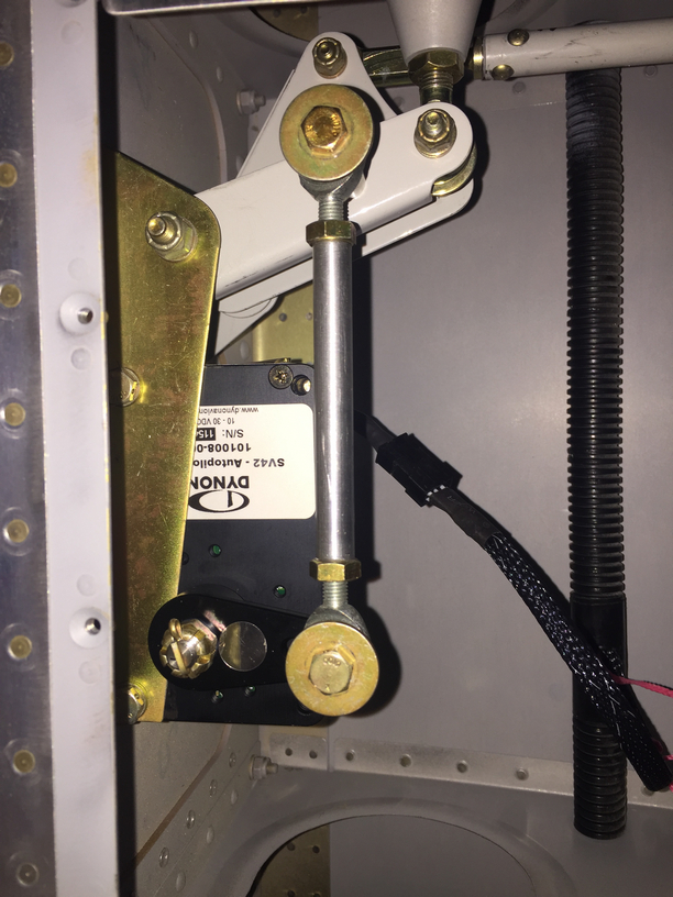
I had to reposition my EGT probes, as I realized they blocked 5 out of 6 spark plugs. I had a master cylinder bolt leaking just a bit. Lots more clamps and zip ties were installed, mostly firewall forward, to avoid chafing after a few oil changes and seeing where things moved a bit too much. I had to replace the autopilot pitch servo due to a service bulletin, roll servo due to slipage, and had to reinforce the rudder trim tab mount to get it to work effectively. I chose to rewire a few engine switches and add a engine master switch, which I should have done in the first place. That all neccessitated under the panel work, a new switch panel overlay and backlight sheet. The oxygen system leaked above 1200 psi (loose connection), and a few adjustments to the door light switches have been made.

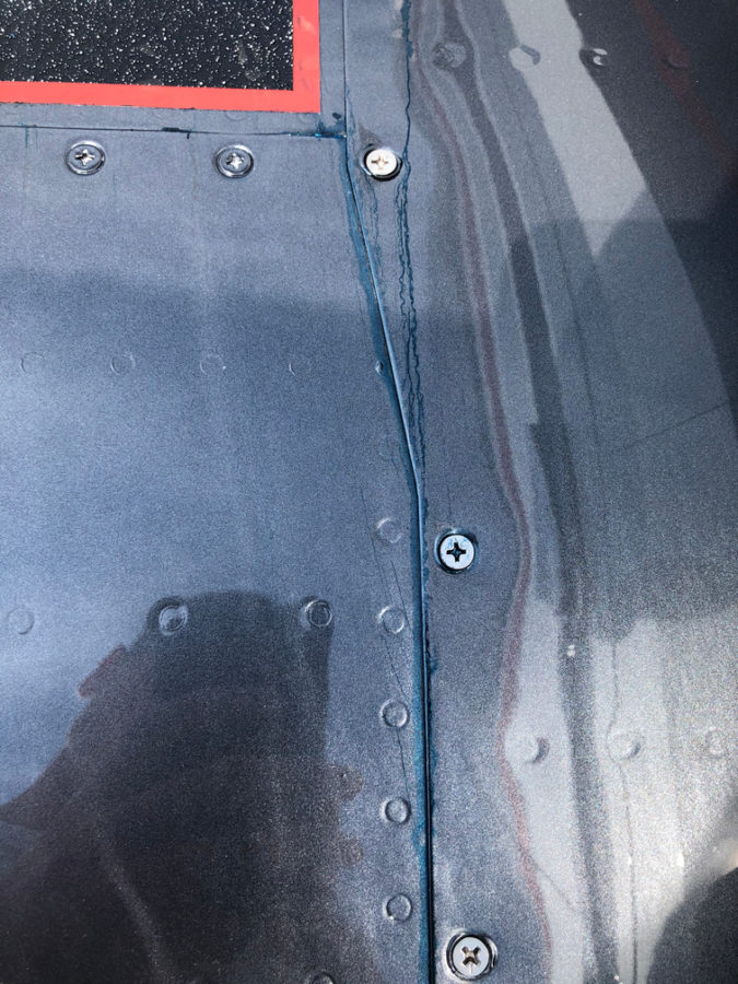
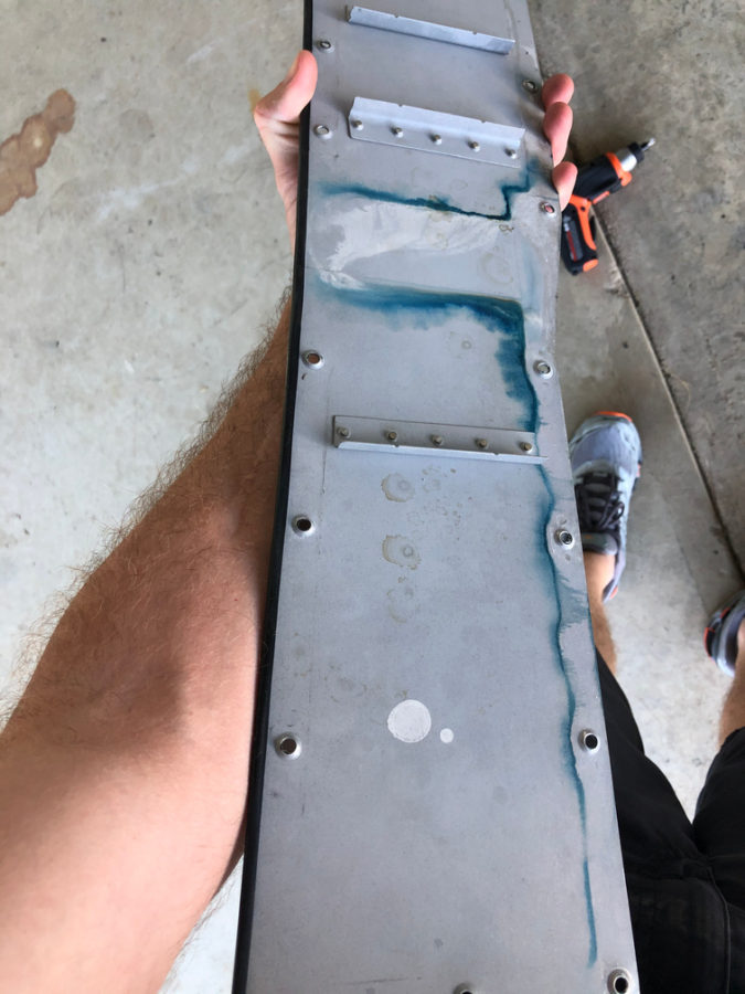
The biggest squawk is a leaking fuel tank. I am getting ahead of myself on the blog, but this was discovered post paint unfortunately. Turns out a little weeping rivet that I discovered prior to paint and thought I had fixed with the Loctite trick wasn’t fixed. In fact, it wasn’t a weeping rivet, but a pinhole in the sealant on the rear baffle. Fortunately, I spent an entire day and was able to use my borescope to provide a view and a coat hanger/tube of pro seal to apply sealant and fix the leak without taking the tank off. Not a fun job.

The engine ECU tweaks were pretty easy, although I’ve gone through four O2 sensors (leaded fuel doesn’t make them last long). I removed the air filters and just installed a mesh screen over the intakes. Speaking of intakes, one was too close to the exhaust header and a hole burned through it so that required a bit of glass work along with better heat insulation and a bit more clearance.

Lots of other tweaks and adjustments were made and most of these delayed discrepancies were taken care of during the first condition inspection performed in November last year. I do have a few more items to check off the list including new door hing covers, some finish rework on the interior windshield pillars, an intake plenum on the air conditioning condensor (more on that later), and adding a second tunnel access plate are all on the list for 2021.

Bottom line, you’re not done building when you’re done building. Flying brings on new stuff that you can’t forecast on the ground so it’s a continuous process to keep it in tip top shape. I also put some of this stuff off, as I wanted to get it flying so its been a challenge to get caught up after flying so much. I am now at a point where the regular maintenance time is decreasing vs the flight time increasing. The check boxes are all most all filled in!

Back to heavy metal work

One task that I want to document for others I forgot to mention is modifying the tunnel cover around the Control Approach rudder pedals.  The cable attach arms are relocated inside the tunnel so slots need to be cut for them to move freely in the cover.  I measured their arc and marked the tunnel cover where I wanted to split it into two pieces.  Before cutting, I marked and drilled a center plate to hold nut plates which will allow me to screw the two pieces back together.  It was a pretty simple modification as was cutting the slots for the arms in each piece.  Again, I’m trying to consider maintenance and access down the road as much as I can.

I also took the time to modify the seat rails since I got the Aerosport seat levers.  Others have described this mod and it makes removal of the seats a snap.  Step one is to remove the delrin guides from the seat bottoms and trim the first 1 ½” off followed by reinstalling them.  This allows the seat to be slide rearward on the rails and then tilted around the flap tube cover with the necessary clearance.  I then removed the aft rail stop and drilled through the rail into the plate below.  Installing nut plates below the plates lets you put bolts in place of the screw and nut on the stop.  Now, I can get to the bolts from the top down eliminating the need to reach under the seat plate to get the lock off, allowing the seat to slide freely rearward.  It all makes sense when you look at it.

I’m trying to knock out some little side tasks along the way now in the spare time.  I used some excess epoxy from a door filling session to install the front vent NACA scoops.  I drilled a few holes and used clecos to hold them in place while the flox cured overnight.  I don’t have proseal and didn’t want to use any silicone on the area since it will be painted.  With minimal flexing and a good scuffing on both surfaces, I am confident the epoxy will hold these just fine long term.  The scat tube will have a short run from there to the Aerosport vents that I installed in the instrument panel.

I also performed a quasi service bulletin from Sean at Plane Around.  When I received the lights from him for the overhead and doors, several had bad boards which he promptly replaced.  I got a call from him with an interesting finding.  He used a brass wire over a piece of foam to hold the LED boards inside the aluminum and plastic housing.  He found that in a few instances, the wire was touching the board and shorting out LEDs.  Awesome service!  He called and suggested using a different method such as silicone which is an easy solution.  I removed all of the installed lights and completed the rework after ensuring all LEDs checked good.  I took the opportunity to install the micro molex connectors on the remaining few assemblies as well.

Service bulletin complied with in accordance with published guidance, OPS check good!

And finally, another cleanup item to mention was the addition to the hangar family.  While she hasn’t been officially named, our new Best Tugs Alpha 2 arrived!  I ordered this at OSH last year to use on the DA-40 we fly now and for long term with the RV.  It cost a pretty chunk of change (plastic, let’s be honest) but man is it nice.  It will save my twice-operated on back for years to come and is really handy to maneuver the airplane around.  It took a bit of practice one afternoon but now it’s just like pushing a shopping cart!  I requested the smooth cover with the intention of having it painted by Jonathan to match the RV but didn’t realize the red anodizing was going to arrive.  Oh well, not the end of the world.

Staying in the lines

Throughout this progress, I’ve been finishing up the brake lines.  I ordered extra line for the run from the firewall to the gear legs and got them all fabricated.  The lines weren’t hard to make, but it was a bit tedious.  I am happy with the end result, however, and think that it will provide many years of great performance without having to worry about replacing tubes.  I do need to get some spiral line wrap to prevent chafing and that will allow the lines to be a bit better secured.  Mark Ciglia put his parking break valve in place of the firewall connections, which I’m mad I didn’t think about.  It makes it a bit cleaner and eliminates one extra set of lines, but oh well.  It’d cost more now to redo it.  Note to other builders!

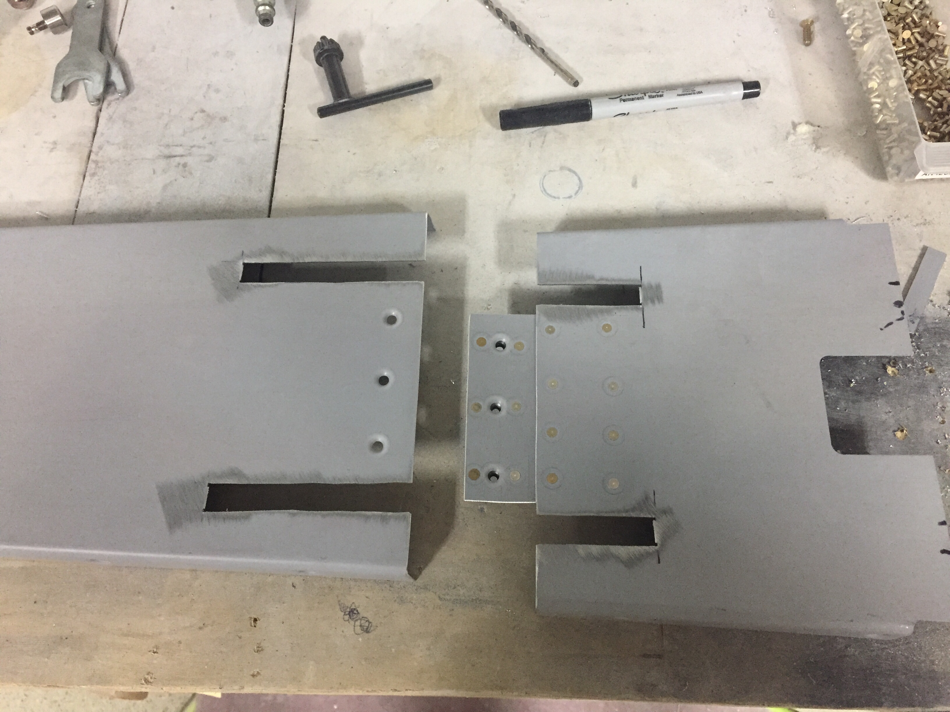
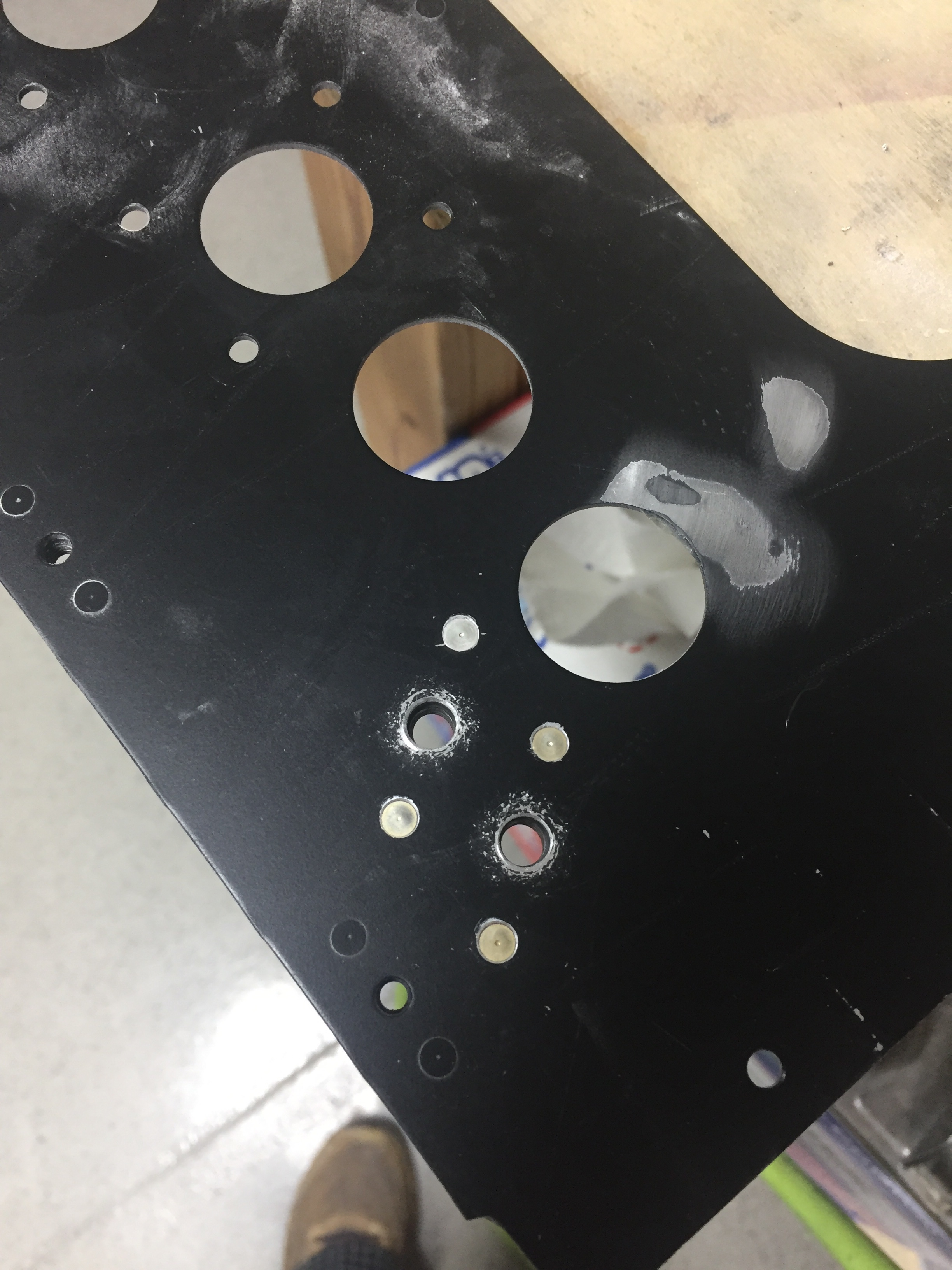
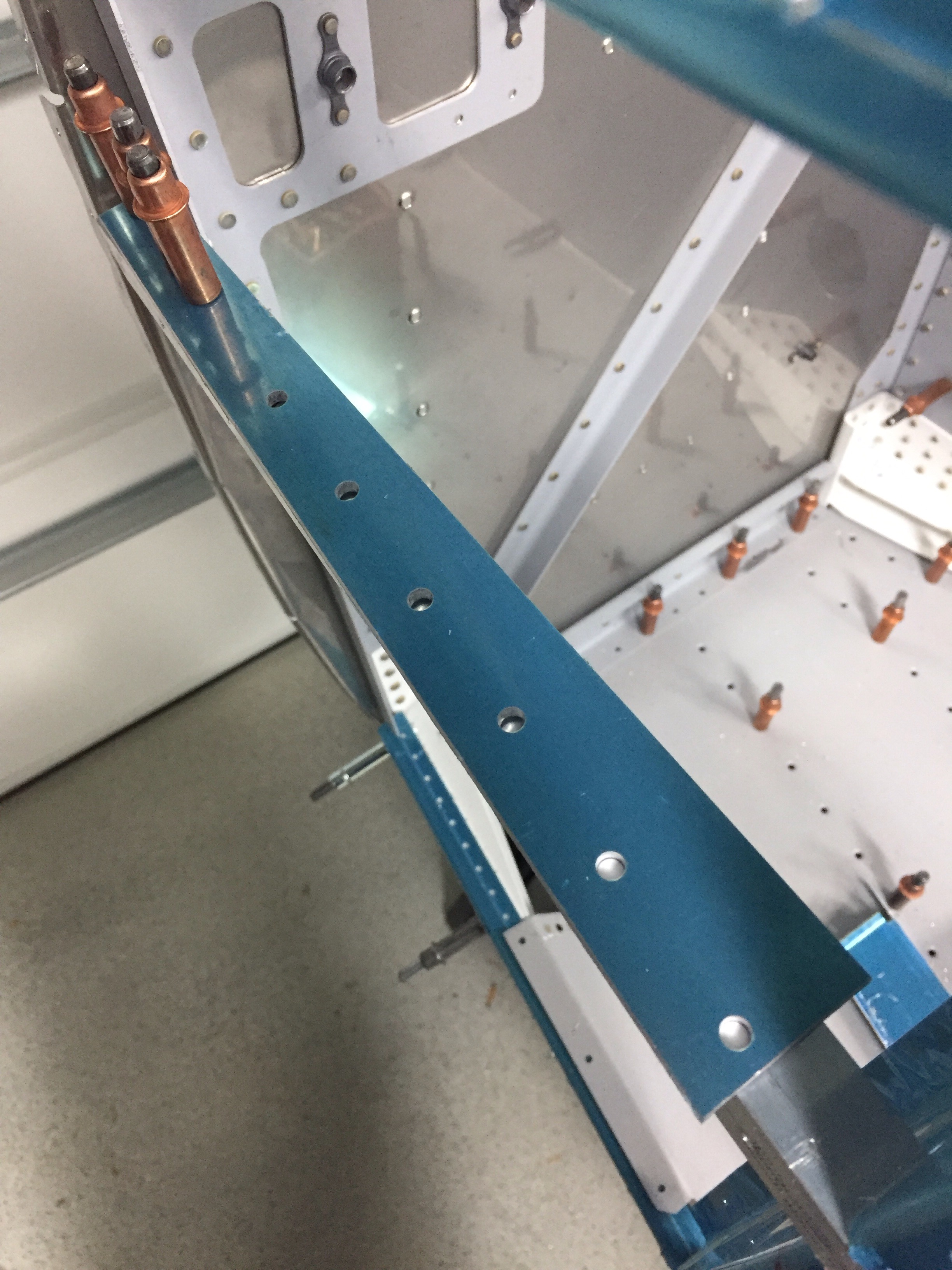
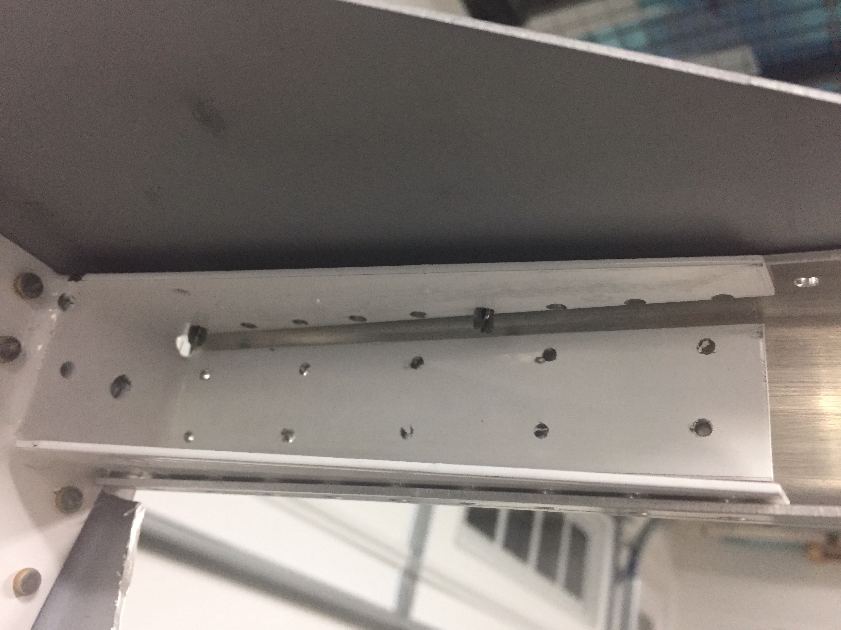
I also knocked out a few little projects, one being making new elevator trim bracket panels.  I had the beefed up fittings sitting in the parts bin and finally ordered the new access panels.  After countersinking and priming, the parts are ready to roll and comply with a SB from Van’s from many years ago.  This is a common upgrade and an easy one at that.

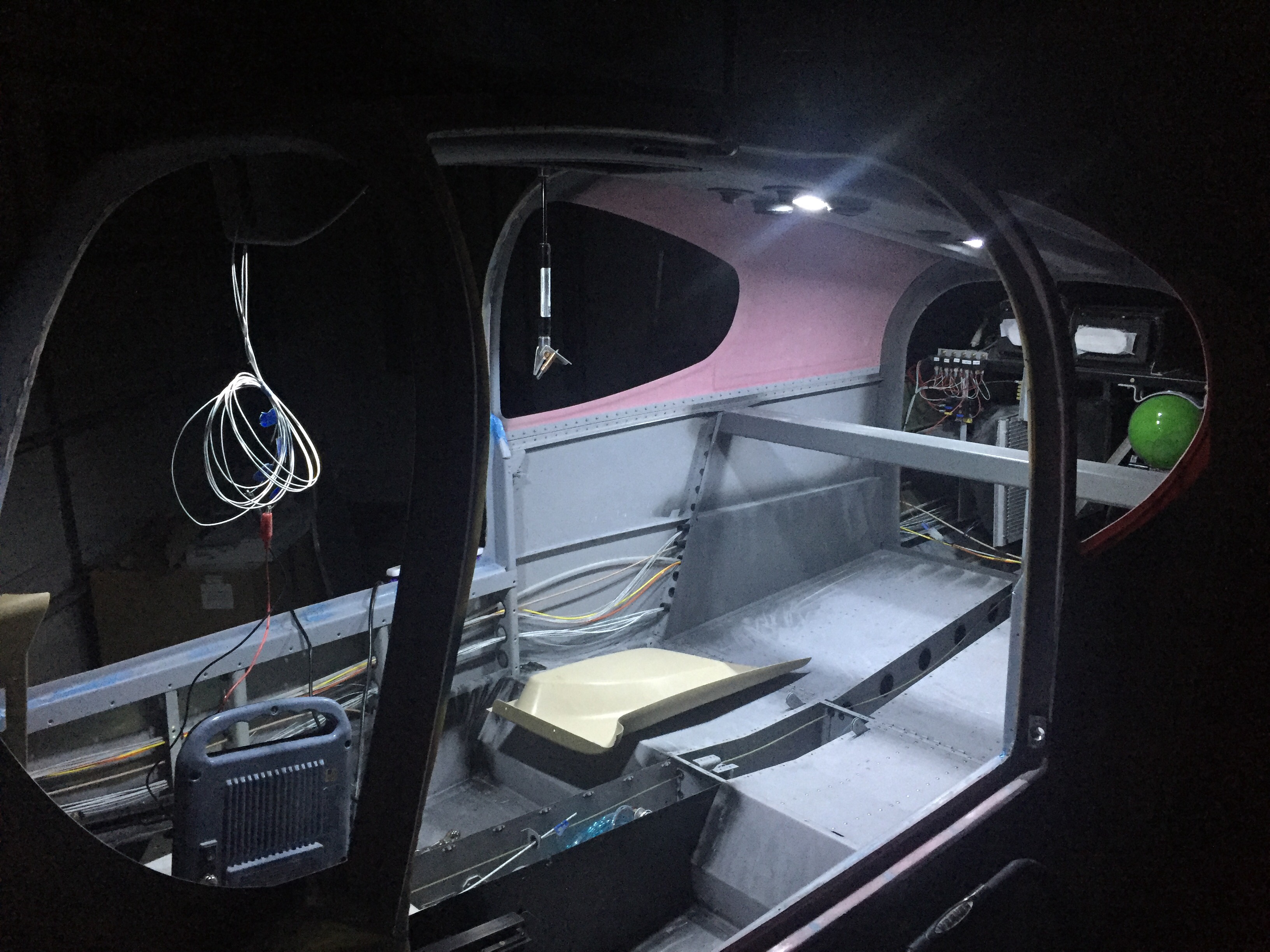
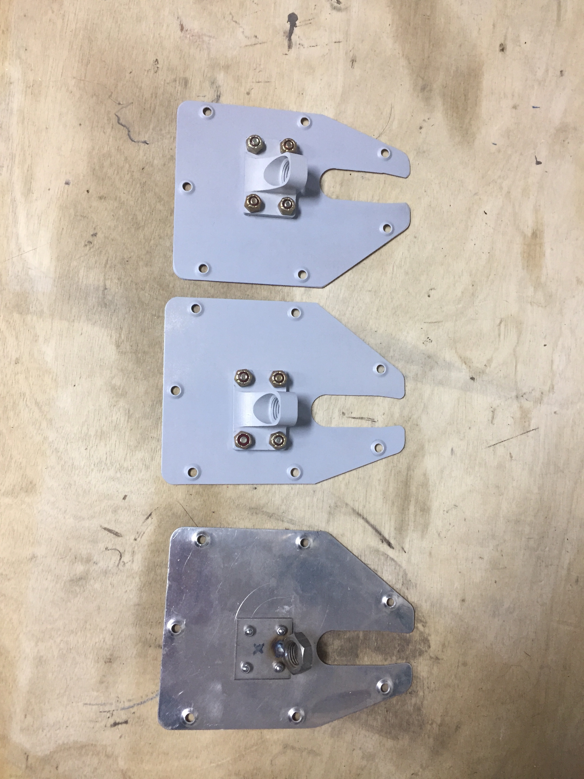
Another little project wasn’t so little.  I saved up a few tasks that needed to be completed inside the tail cone for one evening so I would only be crawling back there once (this time).  The first was to support the tail better.  I used two 1×4’s to bolt to the horizontal stabilizer mounts and put a caster on the bottom.  While the fuselage cradle has been great, the rear support isn’t far enough back to support my weight so far aft without something heavy like an engine hanging off the front.  So this was an easy fix and doesn’t take any room up in the shop.  It’s still very easy to roll around and reposition as needed.

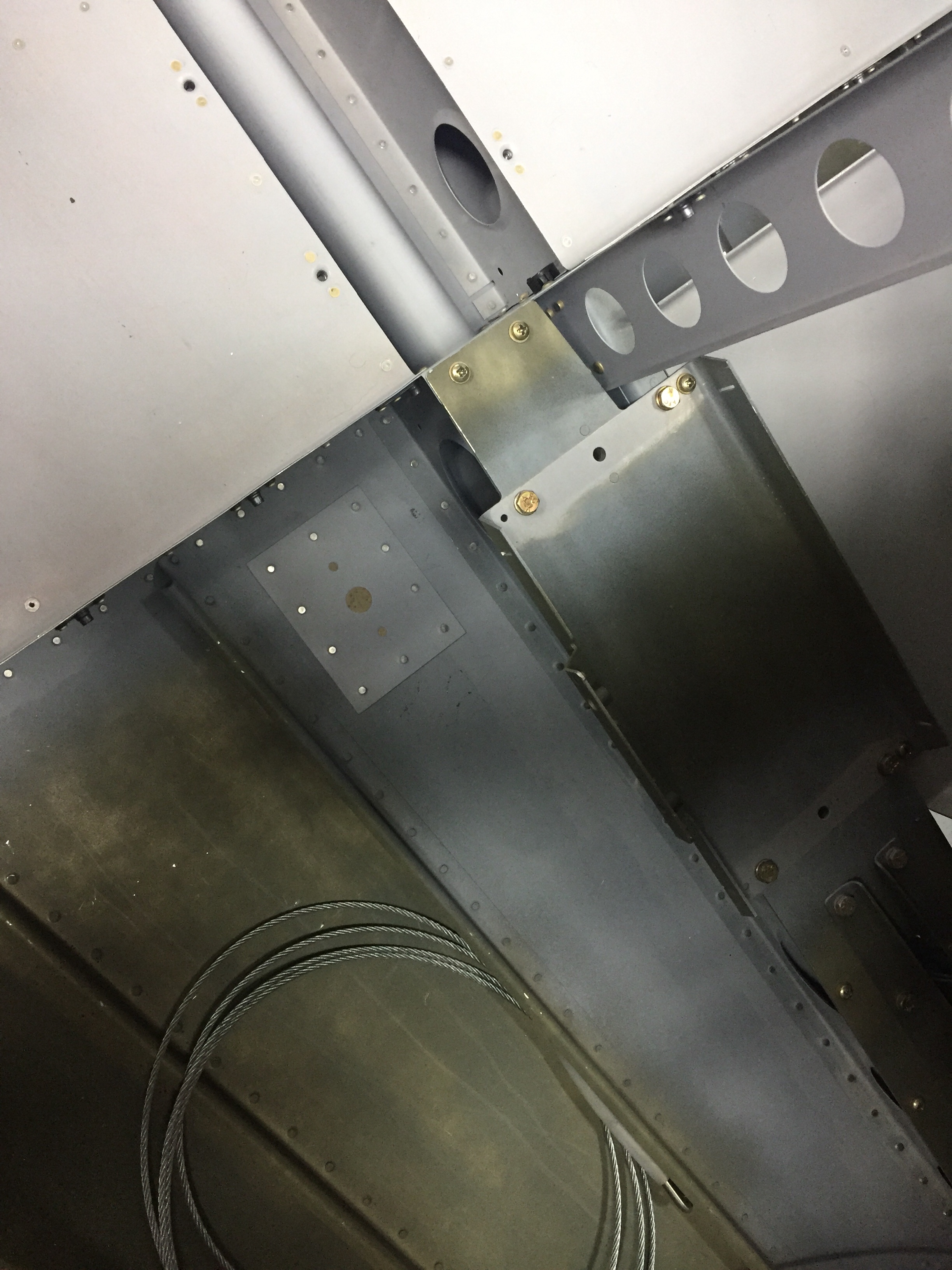
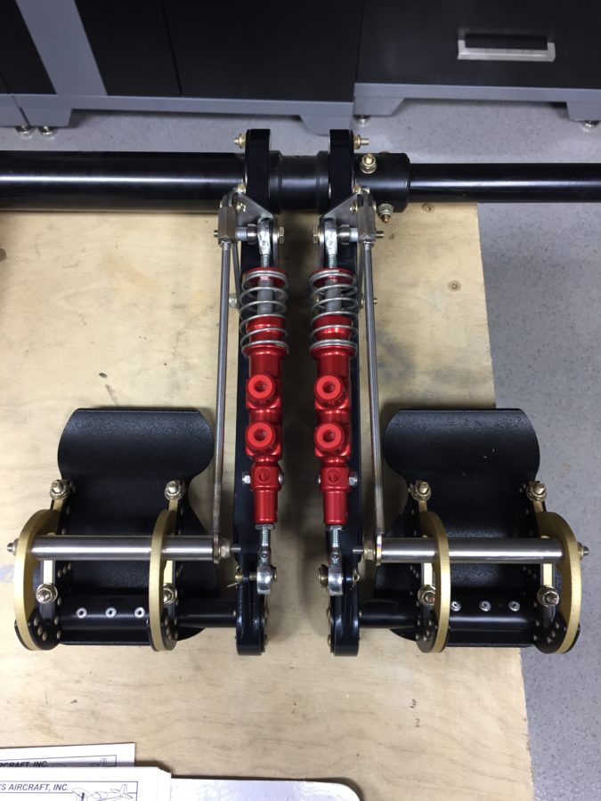
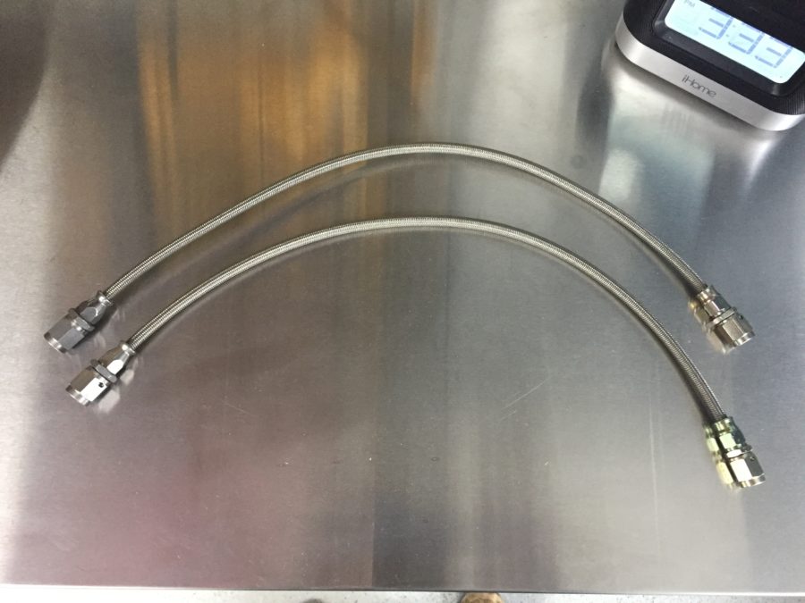
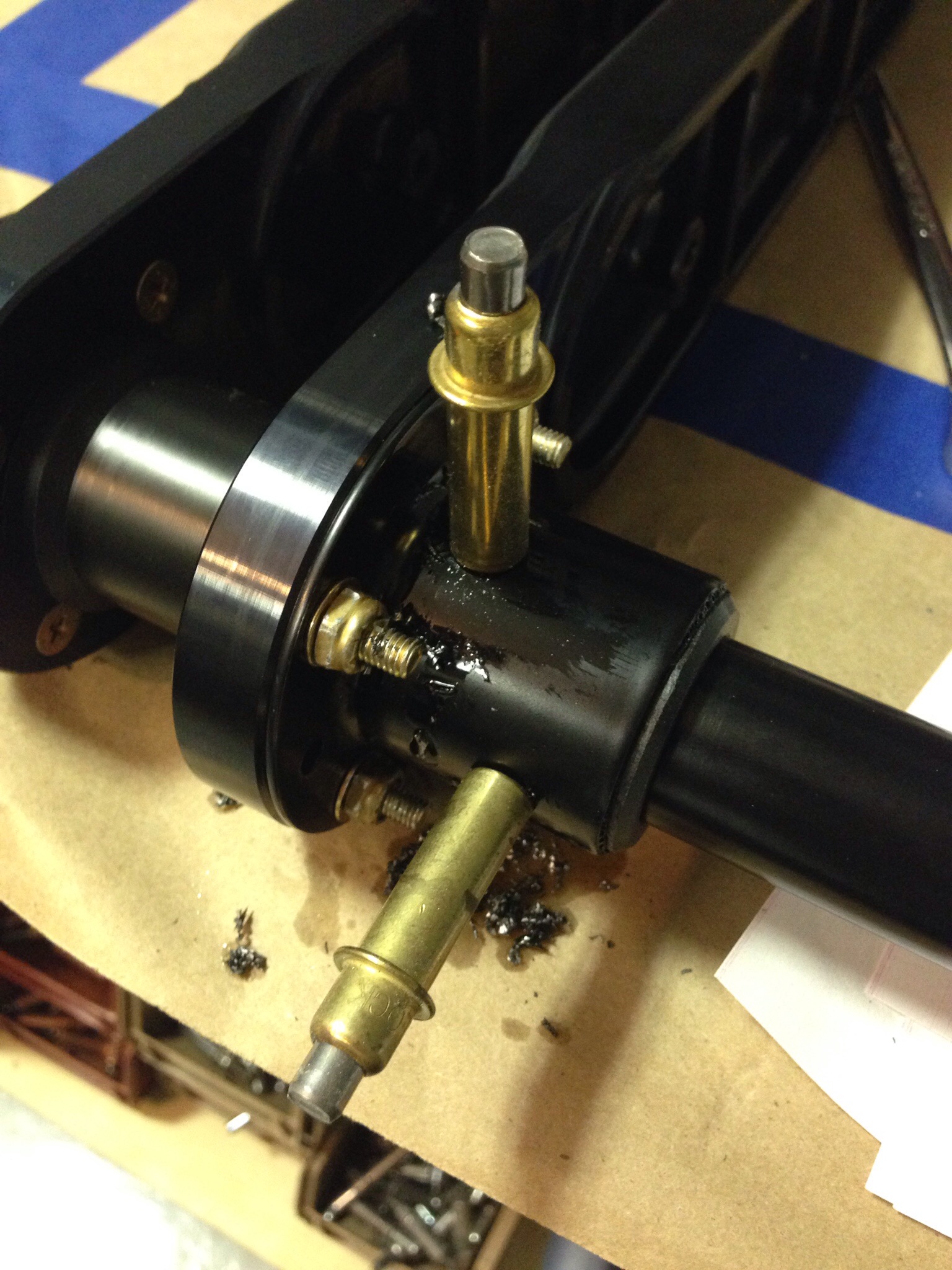
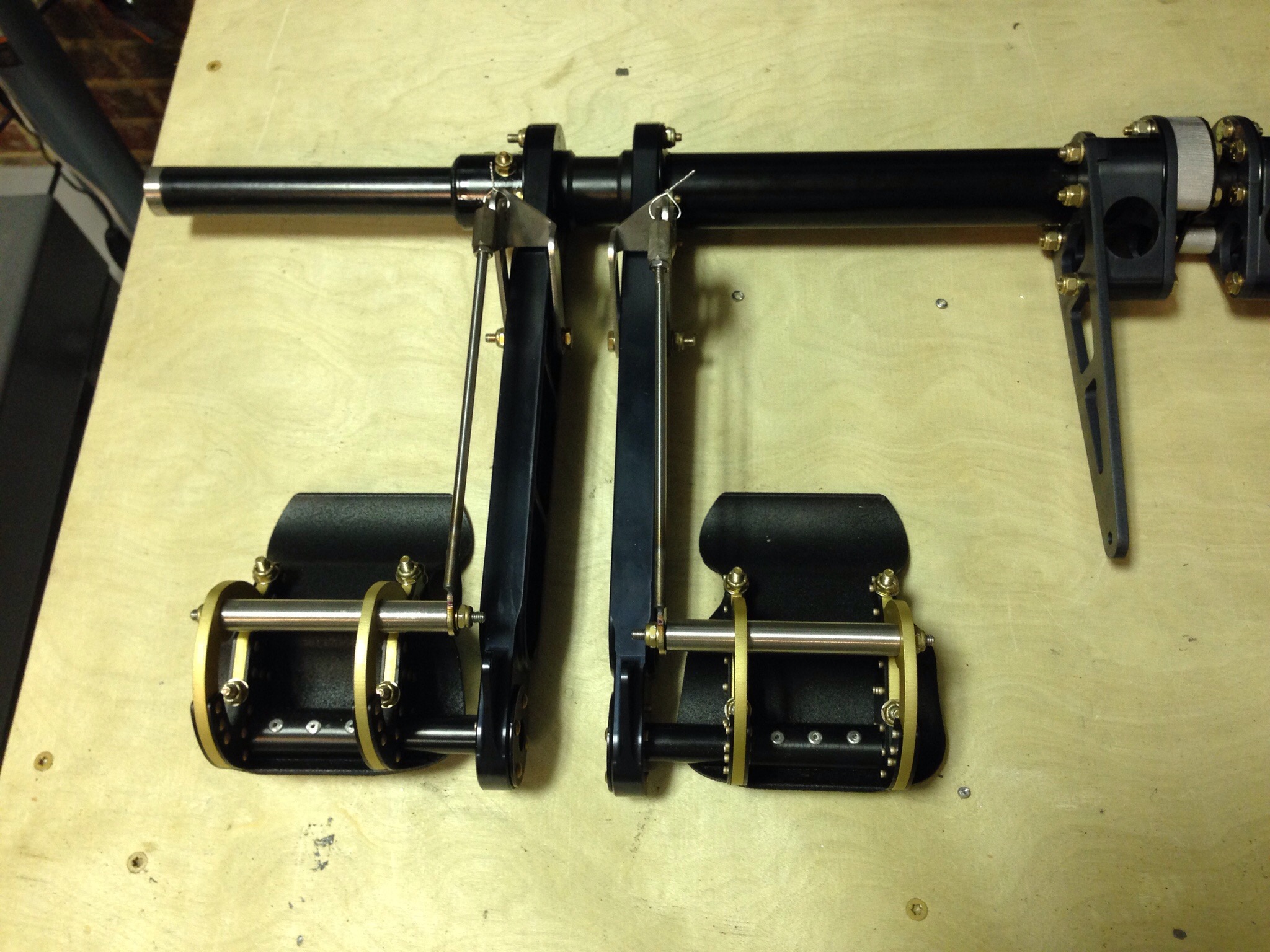
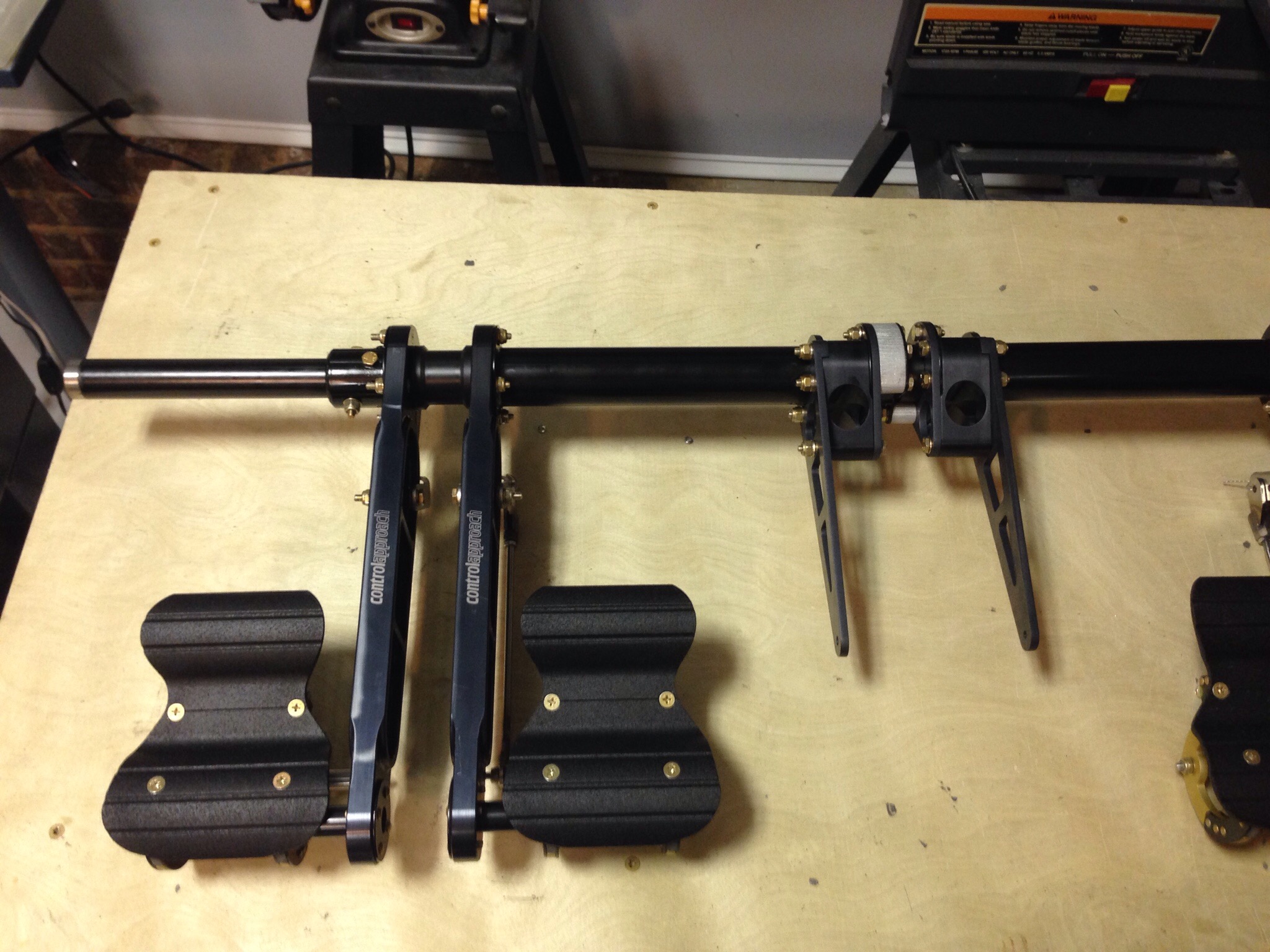
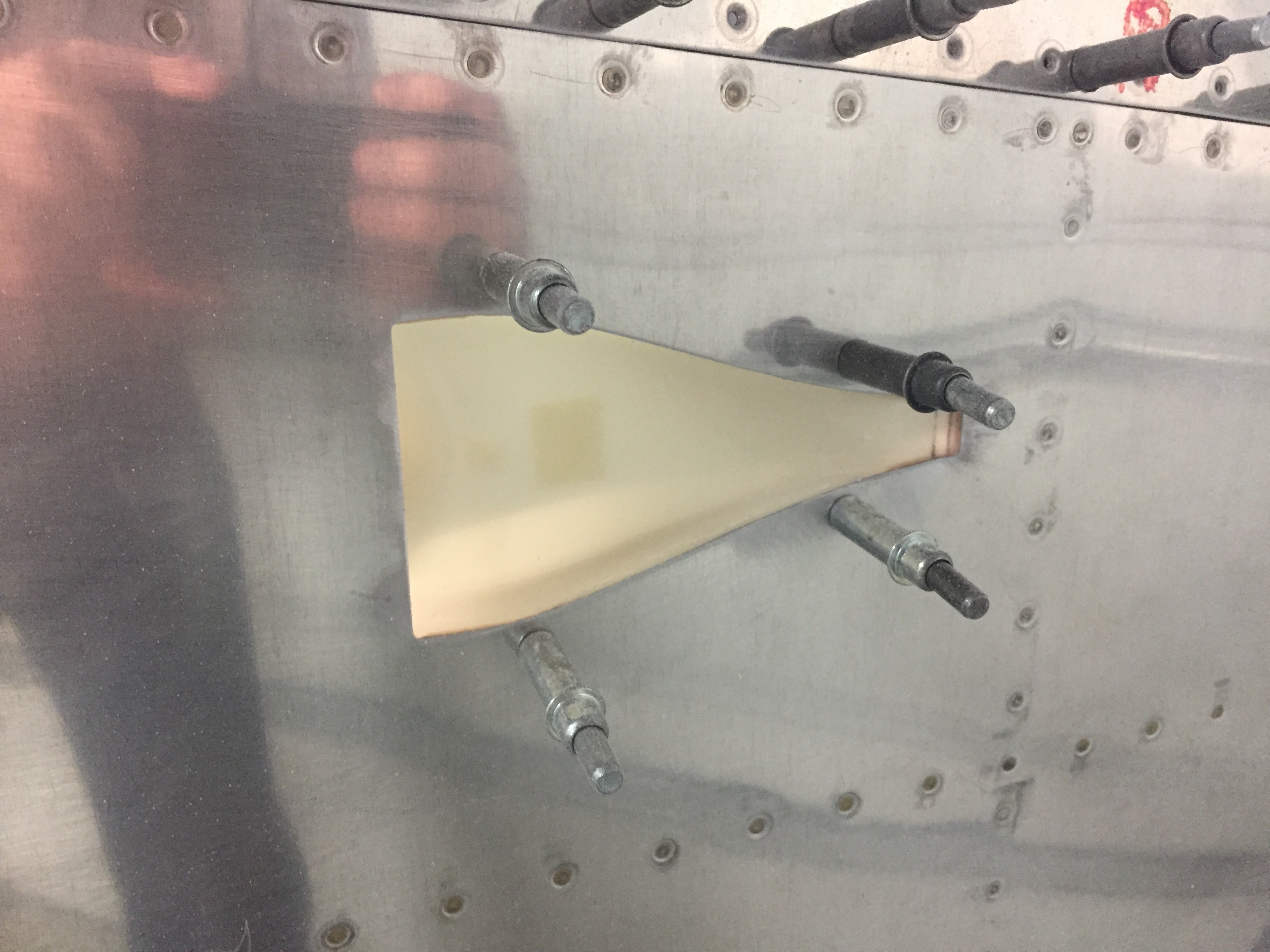
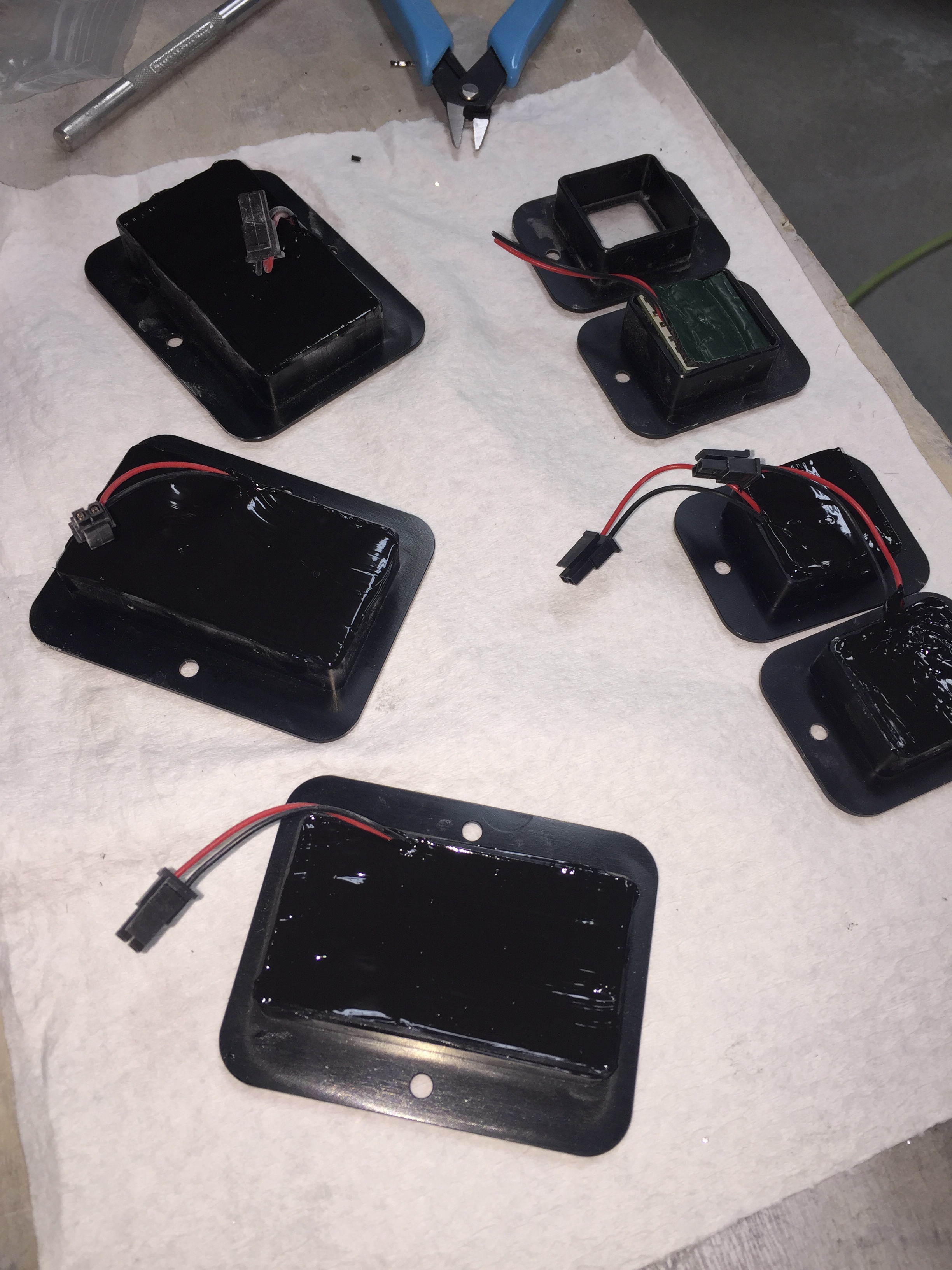
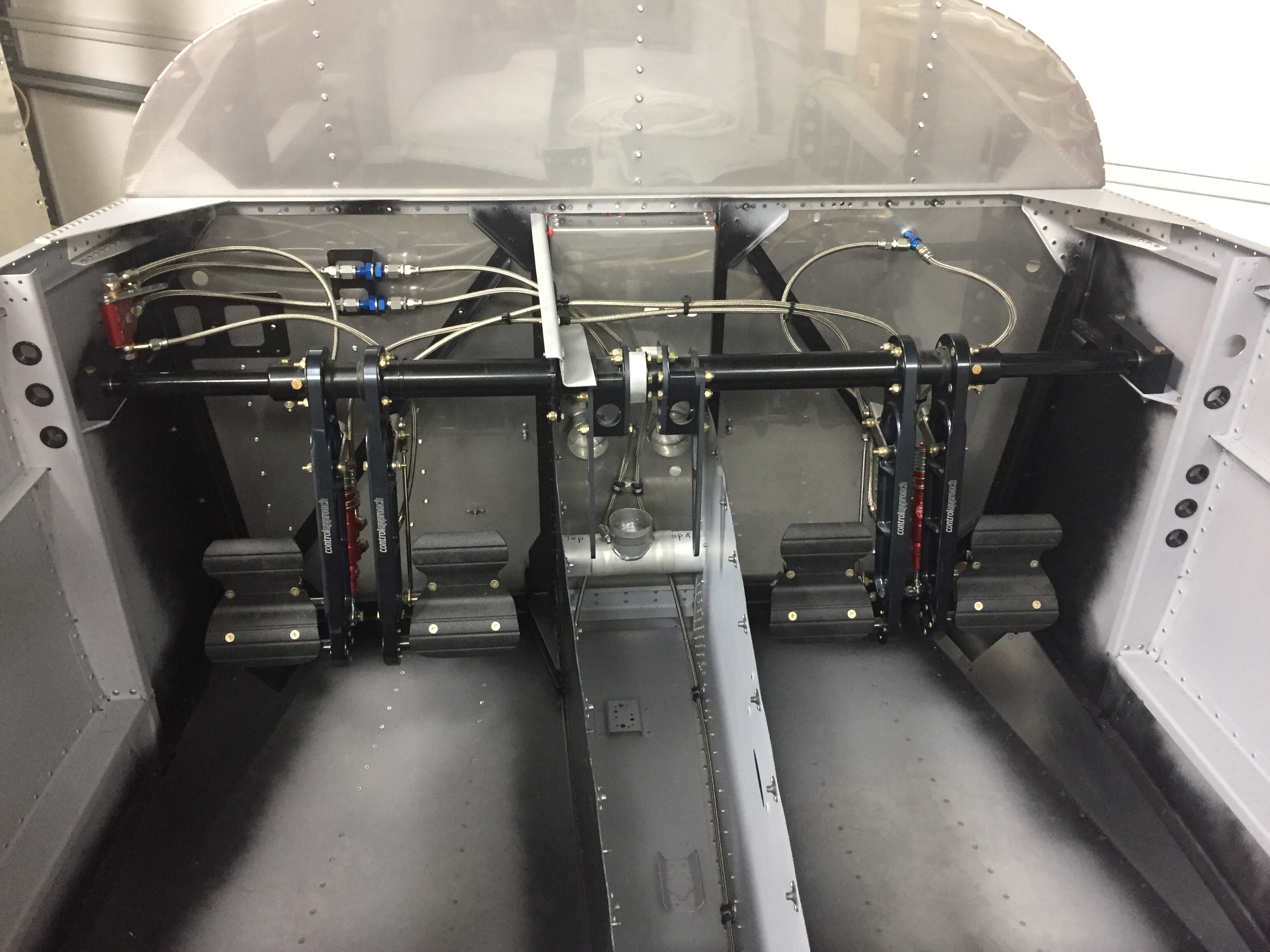
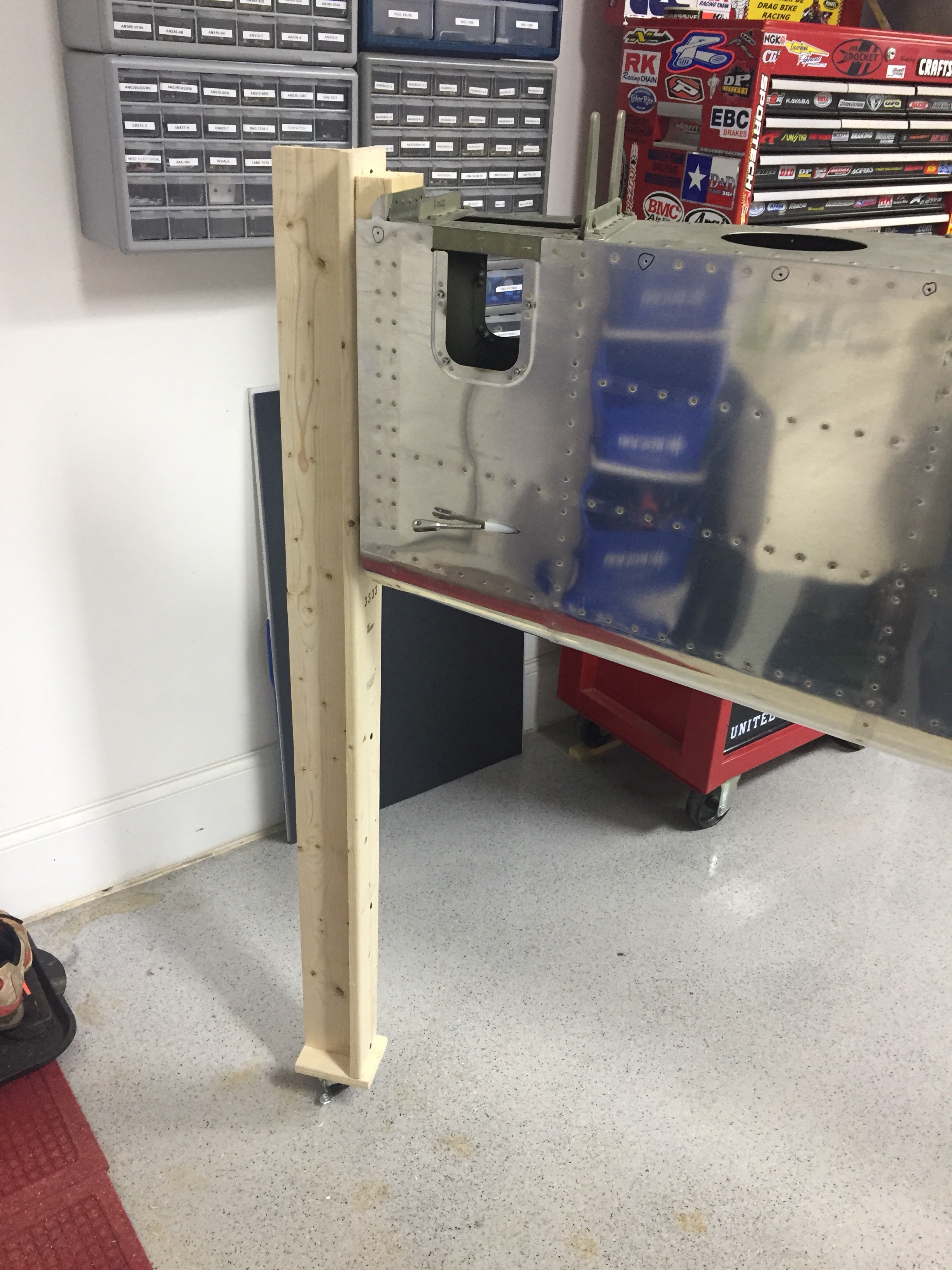
Inside the tail cone, I mounted the new static ports with pro-seal (no rivets this time) and hooked up static line that runs to where the ADAHRS will be mounted just behind the baggage bulkhead.  The new static ports look way better than the original ones and I’m happy I made the change.  The Safe Air 1 line kit makes it easy to run the tubing and create a leak free system.  I also ran the rudder cables through the bulkheads and snap bushings.  Ironically, the heads of the cables wouldn’t fit through the bushings without removing them and squeezing a bit.  So basically, the cables were a pain to run instead of a quick two minute job.  Lots of those in the build, I guess.   I got them hooked to the arms on the rudder pedals which are inside the tunnel with the Control Approach pedals.   With the A/C in there, it’s a tight fit for me!

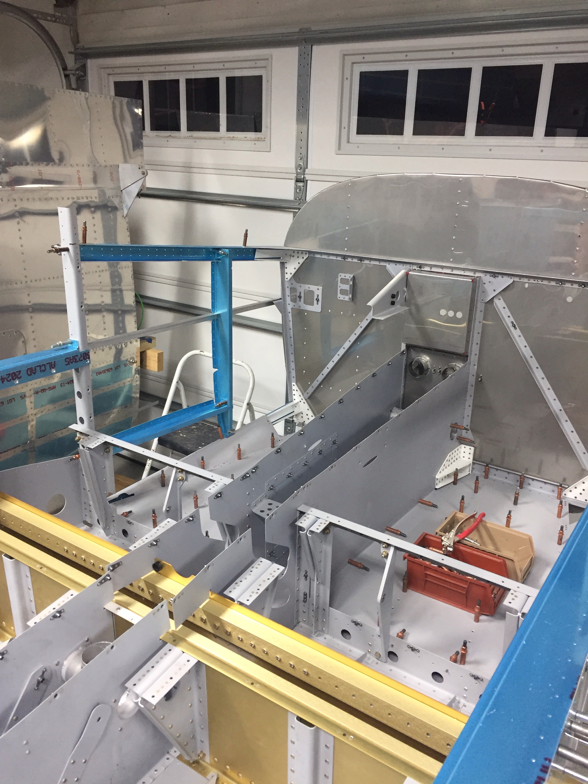
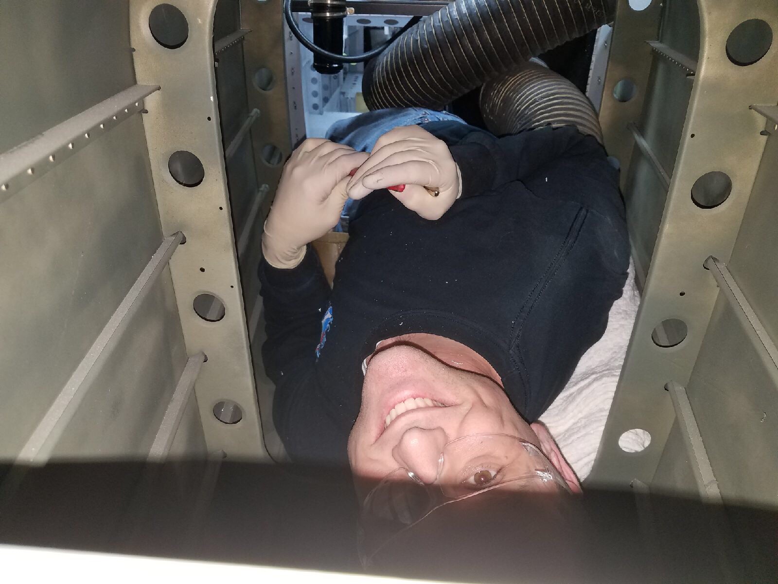
Lastly, I installed the doublers along the center of the fuselage for the transponder and ADS-B antennas to mount to.  These will be Delta Pop blades and mount with two studs, so I need access from the tunnel / fuselage.  Easy enough with a second set of hands to man the gun and me bucking.

Whoa, put the brakes on

It’s finally time to pull another beautiful piece of art work off the wall and turn it into an airplane.  The rudder pedals were next up in the plans and since I have the Control Approach set, it was a pretty quick fit in the fuselage.  I had to spend some time sanding down the tubes to fit into the mounting blocks to allow free but slop-free movement.  I also cleaned up the installation of the Beringer master cylinders on the pedals using some AN bolts and nuts instead of cotter pins.  This took some play out of the pedals while still allowing for free movement of all the components.

Before I put the pedal assembly in place for good, I wanted to paint the interior where the Aerosport panels may not cover the structure.  Per the plans, now is the time to paint the interior of the cabin.  With the Aerosport kit covering most areas, I won’t be painting all of the aluminum.  I also chose not to paint the stainless steel or put any insulation on the cabin side of the firewall but did mask off and paint the aluminum components on the firewall and the very forward area of the side panels.  90% of the work for painting is prep and it took a solid hour to mask off all of the firewall just for a few spots of color.  I’ll have a separate post about color and paint coming up.

It’s also time to start running brake and fuel lines.  Since I have the complete Beringer kit, I started fabricating the stainless braided lines.  The Beringer kit includes some really nice components and saves a lot of weight while providing a more effective braking action.  Sadly, it lacks a lot of detail in the instructions and was missing quite a few pieces.   The kit doesn’t include an inventory, so I wasn’t really sure what I had or didn’t have until I started putting it all together.  Another 10 builder reported the same issue and I believe they are working to improve the kit contents.  I will say that the customer service has been extremely swift and really pleasant.  All the missing items were shipped the same day I called along with a few extras that I ordered.  One disappointment is the use of the rigid tubing retained per plans between the firewall bracket and gear legs (the tube runs through the tunnel and under the seats).  I wanted all SS braided line so ordered extra hose and a few fittings that I needed.

The process is pretty simple to assemble the lines and the quality of the fittings instills confidence of a leak free system if I’m doing it correctly!  Time and tests will tell later in the build.  I am shortening most of the lines, as the Beringer plans have them conservatively long which actually create some routing / securing issues.  For now, I am holding off mounting the reservoir since I’ll be putting insulation on the forward side of the firewall.

A couple of oops

Mistakes are inevitable and I uncovered a couple of them back to back.  With the longerons fitted and finessed, the other structure went together pretty easily.  More bending was required as four forward channels required a good twist using the vise and a strong arm.  There are also quite a few other pieces that fit along the side forward of the spar.


A lot of match drilling comes next, as the longerons need holes drilled for the sill and skins.  A drilling template is used to drill holes for the rudder pedals and is where the first mistake was uncovered.  The longerons are not an exact science, so the guide didn’t line up perfectly.  A quick email to Van’s gave me guidance to line the template up with the edge of the longeron and all was well.  


Unfortunately the next mistake was not as easy to correct.  The engine mount brackets tie into the twisted channels and get drilled using the holes on the flange already riveted to the firewall.  I realized that three of the holes weren’t in the flange completely.  This is a major component providing support for not only the engine but the landing gear and forward fuselage, so certainly a cause for concern.


Van’s stated that it’s pretty common to have thin edge distance on these but all holes did need to be in the flange.  What I don’t understand and never got any response from is why the holes didn’t line up.  The mount is welded from the factory and cannot be bent or adjusted by the builder in the direction that is needed to correct the issue.  Replacement was my only option so an order to  Van’s was placed.  I am proud of my skills at removing the rivets, as I did not want to mess up the firewall.  All went well, though, and I’m just waiting for the replacement part to come in.

Let’s unpack

With a big wooden crate in the garage and fewer parts left on the storage racks, it is time to unpack the fuselage and get a bit more organized around the shop.

I was surprised at how well the individual parts were packaged in the crate.  I wound up with a massive pile of duct tape, shrink wrap, and paper!  However, I will say that all the parts arrived without a single damaged item.

There are a lot of hardware bags.  I took the opportunity to rearrange my plastic parts bins and finish labeling everything with my label maker replacing the masking tape and marker from the previous builder of the wing kit. It takes a bit of time, but makes finding parts really quick and easy.  It also helped me inventory all the little things.  After unpacking everything, my only issue was 40 AN3 instead of AN4  bolts.  A quick email to Van’s and they were on the way to me.

I put most of the sheet metal parts up on the racks above our garage door — man are those things earning their keep!   I went ahead and pulled down the last parts for the flaps, as those are the next project to work on.  The cabin top was precariously hoisted up to the ceiling for longterm storage  and some new brackets were put on the wall for the rudder and pedal assembly.   Speaking of, the master cylinders were the last pieces I needed to complete the rudder pedals, so I went ahead and installed them according to plans from Approach Control.    These things are a work of art and now they have a nice home until they get installed in the fuse..

Control Approach to my rudder pedals

RV-10 builders have drooled for years over ControlApproach rudder pedal set up and I am no exception. A few lucky guys picked up the available sets and Paul hasn’t produced them for a couple of years. I always kept an eye out for the classifieds for a set but had no luck. I decided to take matters into my own hands and reach out to Paul directly.

As luck would have it, Paul was filling promises and had a small production run with one set left. I weaseled my way onto the list and within a few days, had a set on its way to my house.

These pedals first of all look amazing. The design is much better aesthetically then the Van’s setup and goes along way to making the aircraft interior look professionally done. They are also awesome functionally, feeling much better (in my limited experience, one flight with and one flight without them) especially with the free-castering nose wheel on the 10. They relocate the master cylinders to the back of the pedal arms to clear up some foot space and eliminate hitting them with your shoes. They also move the rudder cables to the tunnel for their entire run.

While the machining and quality of the pieces is amazing, the directions leave a lot to the imagine. The box was well packed but the hardware bag was a bit intimidating!

IMG_1419.JPG
After a bit of organizing, it was much less messy and I was ready to get to work.

IMG_1420.JPG

IMG_1416.JPG
I had to re-read the directions a lot, but once I got a start and all the pieces laid out, it makes sense. A bit of jigging was required to get the four holes drilled for the inner and outer tubes that linked the pilot and copilot pedals.

IMG_1421.JPG
There is also a shortage of thin washers with the hardware kit, but I fortunately have plenty in reserve and most that I need are needed when installing the master cyclinders. I put everything together and securely stashed them away in the storage racks until ready for the fuse.

IMG_1425.JPG

IMG_1424.JPG