Never ending squawk list

The airworthiness inspection is rapidly approaching and it’s crunch time now. This post is about as fast and deep as all the stuff I had to do.

The awesome guys on based helped me bend my control sticks to provide plenty of clearance to the instrument panel. I still hit the flap switch in the full nose down, right roll position, but if I ever have to use that stick input, I have way more concerns about dying.

I never installed the tips on the stabilizers, so I wiped the decade old dust off of those and riveted them on then laid up some glass to enclose them. Some tweaking with the heat gun was enough to get them adequate clearance and I’ll let Jonathan do the rest of beautifying them during paint.

I crawled in the tail cone. Again. After I said, “Oh, I’m done back there, I won’t need to get back there.” Hell, at this point I can’t even remember why I had to go back there. I’ll flash forward and tell you that still wasn’t the last time. Either way, here’s how I feel about doing that little shit job.

The rest of the interior went in and lights hooked up. These side panels are pretty tricky to slide in without destroying the paint. I’m happy with how they turned out. The stainless screws also look really nice.

I pulled the plane out for a good GPS and comm check. I’ll have another post about the details, but while everything worked, I have some serious interference with the ZipTip lights and my radios. For now, though, no night flying means I’m safe and legal to fly.

The back seats and carpet are all in now. I had to put a lot of velcro down but man, this Aerosport stuff is amazing. The seats are comfortable, the carpet looks great, and I’m really excited about taking folks flying in this plane!

My cover from Bruce’s came in and is freaking sweet. Fits very nicely, has orange, and the tail number embroidered on it makes it so no one can steal it and use it on their plane without me chasing them down.

I put the cowling on for a final fit check and hooked up the new AeroTherm engine heater. I’ve used these on the Diamond we fly and really like it. I didn’t like the idea of cylinder heaters and want to keep the engine heated during the winter to avoid cold starts. I know this isn’t as portable, but I’m happy with it thus far. I did have to get a very thick extension cord so it would keep tripping its internal breaker with my crappy 15 amp service in the hangar.

Finally, I weighed the fat little piggy with all of the pants and random stuff not yet on for good in their approximate place. Folks, with full interior, oxygen, air conditioning, three screens up front, and all the extras my credit rating could buy, I’m pretty happy with her girlish figure. This let me sit down and compute weight and CG figures as well. Everything turned out nicely with an empty CG of 106.4 inches.

Firewall forward finishing

There is a lot of little projects yet to be completed on the firewall forward section, so I set about tackling them. First off was safety wiring the prop bolts. I thought torquing them were hard. Well safety wiring them is even worse. Because of the limited space, you actually have to loosen them a bit, thread the wire through the hole, then re-torque them. Ugh. Anyway, it’s not pretty but it’s done. I’m convinced this flange design negates the need to safety wire since they’d all have to unscrew in perfect unison for the damn thing to fall off anyway.

Here is a picture of the custom wrenches I had made up using Joe Key’s templates.

Since I was at the front end, I went ahead and finished up the spinner installation. The back plate takes some time to bolt on as well with 1300 bolts used to hold it to the prop hub. The spinner has three plates behind the blades to fill the gaps and it took a bit of dry fitting to figure out where each one goes. WW had labeled them by number and I was wrongly lining them up with blade numbers not just the reference number on the spinner and back plate. The front of the prop hub fits into a bulkhead in the spinner and it took a few iterations of Teflon tape and sanding to get a nice snug fit with no wobble of the spinner.

The air filters were the last step for the intakes and I had been waiting on a different filter with a tilted base, allowing clearance of the tube to the filter assembly itself. This was required because of the blister I had to glass in for the air conditioning compressor. Fortunately a 10* tilt made just enough clearance and it all fit together nicely. I oiled the filters and got them put on for good or at least until the first annual.

The right intake tube is close to the exhaust, so I used some heat shielding that has an adhesive back to protect the tube. I went back and covered this with 3M foil tape and then applied RTV around the edges to secure it. I’ll monitor this during ground runs to ensure enough protection from the exhaust header.

Since I had RTV all over me anyway, I took the opportunity to finish seal up a few spots around the engine and firewall. I have spent a TON of time trying to find any little spot air could leak out of the baffles that it shouldn’t be leaking. Since the hangar is dark with the lights off, I again used a flashlight on top of the engine to highlight any little spots. It worked great and I’m hoping it pays off with adequate cooling once flying. It’s impossible to be super clean and fancy with this stuff, but I kept most of the mess on me instead of on the engine.

So many of my electrical connections are oddly shaped so getting a boot to fit hasn’t been easy or even possible. I used a 3M product to paint electrical tape onto the hot studs just to keep a surprise shock chance low. Not quite as good as boots, but better than nothing.

Lots of zipties up front still being added as I just see spots here or there that could use some extra security. I may add wire wrap that is rated for high heat to clean it up, but not sure if I care or want to spend the time on that quite yet.

Multi-tasking is key at this point so I setup the vacuum pump on the aircon system while RTV was setting up. All of the lines and connections are secured so I could finally vacuum the system to perform a leak test and evacuate moisture from the system. The ports are just behind the baggage bulkhead and pretty easy to get to. I set up the pump and let it run for about an hour and a half to get moisture out then closed the pump off and let the gauges sit all night long. The next day I returned to see a perfect vacuum still holding, so that is a huge win!

The last two projects up front were some additional glass work on the plenum and a ramp for the aircon compressor. The plenum was designed to be sealed to the cowl around the oil dipstick, but I didn’t like the idea of air potentially leaking out of the plenum through the oil door or into the engine area. I cut up a sports drink bottle as a mold and roughed up a little funnel to fit over the dipstick. The dipstick will have some foam tape sealing the bottom of the funnel. It didn’t come out as pretty as I wanted, but it’s functional and I can always clean that up a little down the road.

The air ramp was a little easier than I expected. On the left side intake, the aircon compressor causes the cooling ramp and induction intake to need a cutout and I wanted to create a little blister to help direct all the air possible into the cooling and intake ducts. I shaped a foam block and used packing tape to secure it to the cowl. I used some carbon fiber to lay up a rough fairing then cleaned up the edges after it set up. This is attached via two screws and should provide a nice air flow deflection that is simple to use. I plan to create a final piece of bulb seal to fully seal the cowl to the engine portion helping minimize air pressure loss while providing flexibility for engine movement.

Wipe the cowl off your face, we’re moving!

Thanks to a great guy on base that has a side business of welding, I had my AFR (O2) sensor bung welded on the exhaust per Ross’s recommendation on location.  I chose the #6 cylinder, but he said it doesn’t really matter.  I chose that one since it fit well there.  The sensor has a controller that I attached to the engine mount just above the battery box.

I never have been able to wrap my head around the nose gear fairing made by Show Planes until I physically put it all together.  The idea is to not only support the lower cowl around the exhaust openings (and air exit) but also smooth the exiting air flow around a turbulent area.  I started by attaching the front and rear fairing together and then positioning it roughly on the lower cowl.

The rear piece has a few lips that fit over the bottom skin to help locate it correctly, so I did an initial fit before starting to trim the nose gear slot.  Bryan shows a very tight opening for the gear leg, but I’m not sure how much it actually moves, especially on a grass or dirt strip, so I’ll leave a bit more room.

Once initially trimmed, I drilled into the bottom fuse and used nut inserts vs. sheet metal screws.  I figured it’d give a better grip long term and less chance of stripping holes.  Once the fairing is on, it reminds me of a duck billed platypus.  Ha!

I chose to use more SkyBolts to secure the fairings to the cowl.  I am also following Joe Keys’s lead on making a cover plate to cover an extended nose gear leg slot.  This will allow the cowl to fit a bit better going on and coming off since I have the dreaded three blade propeller.

I finished up by extending the cowl slot as far as possible while still covered by the fairing and epoxied the front fairing onto the bottom of the lower cowl.  Getting the lower cowl on and off is a bit of a challenge, but it does just fit and the blade sox I have really pay off here to avoid nasty scratches on the prop blades.  

Since the cowling was the last big project left to complete at home, the fuselage is ready to join the wings at the airport!  I was able to complete all of the interior, electrical, avionics, and engine including cowling at home which saved a lot of time and money in the long run.  Now I need to fit the wings and tail surfaces to finish up the build and need the hangar space to do so.

On a sunny afternoon, we rolled the fuselage out and did a good blow job (hahahaha, grow up) to get most of the dust off of everything.  I found a roll back wrecker driver that made me feel comfortable and who wasn’t in a hurry to move it the few miles to the airport.  He did a fantastic job, talking through each step and making sure I was happy with how we winched it and tied it down.  He took his time on the curvy bumpy back roads after managing down our driveway of doom and destruction with ease.  I think I breathed twice during the 45 minutes it took to move it and I only panicked once when I thought tree limbs were going to scratch the windscreen but were actually three feet clear.

We rolled it off the wrecker onto the ramp and quickly had it tucked away in her forever home at IPJ.  Laura helped me roll the wings still in the wing rack down from the other end of the field (a 20 minute walk with those puppies).  Two guys who I know flying the Diamond were kind enough to let me store the wings for almost a year in their hangar free of charge.  Truly great people makes things like this happen, can’t say enough.

About five trips later, we had all of the tools, parts, pieces, dust, and components all in the hangar.  For the first time, everything is together in one space that will be a flying airplane very shortly!

Insert witty title here – baffles, oil door, random stuff

The baffles are all trimmed up and ready for a coat of high temp engine paint.  Looking back, I wish I had them powdercoated, but too late now.  They’ll get scratched up and at least this way I can touch them up, similiar to my mentality for the interior.  The front ramp area was trimmed significantly for the air conditioning compressor and turned out pretty nice.  I removed the front fence on both sides, as others say there is no point in them.  I can always add a bit of tape later to warm CHTs up if needed.

The rods that hold the bottom of the baffles together were a bit of work, as you have to put some bends in the rods and then thread them.  I’m using these as mounts for the sensor wires as well as a few other wires including the starter wire and alternator b lead wire.  It really cleans up the wiring nicely and keeps everything tucked away.

With each connection at the engine, I get to verify functionality by turning on the avionics and looking for realistic numbers.  For instance, I now have 14 different temp sensors all telling me the garage is in the low 70’s!

I fabricated up a bracket to mount the throttle cable to for the throttle body.  It routes under the bottom of the engine and since it’s not exactly a stock setup, there is not stock cable mount.  It was a pretty simple fix with some angle channel and a few bolts.  I am thankful I ordered a lot of various 1/4-20 bolts for the engine case since they are not standard AN bolt threads.  The throttle cable is now attached and rigged with good travel on the throttle body and throttle lever, so I’m 50% complete with engine control cables.

The prop lever didn’t work out so quickly or successfully.  After I mounted the Show Planes bracket and hooked up the cable, I began to wonder why the governor is sprung to low rpm/high pitch.  Yeah, oops, no, that’s not right.  The governor can be configured a few different ways including rotational actuation and mine is backwards.  I called Whirl Wind and as always, they took great care of me.  I sent the governor into them and they shipped it back corrected the same day they received it.  Now it is sprung to high rpm/low pitch as it should be with proper activation with the cable.

In an effort to reduce the crap on my workbench, I decided to wire the spark plugs and coils to get rid of two big bags taking up room.  I ended up re-configuring the mount for the coil connections on the top case mounted coil and it made running the signal wires cleaner and easier.  The plug wires themselves were pretty easy and quick to run now that I have the MSD crimp tool.  The biggest challenge was deciding how to route and secure the wires.  I’m pretty happy with some Amazon plug wire organizers and a few adel clamps.

Since everything inside the baffle area and the baffles now on for good (thank goodnes, they are a pain to get on and off a bunch), I could test fit the plenum, ducts, and cowling for the first time.  Boom, it all fits!!!  The plenum is just clear and will allow a bit of shake room for the engine within the cowl.  The intakes and cooling ducts clear the inlets by about 3/8″ and I test fitted the bulb seal which I think will work nicely.  Everything lines up nicely and I think it’s going to work out to a clean and effective installation.

I will need to check the oil from time to time (it’s a joke folks) so the oil door needs to be fabricated.  I have the hidden hinge from Cleveland Tool and planned on using Cessna push button releases for the fasteners but decided against them once I got them in hand.  I just don’t like how they work or look.  I want it convenient to pop that door open and thus will sacrifice looks a bit for functionality.  I ended up ordering the winged Skybolts.  The releif area was cut out using the cutting wheel and I realized that I didn’t leave enough of a flange to mount those Skybolts.  I test fitted the top cowl with the plenum on and ensured there was plenty of clearance for access to the dipstick and then fiberglassed on more of the flange to correct the issue.

The door itself is a perfect mold and only required a bit of sanding.  The stiffner was epoxied on with West epoxy and a bit of flox to add rigidity.  Once it cured, man it is super stiff!  I let it cure on the cowl with clecos to get good form.  Installing the hinge was pretty simple, just a bit of adjustment to get the hinge point located properly and the spring will allow the door to stay open easing access to the dipstick.  I’ll lay up a funnel shape to enclose the dipstick tube and seal the opening in the plenum in a bit.

Finally, I knocked out a nagging job with the air conditioner.  The condensate drain wasn’t routed to the exterior since I redid the ducts in the tail so I had to come up with a way to allow that water to drain out.  I experimented with a fuel tank bung that I had surplus and a short piece of tubing.  It equaled a great fitting vinyl tube with aluminum tube insert threaded into the bung and riveted to the bottom tail skin.  I put an angle cut on it to help create a low pressure on the tub which will help suck the fluid into the airstream.  Elegant solution, if you ask me.  I know, I’m incredible aren’t I?  So humble too.

I really foamed that up

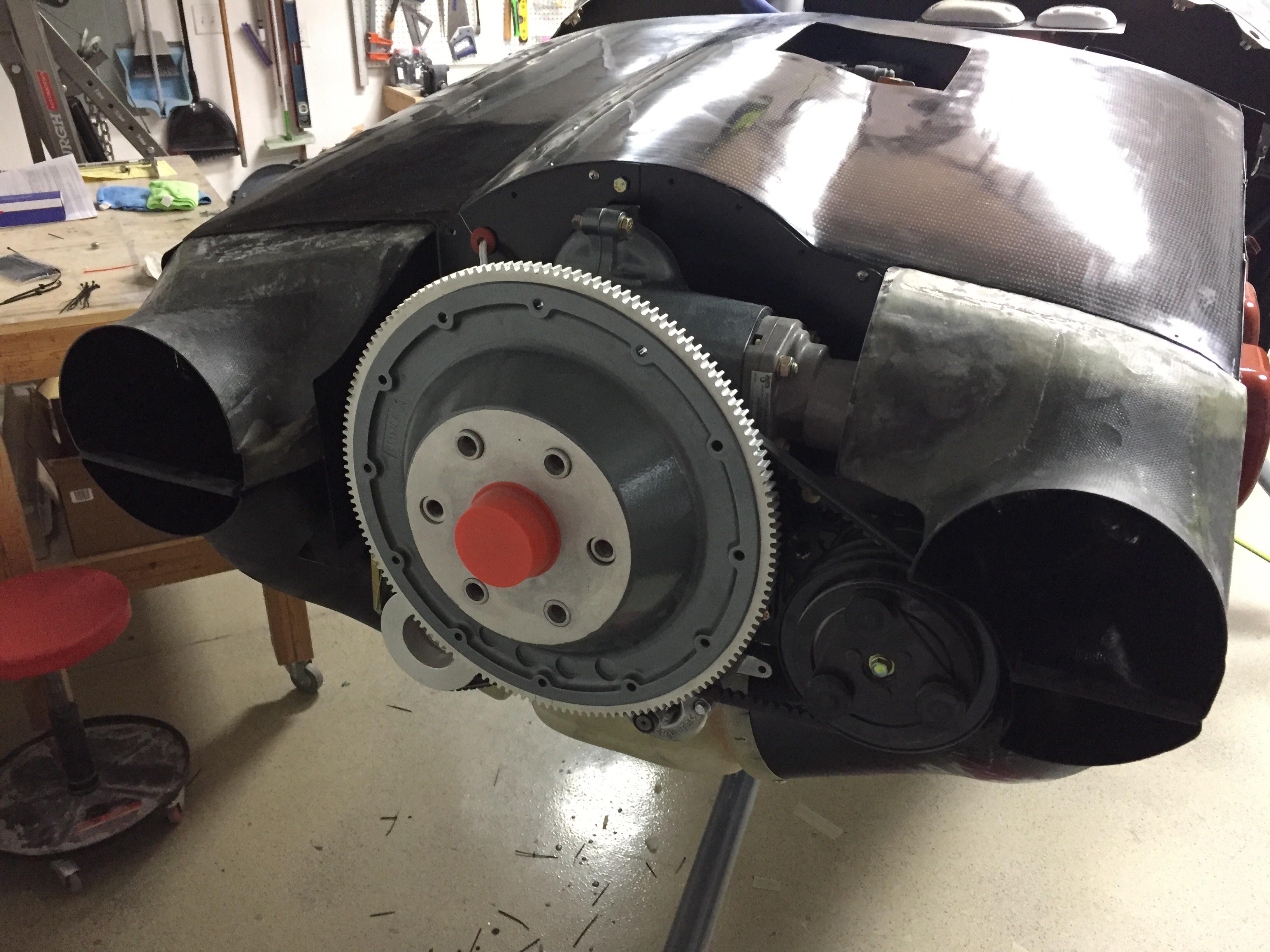
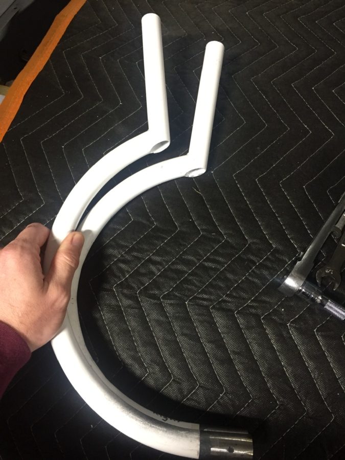
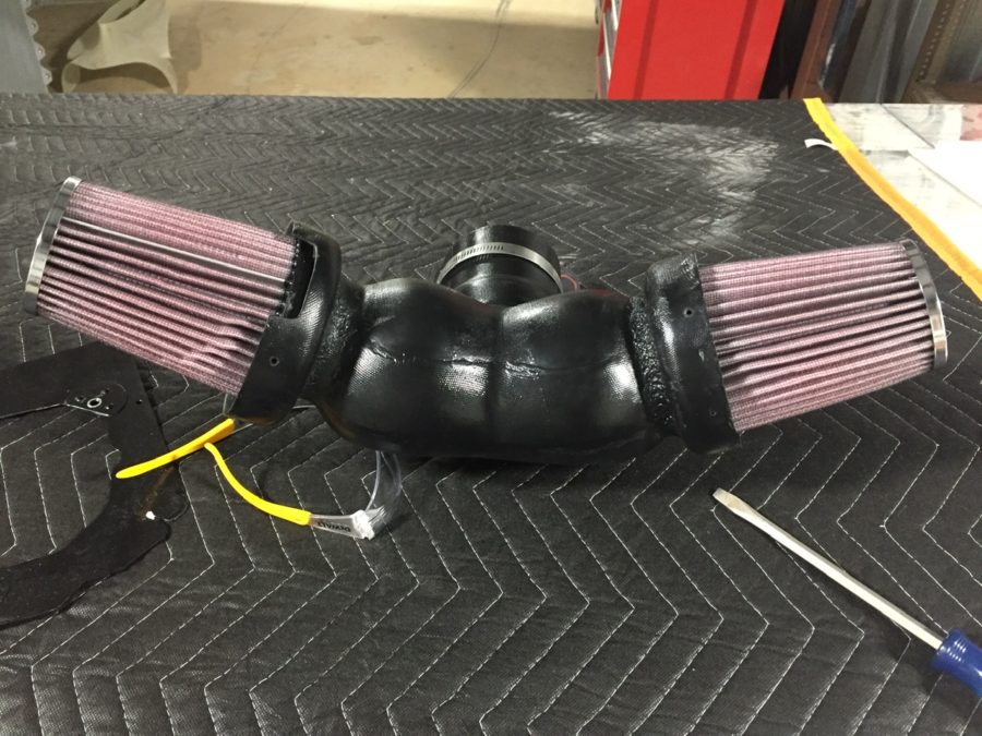
Now the cowling is fit, some tricky bits come up on the to-do list including the engine intake ducts and cooling ducts.  All of these are complicated by my air conditioning and plenum choices.  If I get it right, it’ll be magic and a work of art.  I probably won’t get it right the first time, as some of you may have guessed.  I started with getting the engine intakes started.  These start at the cowling openings and form the bottom 1/4 of the opening.  they curve inward and join a Y that holds two K&N air filters before hitting the throttle body.  The ducts are well molded and nice light but strong fiberglass.  The problem is they don’t fit very well with the exhaust and other accessories on the engine.  The Show Planes instructions leave a lot to be desired, but once you piece the components together, it starts to make sense.

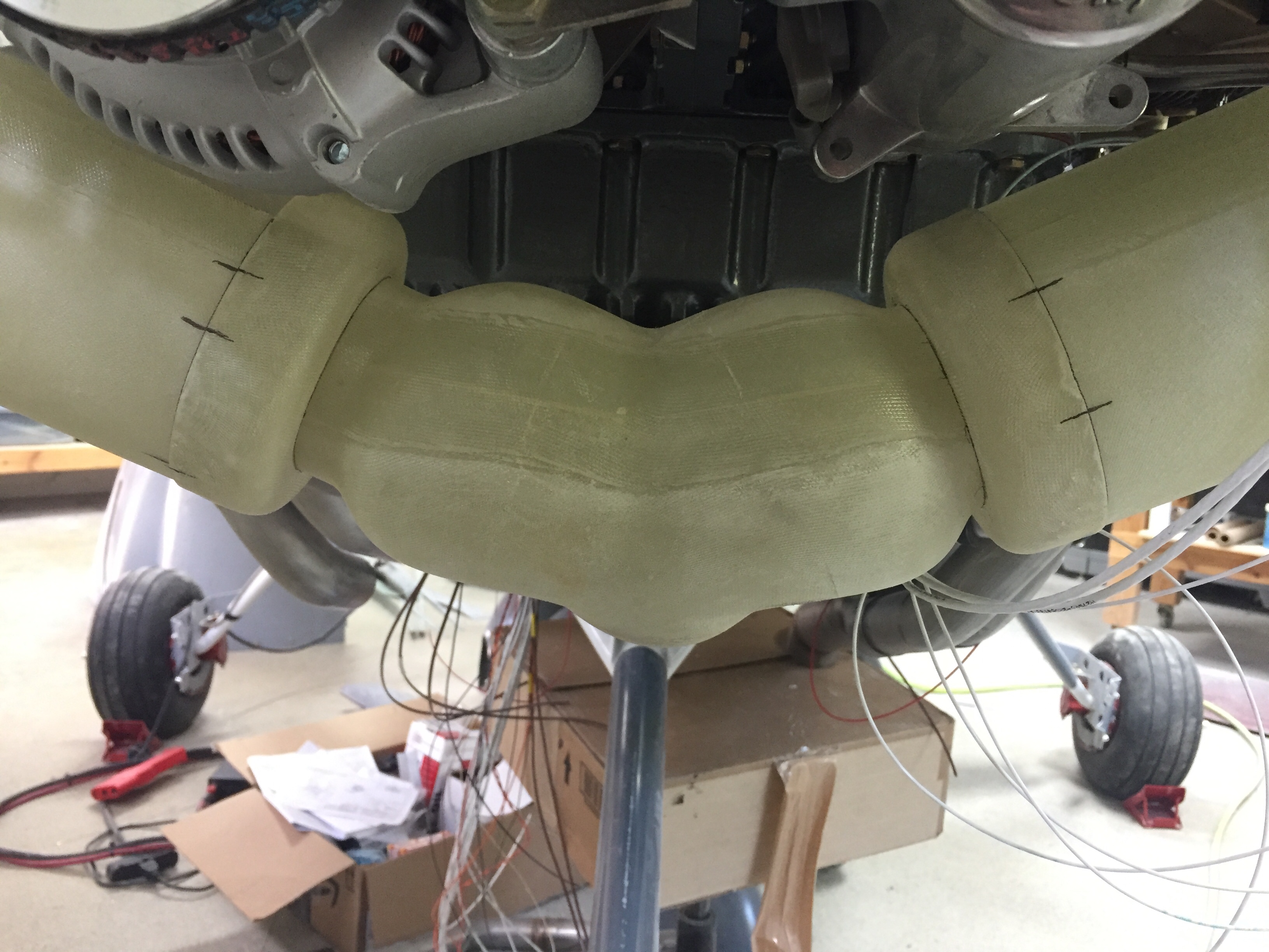
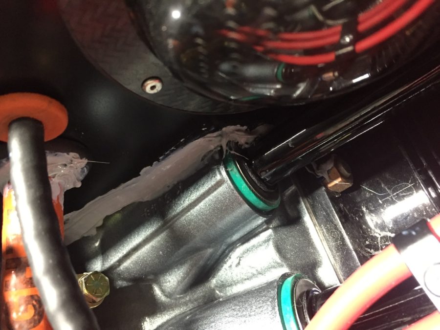
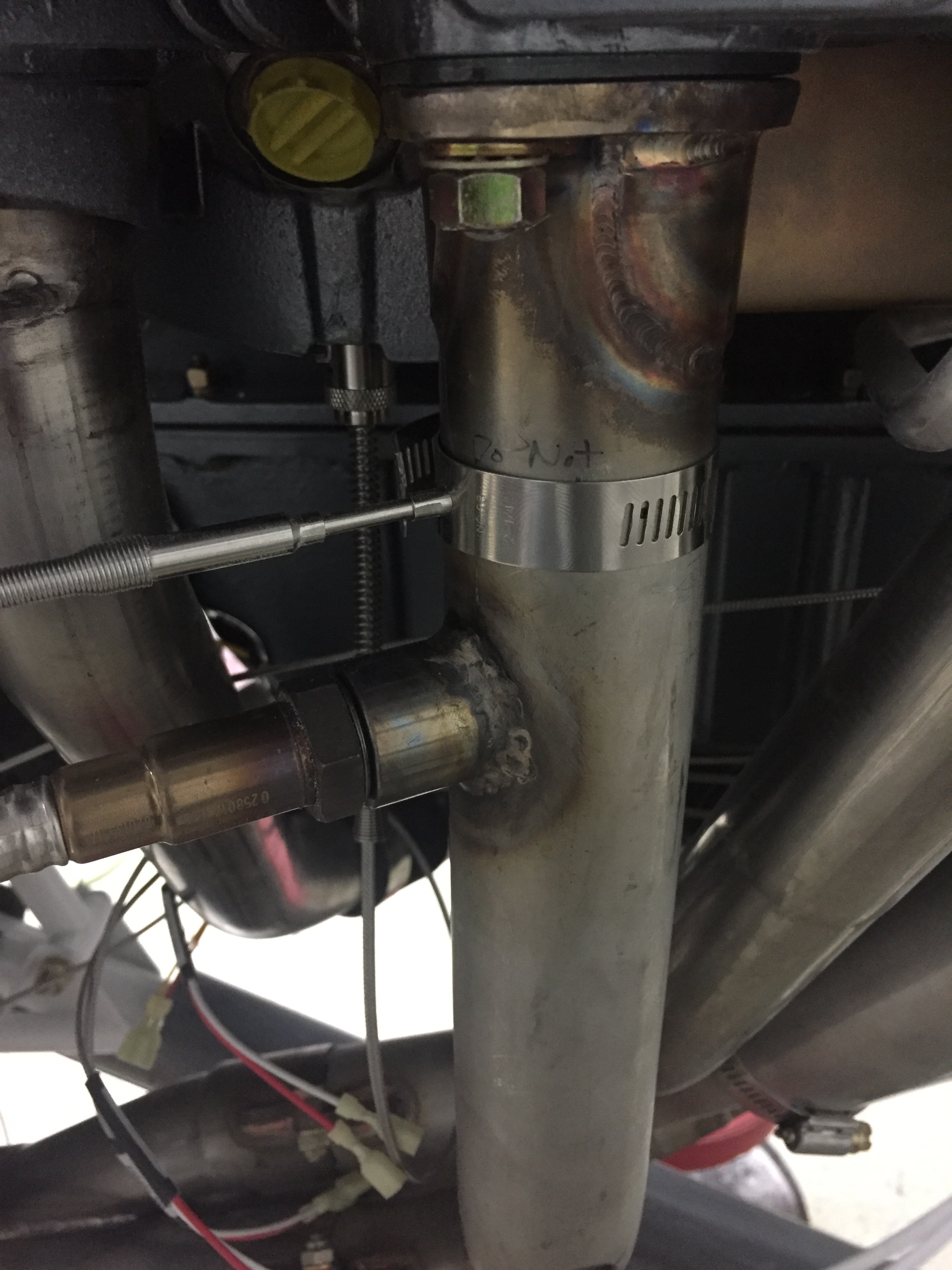
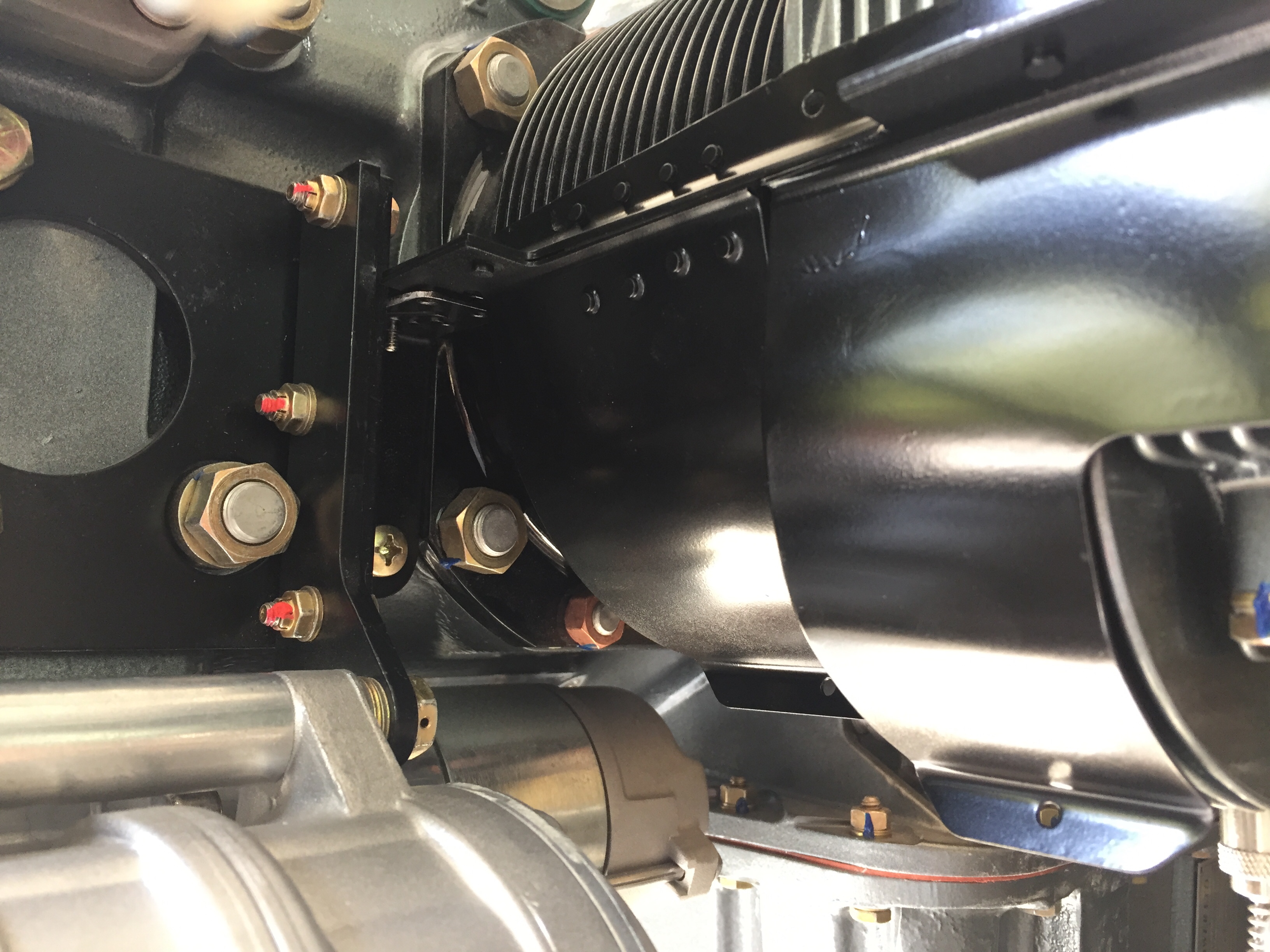
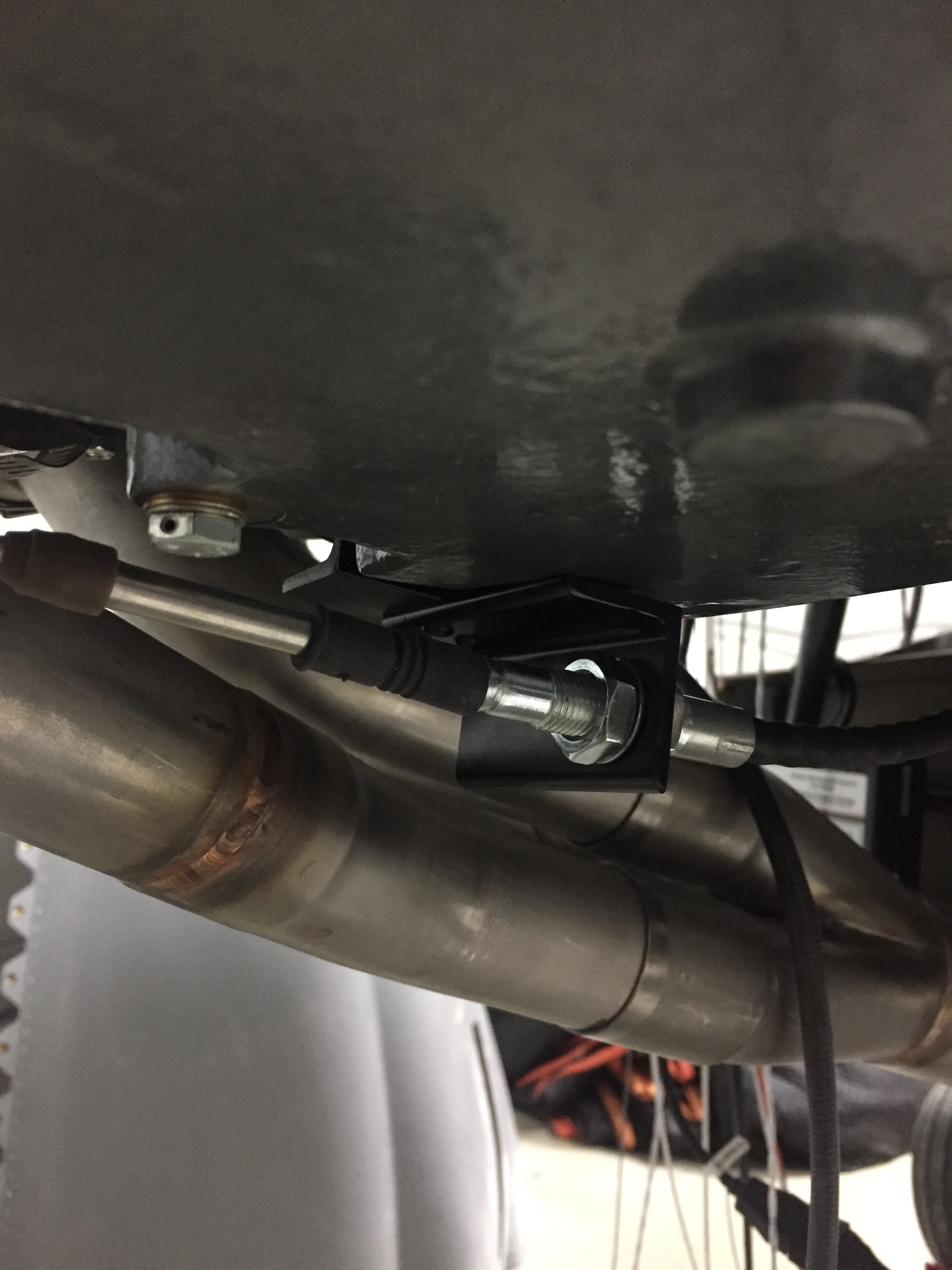
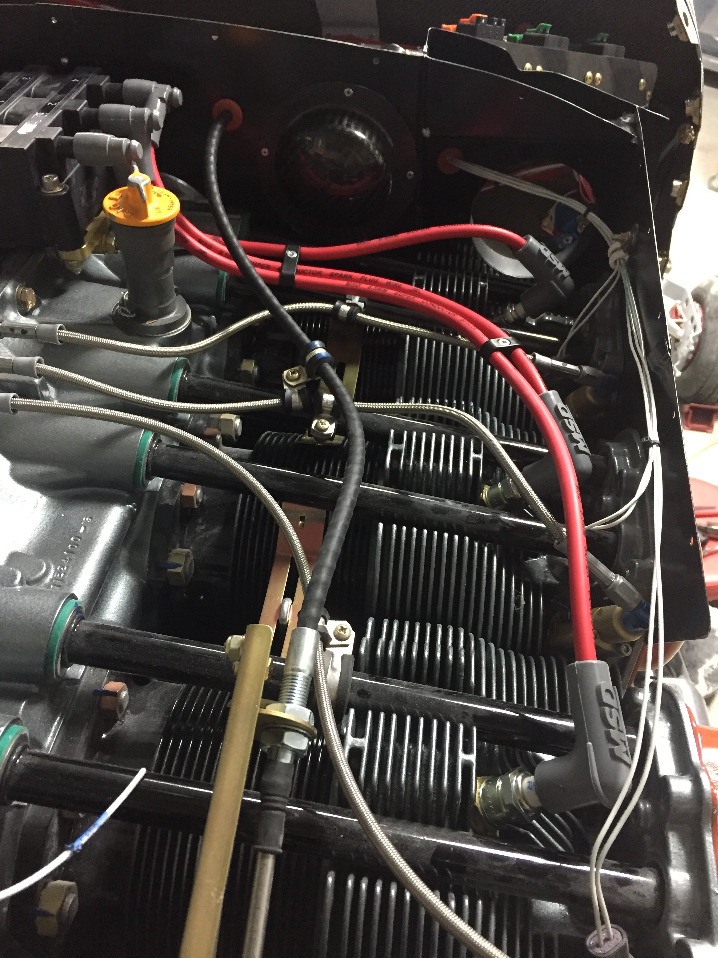
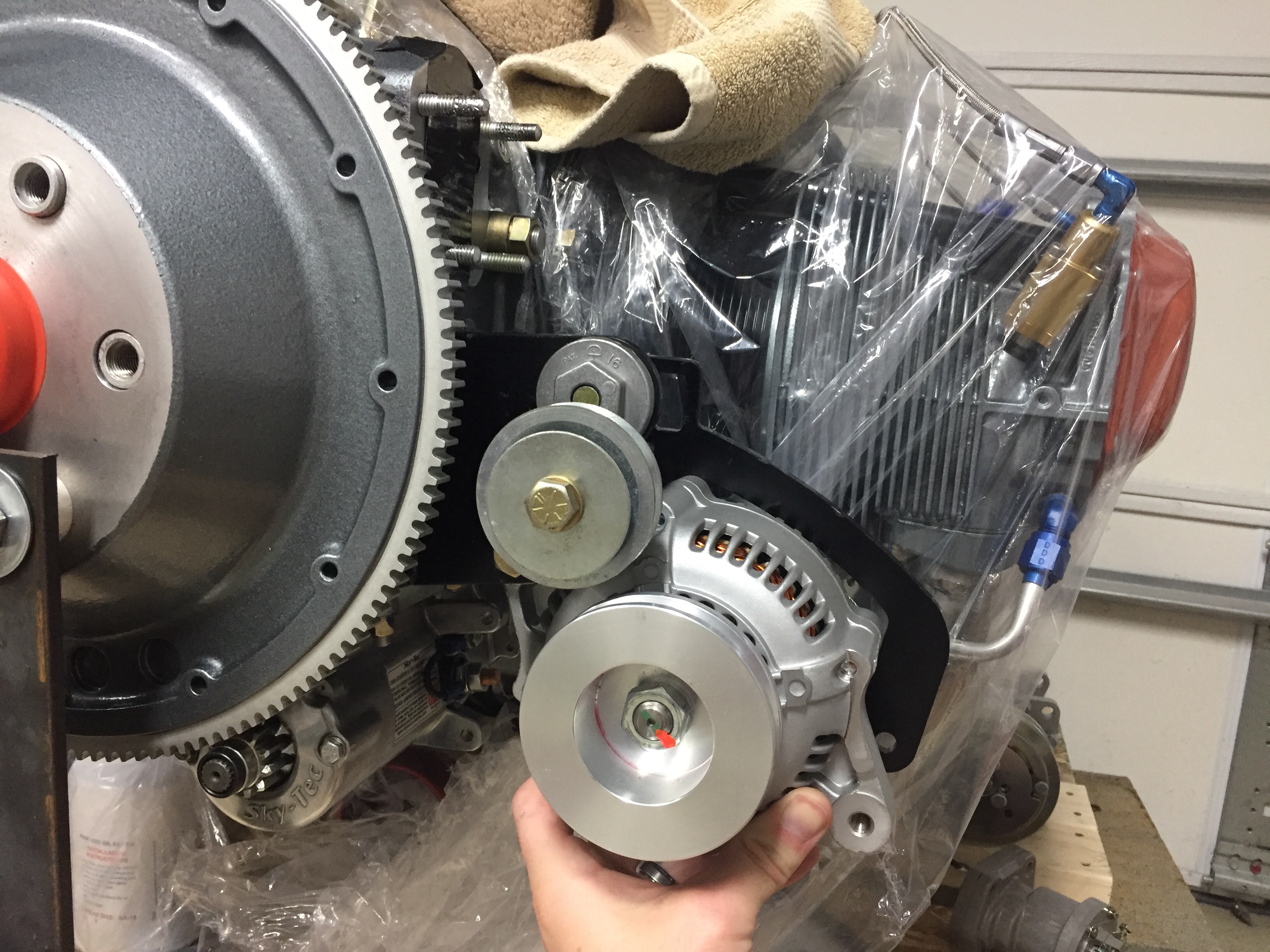
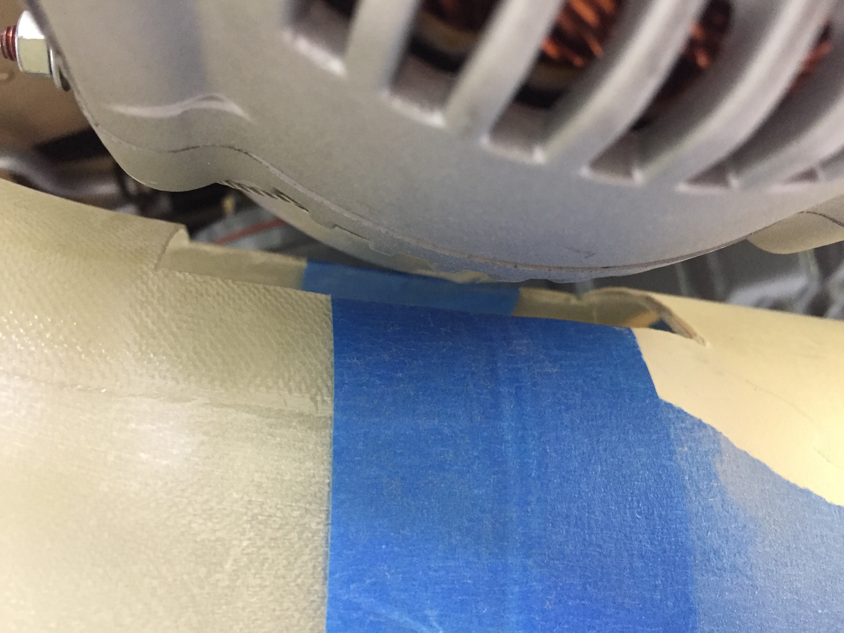
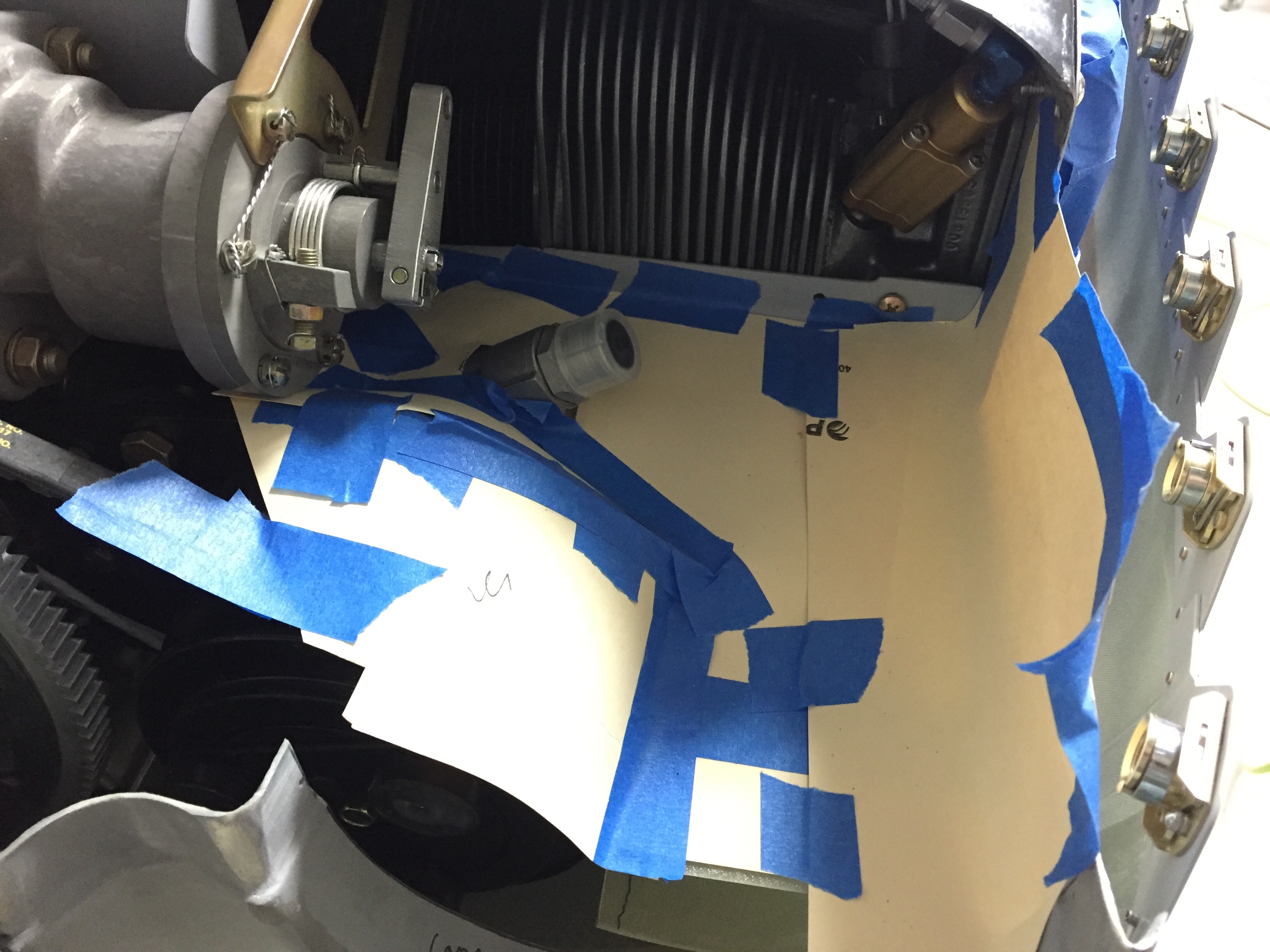
I first had to cut a relieve for the alternator.  Not sure if it’s just the Plane Power or if all alternators will require this, but mine was about a 1/2″ too low impacting the right duct.  Next, I had to trim quite a bit for the exhaust coming from #2 cylinder.  I tried to get a good 1/2″ to 3/4″ clearance and will using some heat shielding to protect it from the close proximity.  

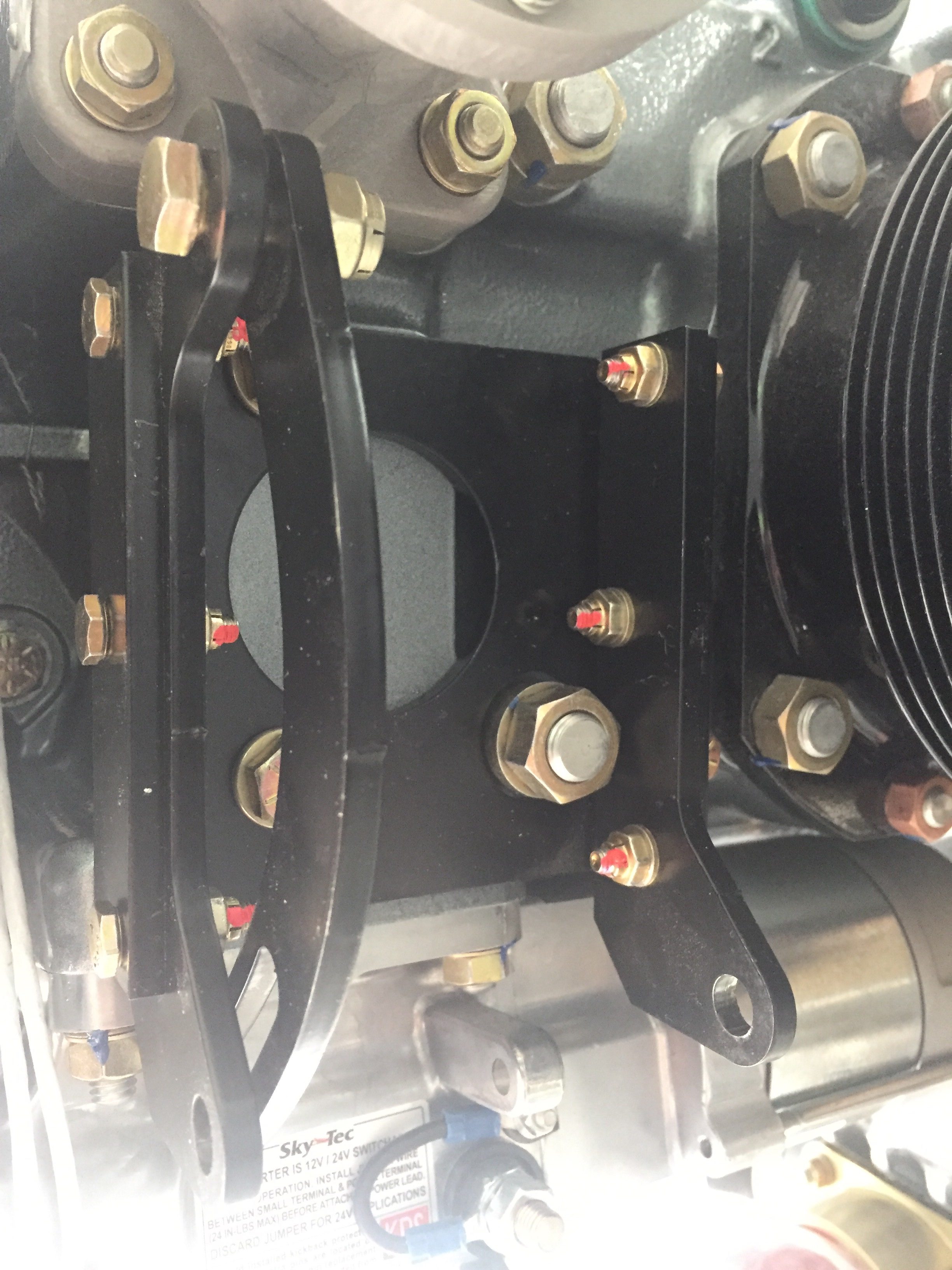
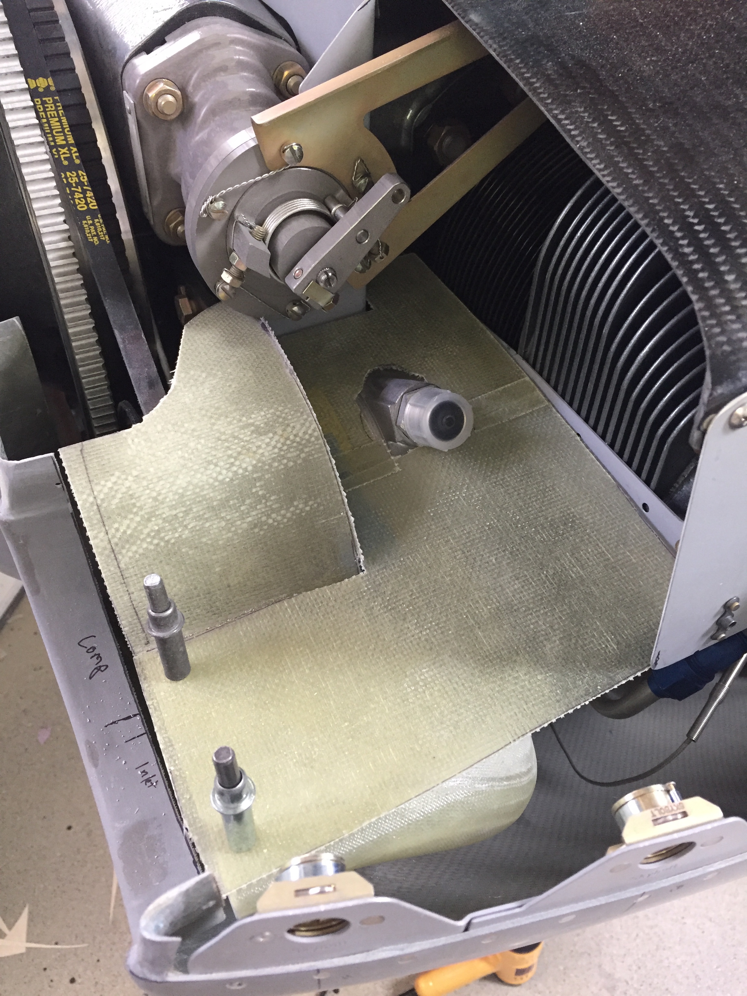
On the left side, the air conditioning compressor dictates a much larger modification.  Gaylon wound up elimintating this duct all together but I want to at least try to keep it.  The problem is the compressor blocks some of the cowling opening and thus reduces not only intake air flow but cooling air flow.  I’m hoping since I have a plenum and will have the cooling intake completely sealed, that the minimum reduction won’t interfere with adequate cooling.  Time and testing will tell.  I also want to keep the left side induction to maximize manifold pressure thus power and performance of the engine as well as keep the redundant induction air supply (think alternate air on the stock setup).  

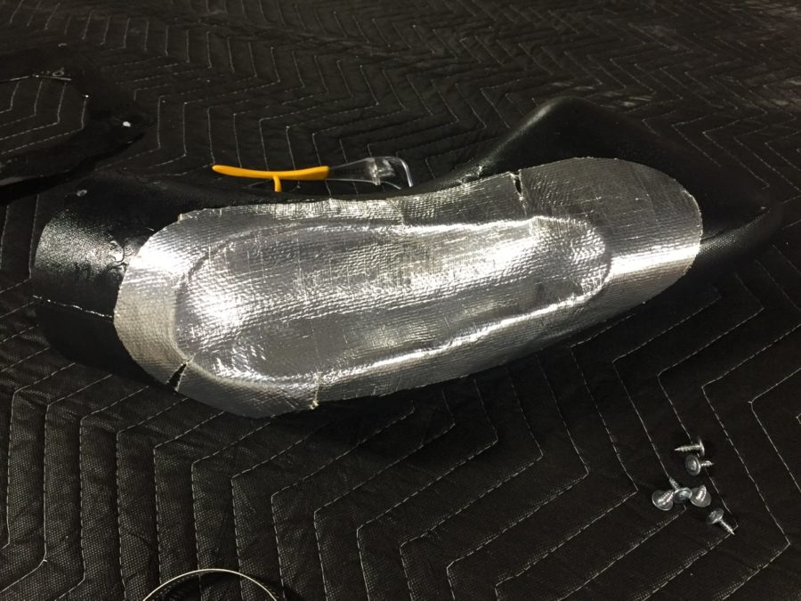
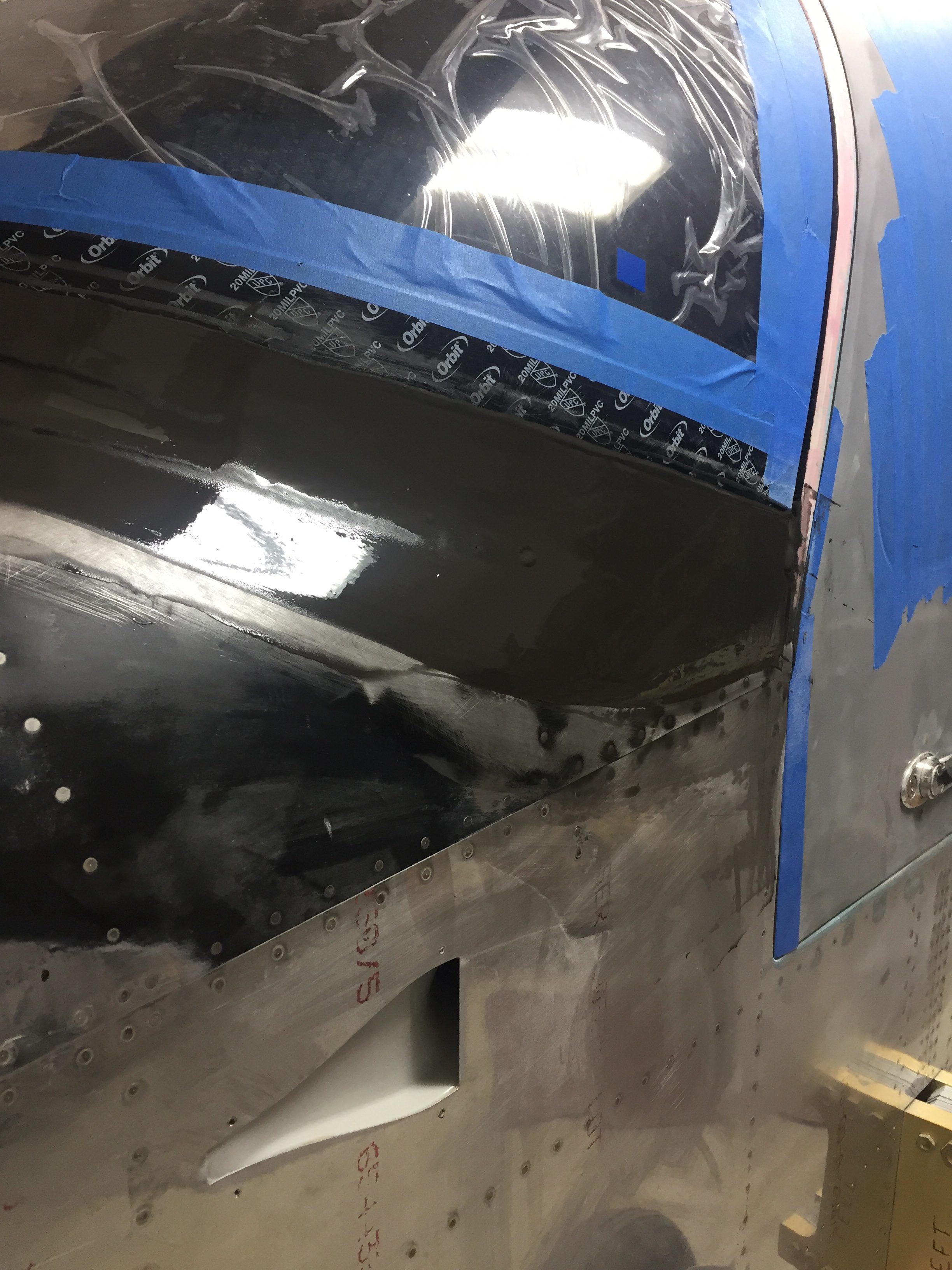
I had to notch out a few spots to create clearance around the compressor and mounting bracket.  Once I had the areas trimmed away and fit properly, I laid up fiberglass by hand to enclose the reliefs.  I debated on creating a mold or plug type thing but determined it’d be next to impossible for me since I’m not good at it anyway.  Plus I tried one of them and was pretty happy with the results, so why make it more complicated?  I did two layers of glass then a third on the inside.  I honestly don’t know what weight it was, but it’s very thin thus the three layers added up to about the same thickness as Show Planes had with the same rigidity.

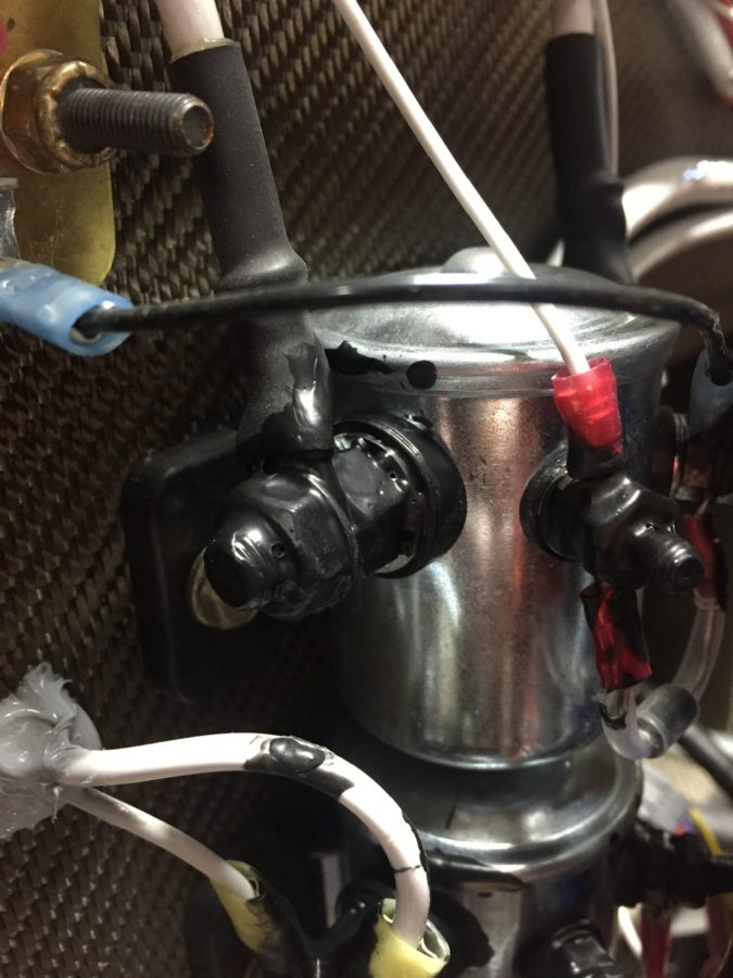
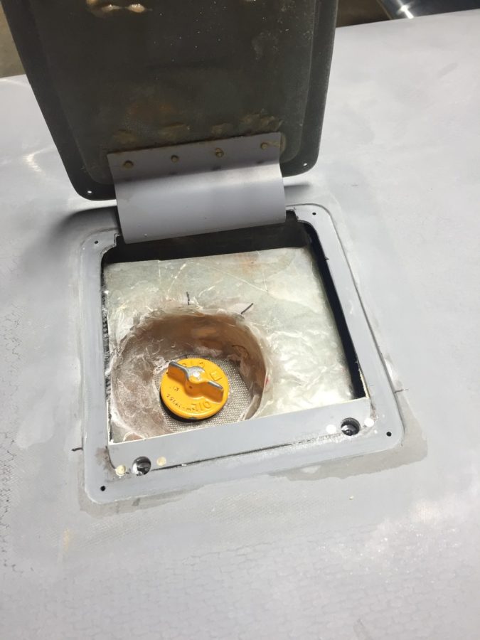
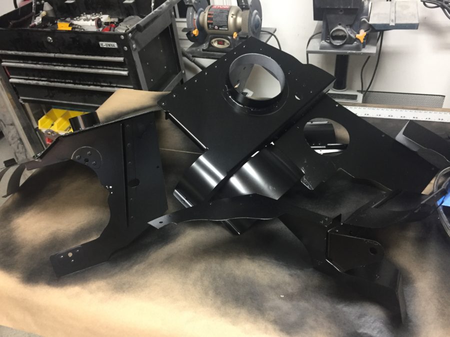
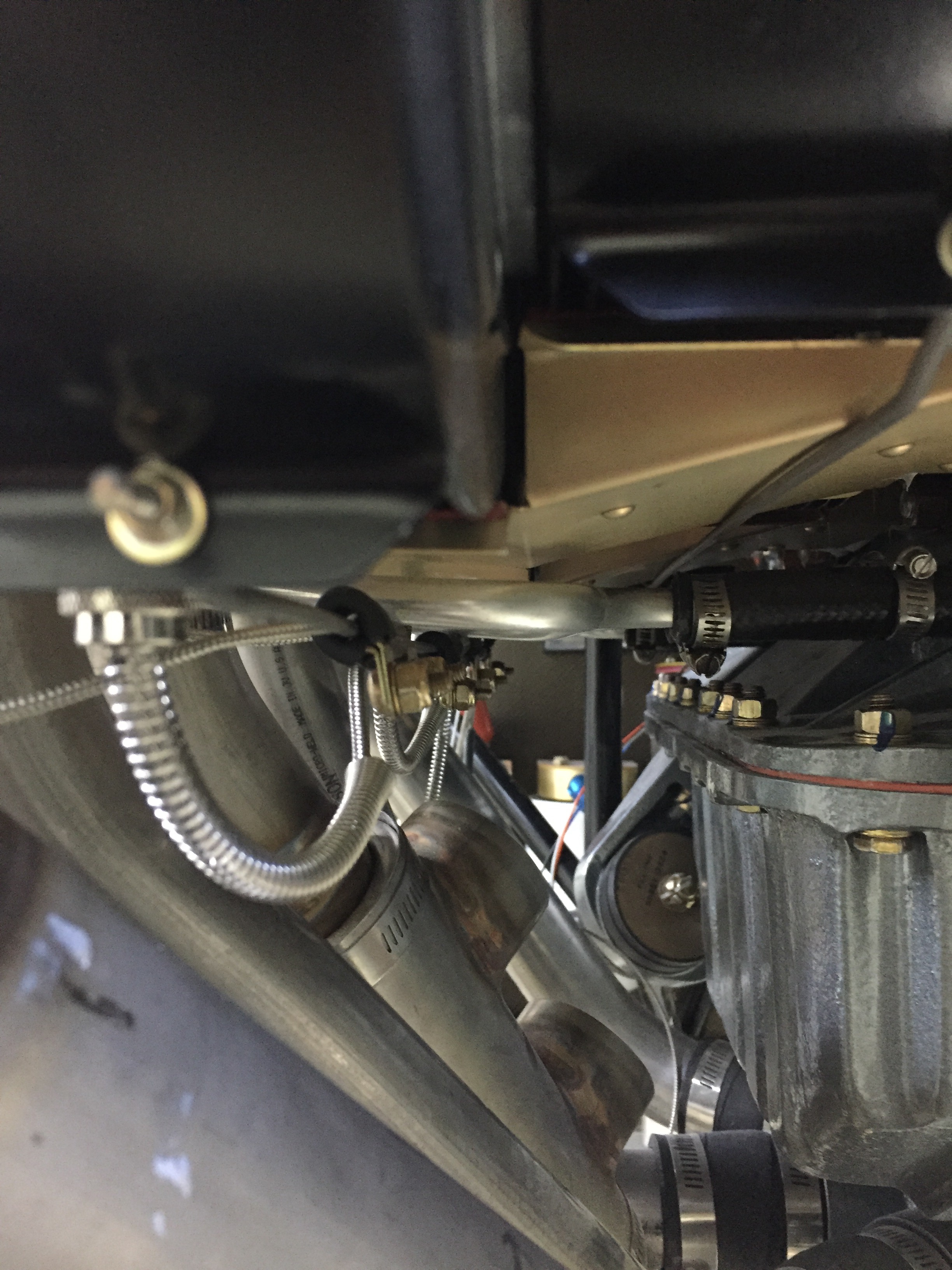
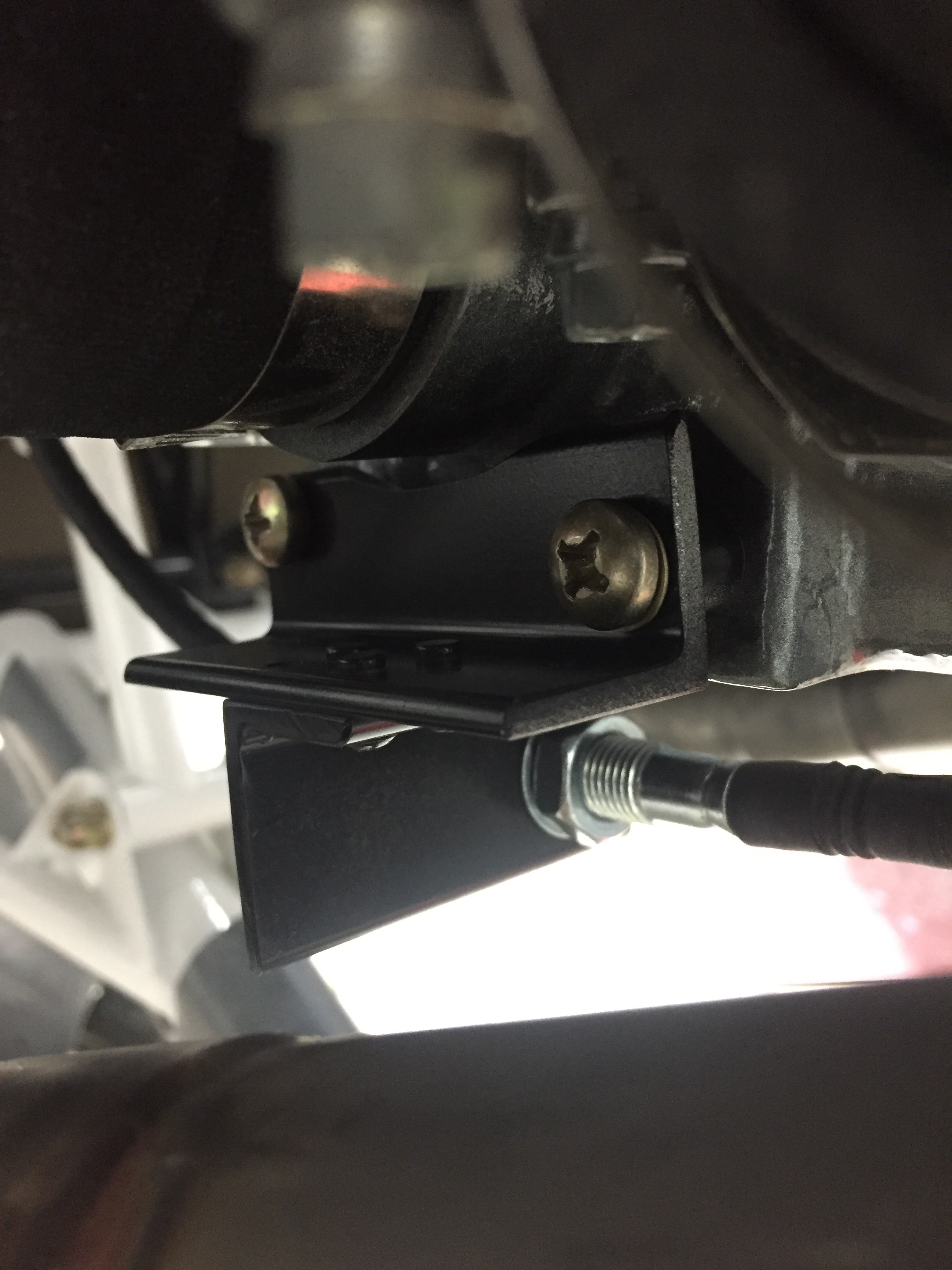
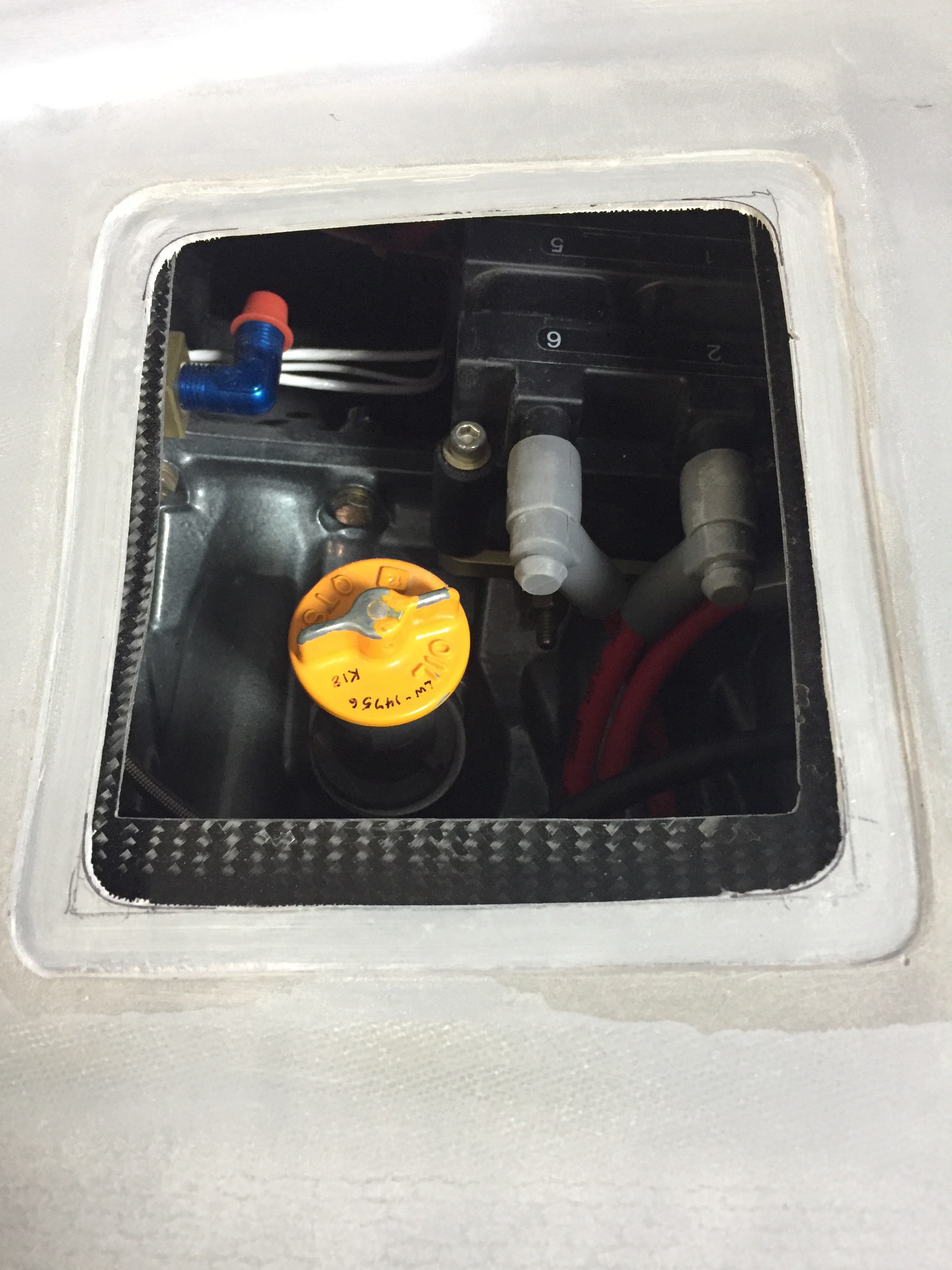
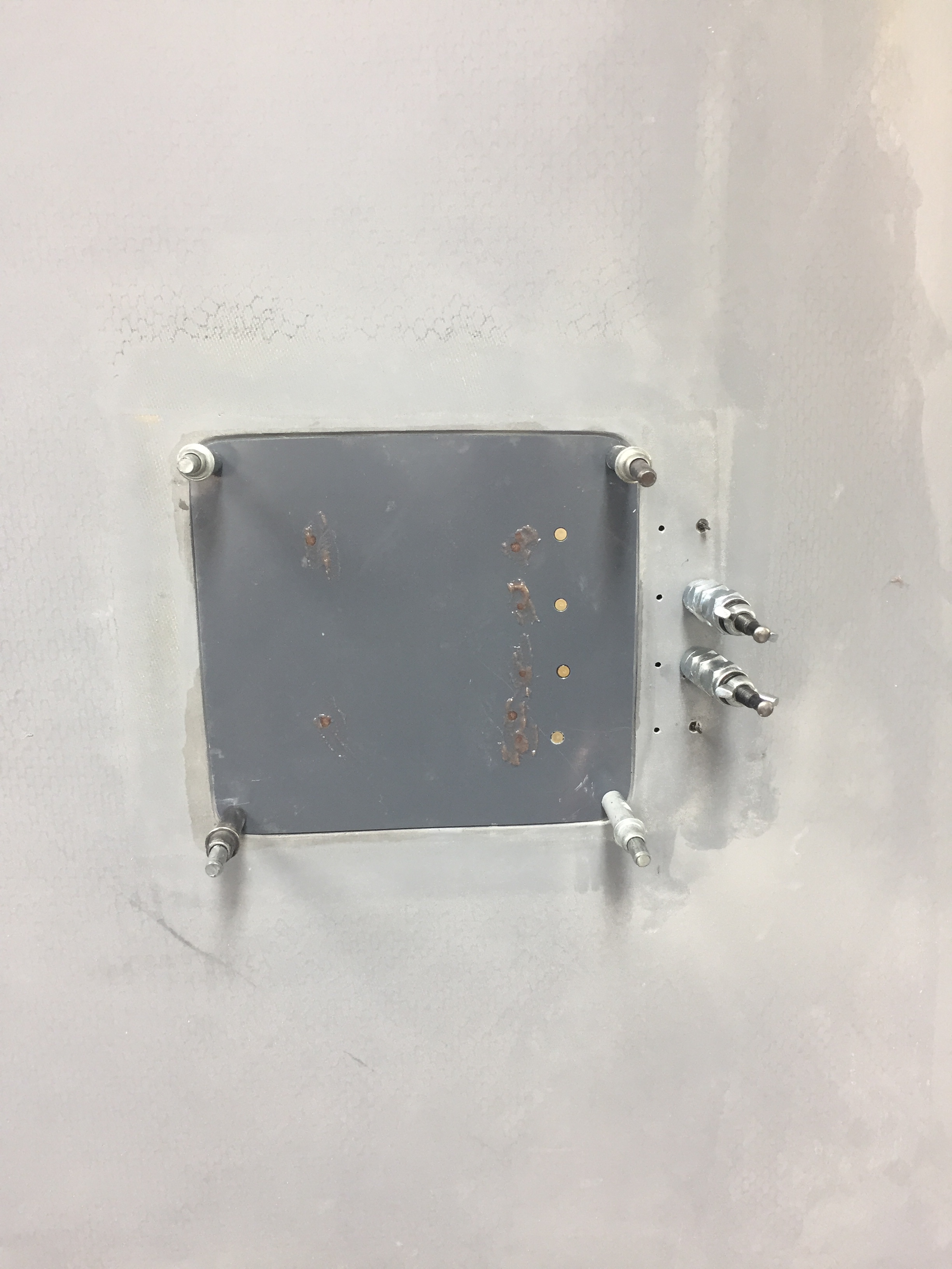
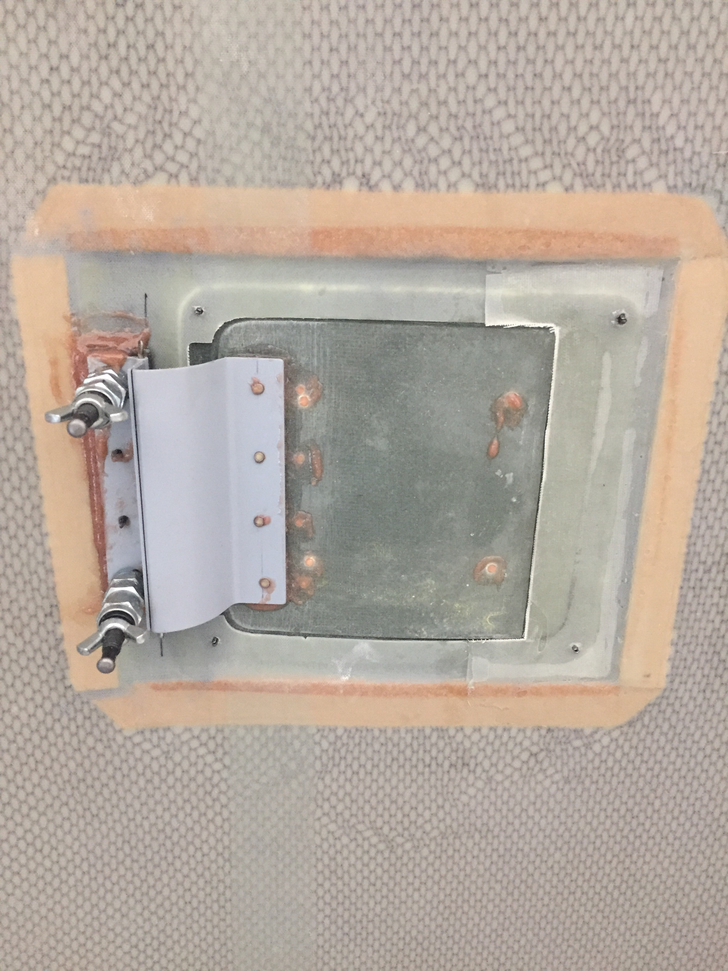
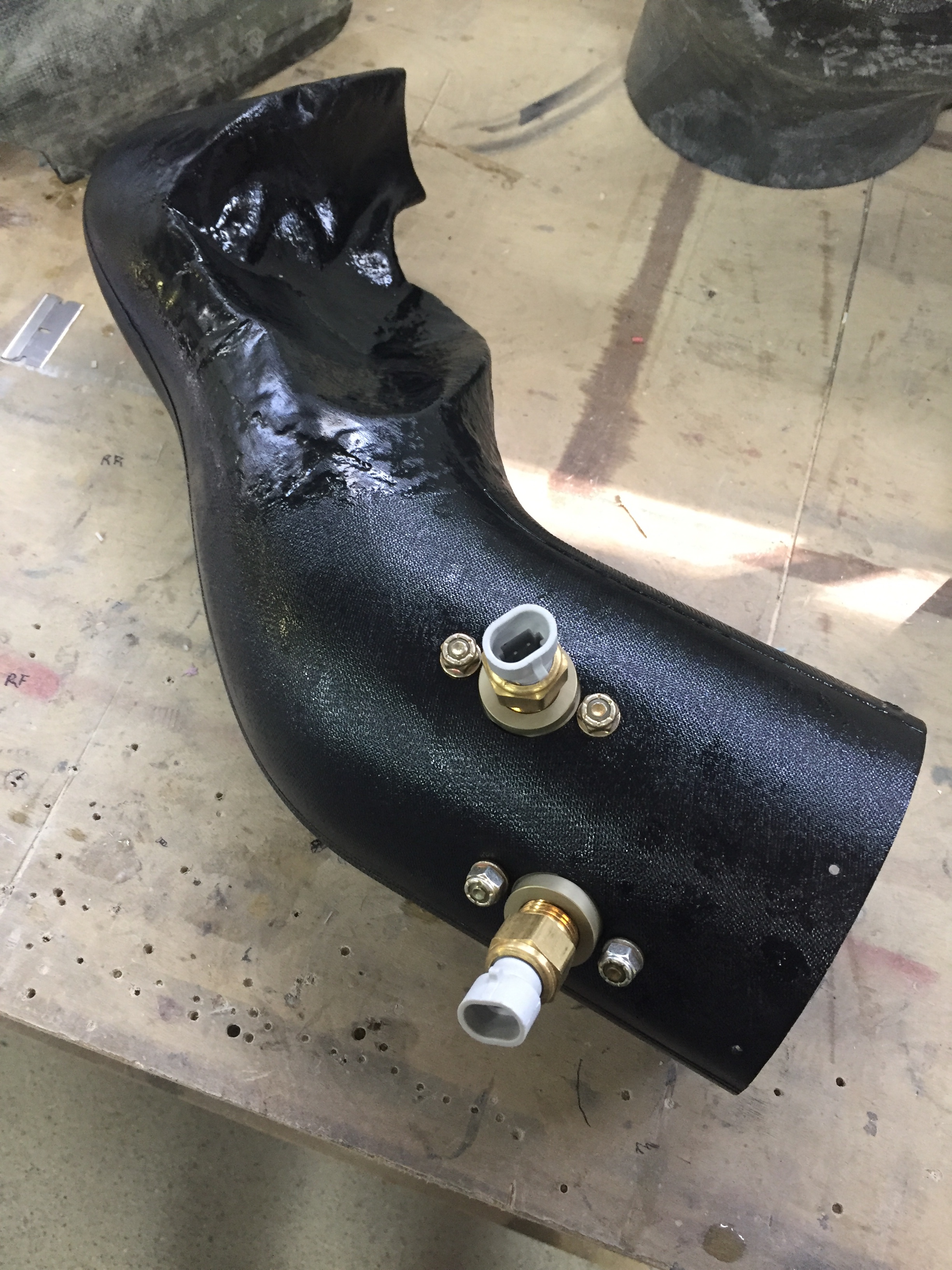
A bit of sanding and trimming, and everything with the ducts were finished up.  I painted them black just to hide them inside the cowling a bit and because I wanted to.  The last two sensors to install for the engine are intake temperature sensors that I had mocked up and ran wire to but not yet permenantly installed.  I bolted those on and sealed them with RTV to avoid air pressure loss.  I also drilled the required water drain holes just below the air filters at the lowest part of the intakes.

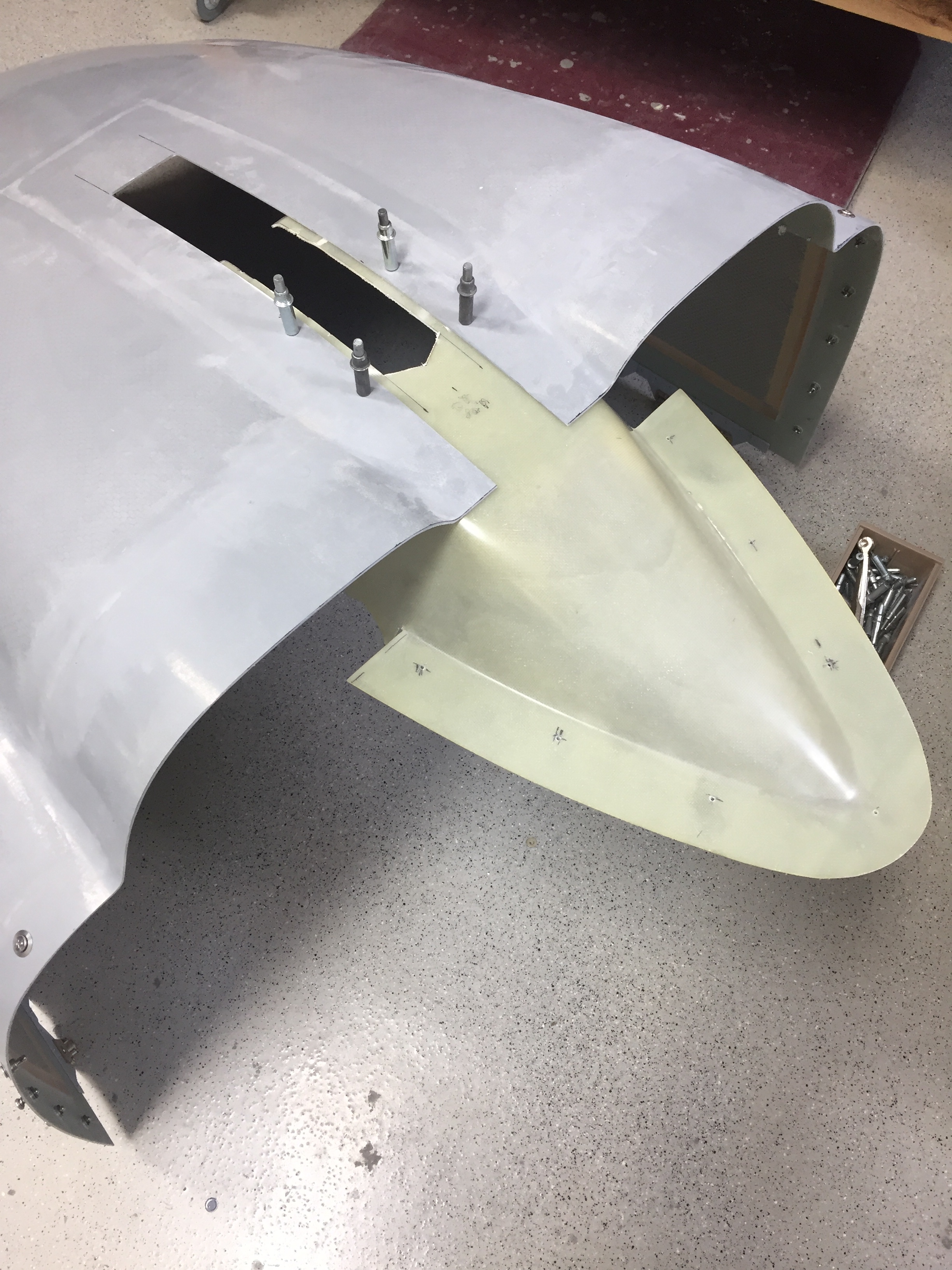
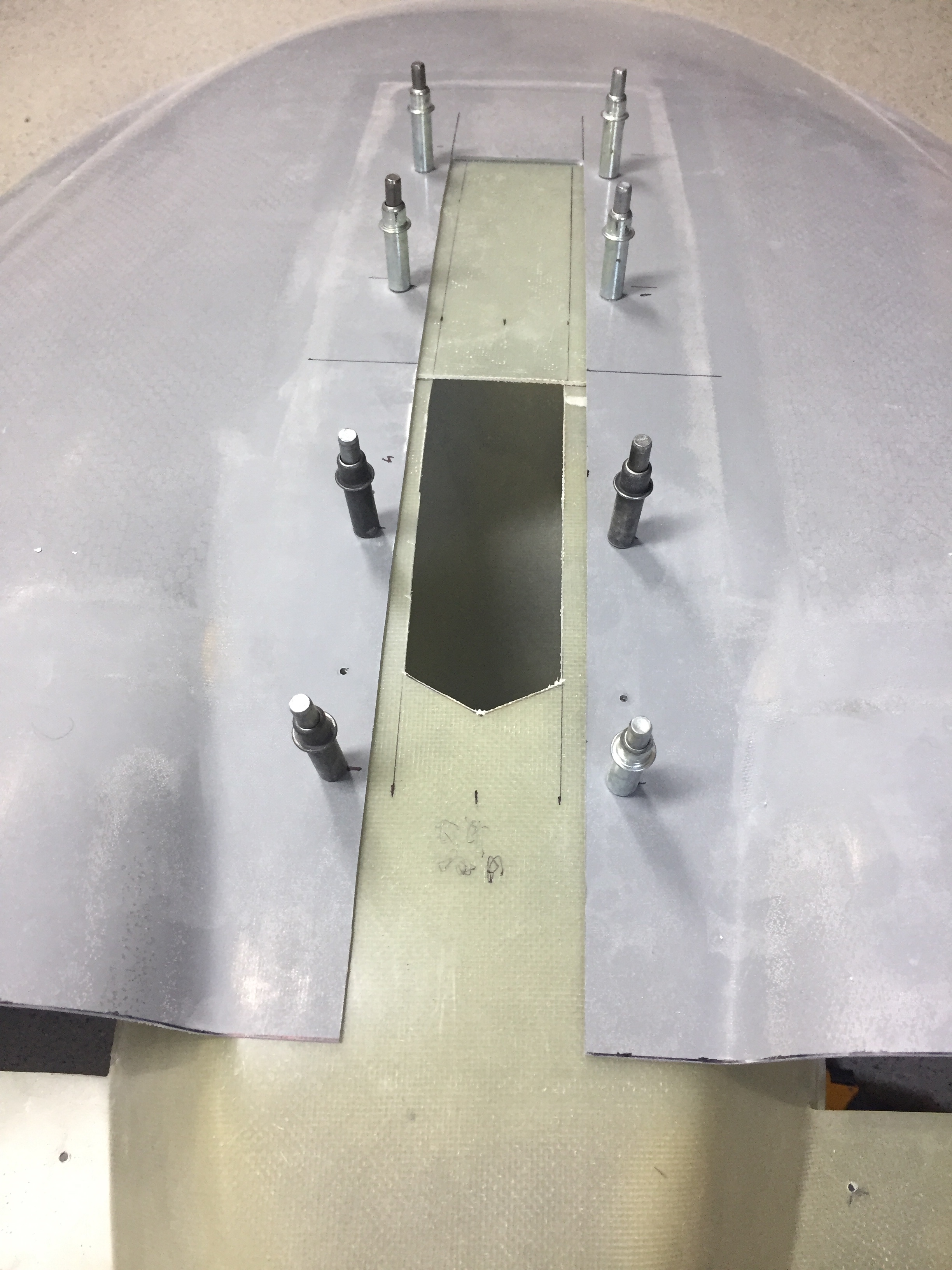
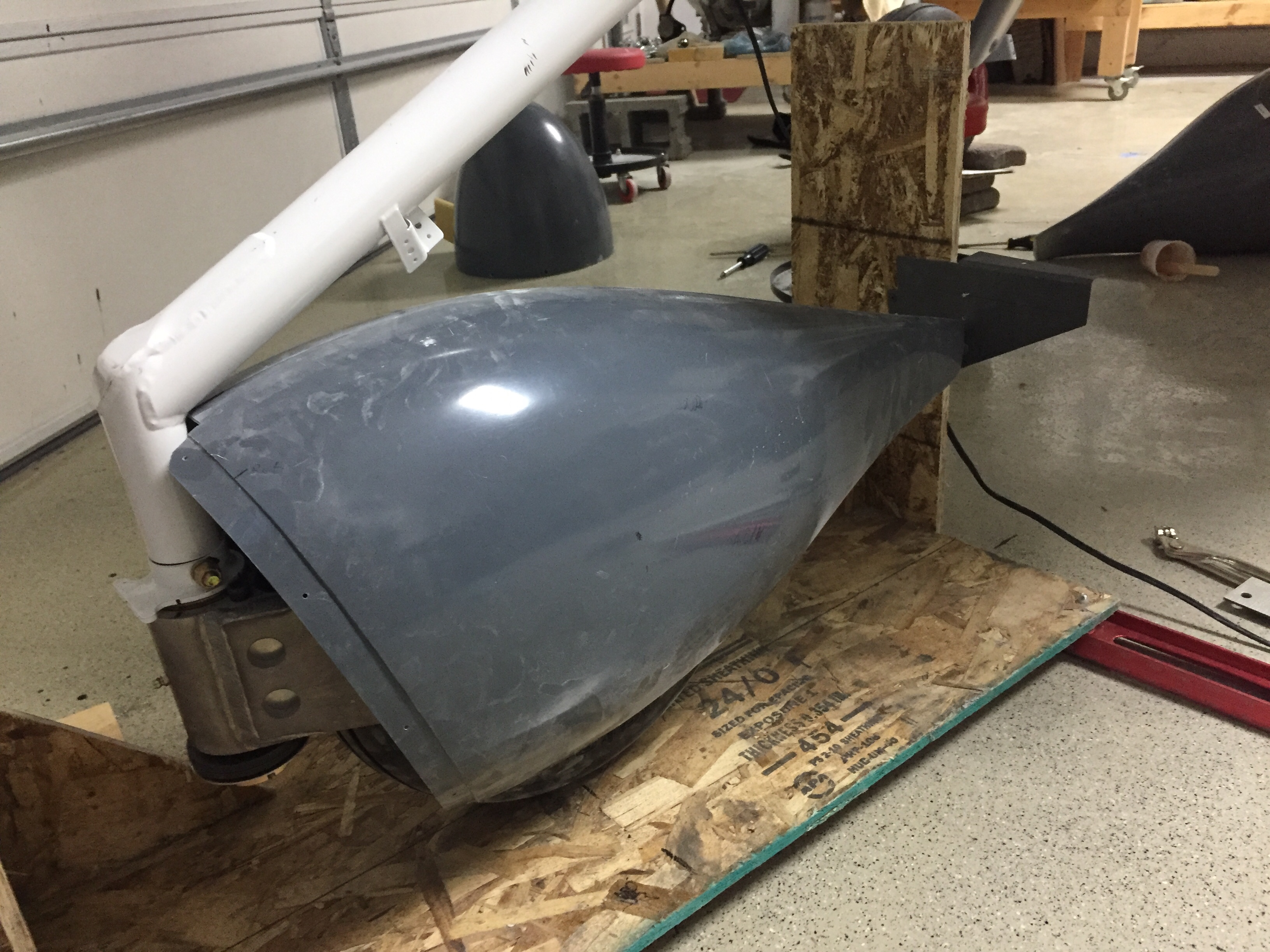
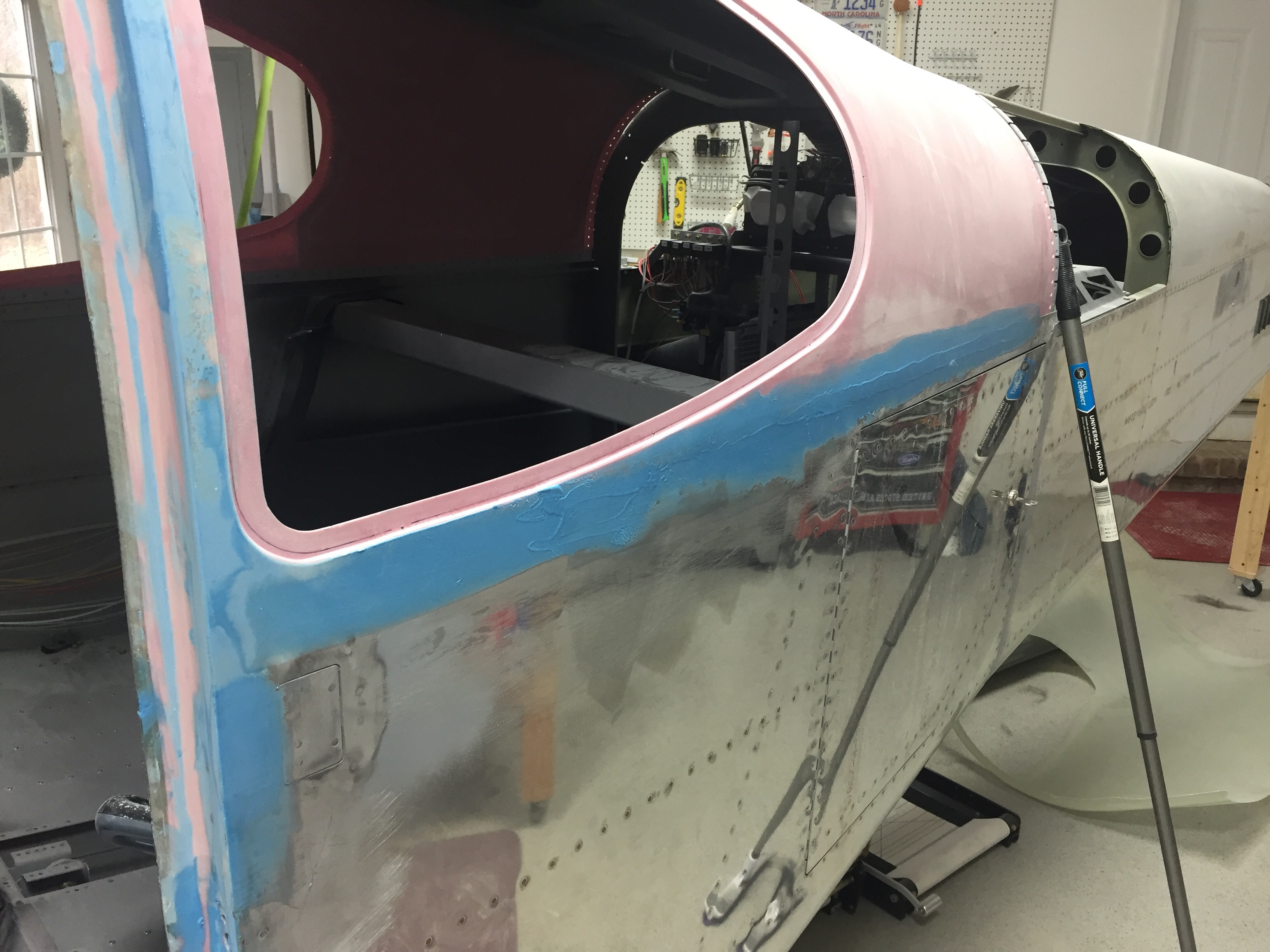
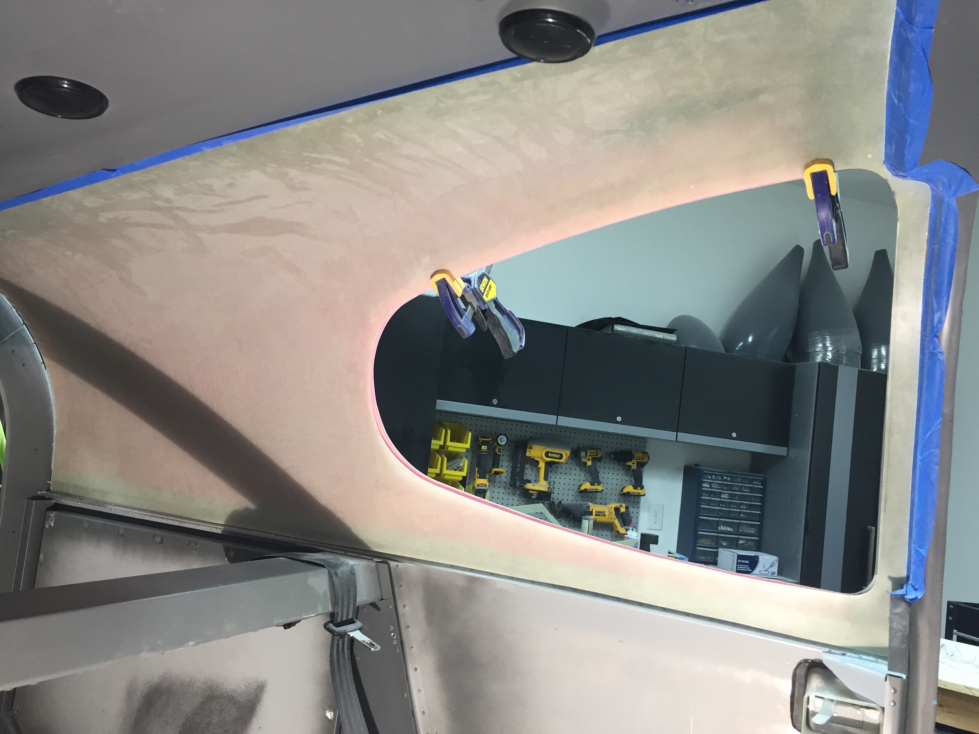
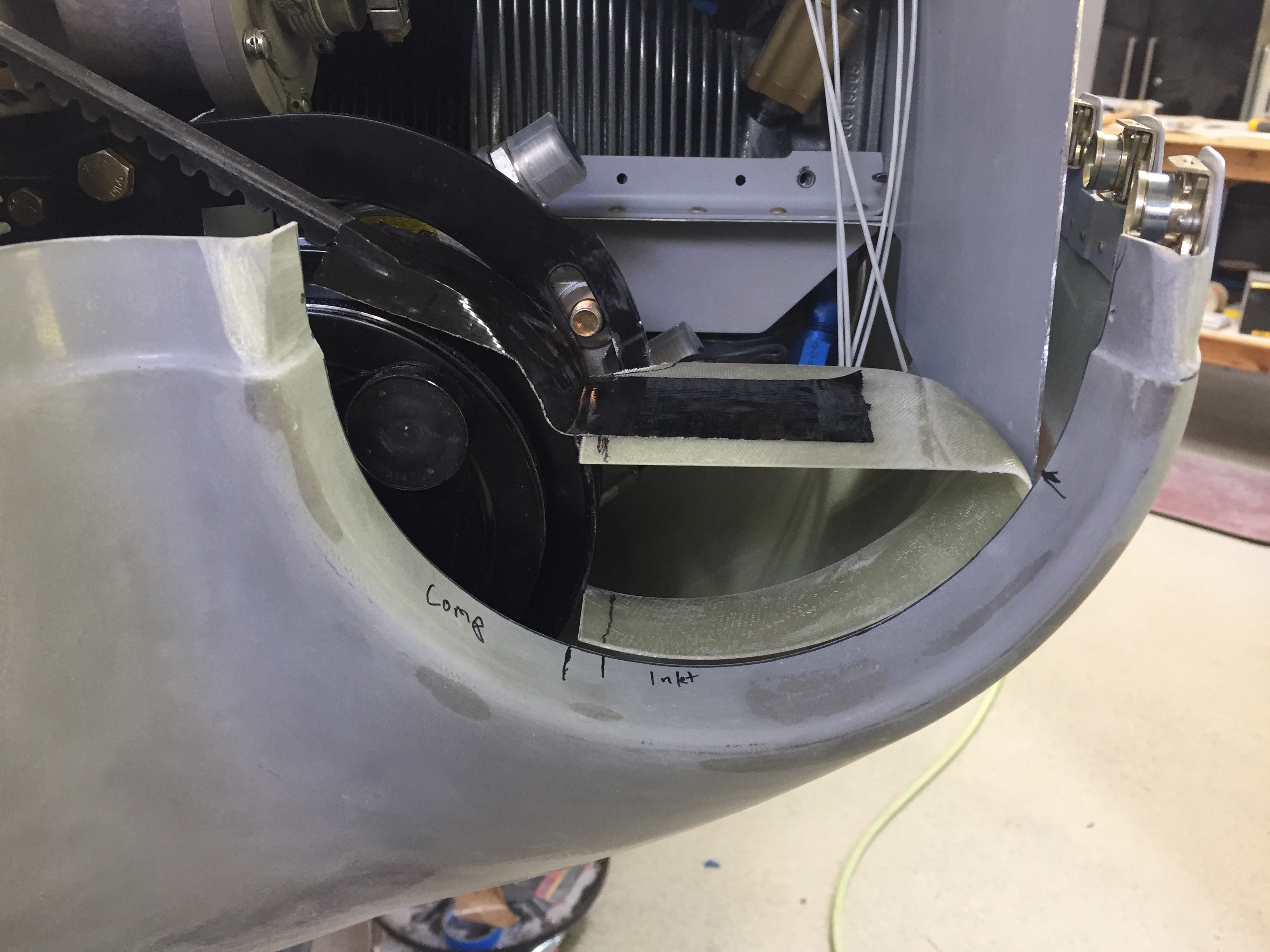
It all sounds so simple now, but trust me, I spent many hours thinking, debating, looking, thinking some more, and finally working out the fit of the ducts and getting a solution that I am happy with.  These were just a warm up for the cooling ducts!  Show Planes have you modify the stock baffle ramps and provide upper cowling ramps to be epoxied to the cowl to help guide airflow into the engine baffles.  Since I am using the plenum, I need to keep air going from the openings to under the plenum.  I had originally invisioned carving foam and creating a mold, but once I got busy working, carving foam was going to be next to rediculously impossible.  It’d take me weeks just to do the molds.  So, I took another approach, use what I had on hand and don’t reinvent the wheel.

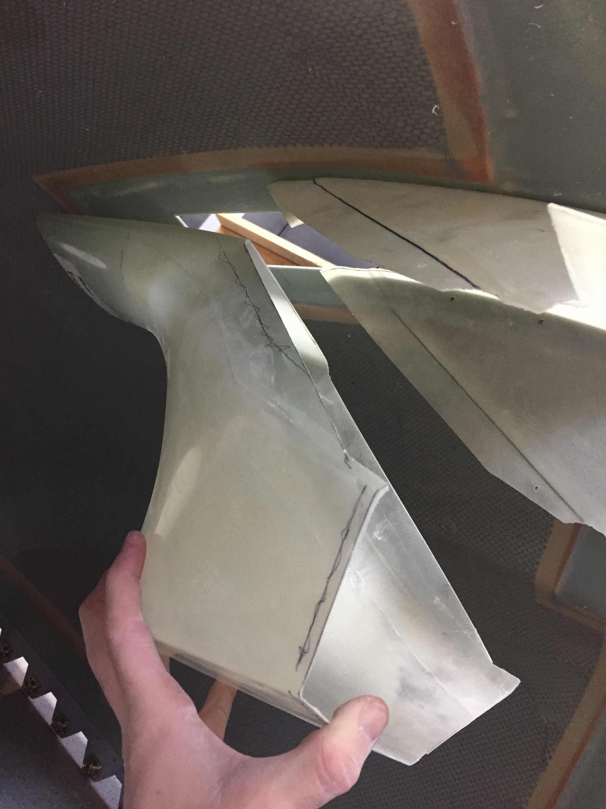
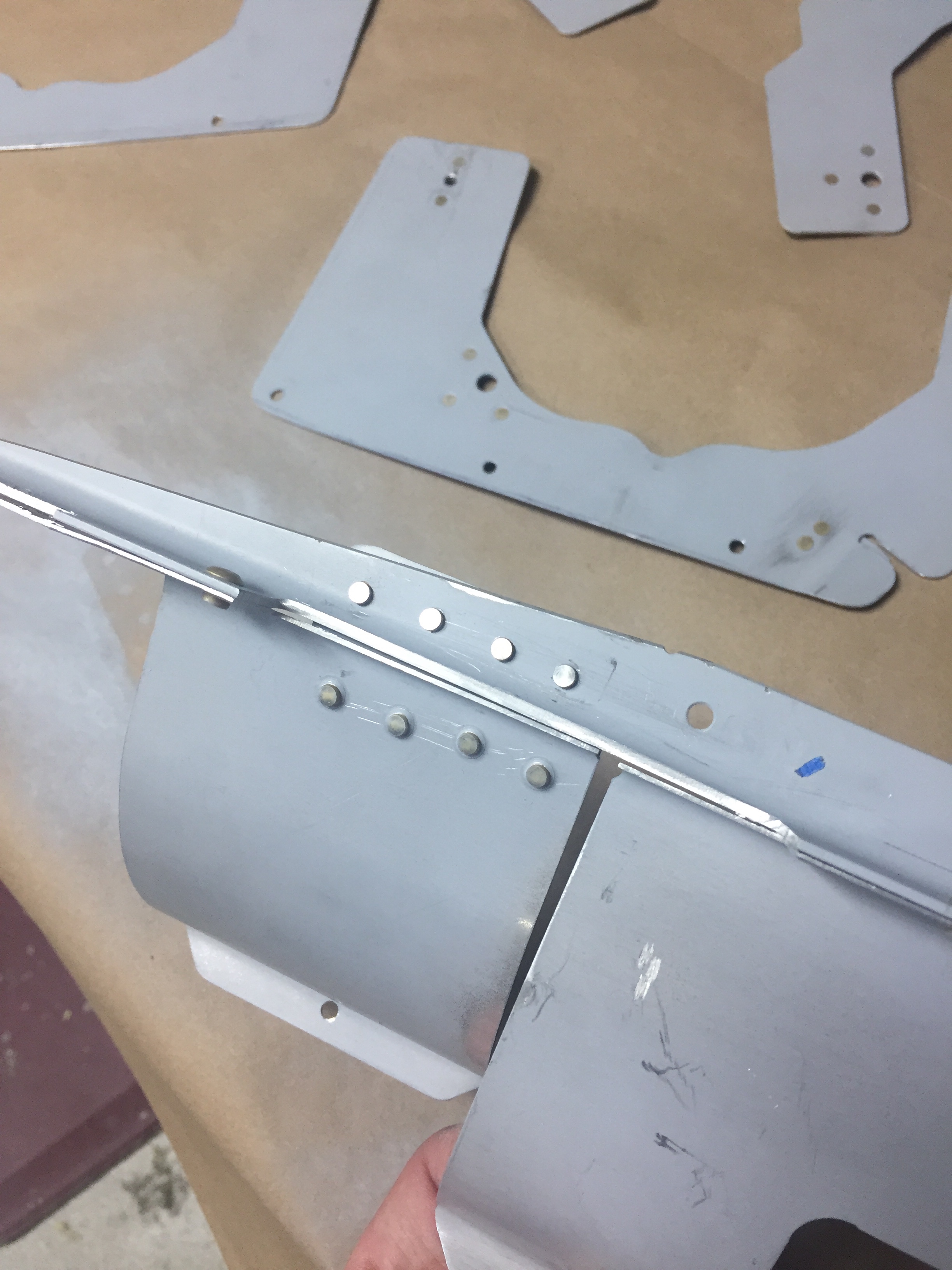
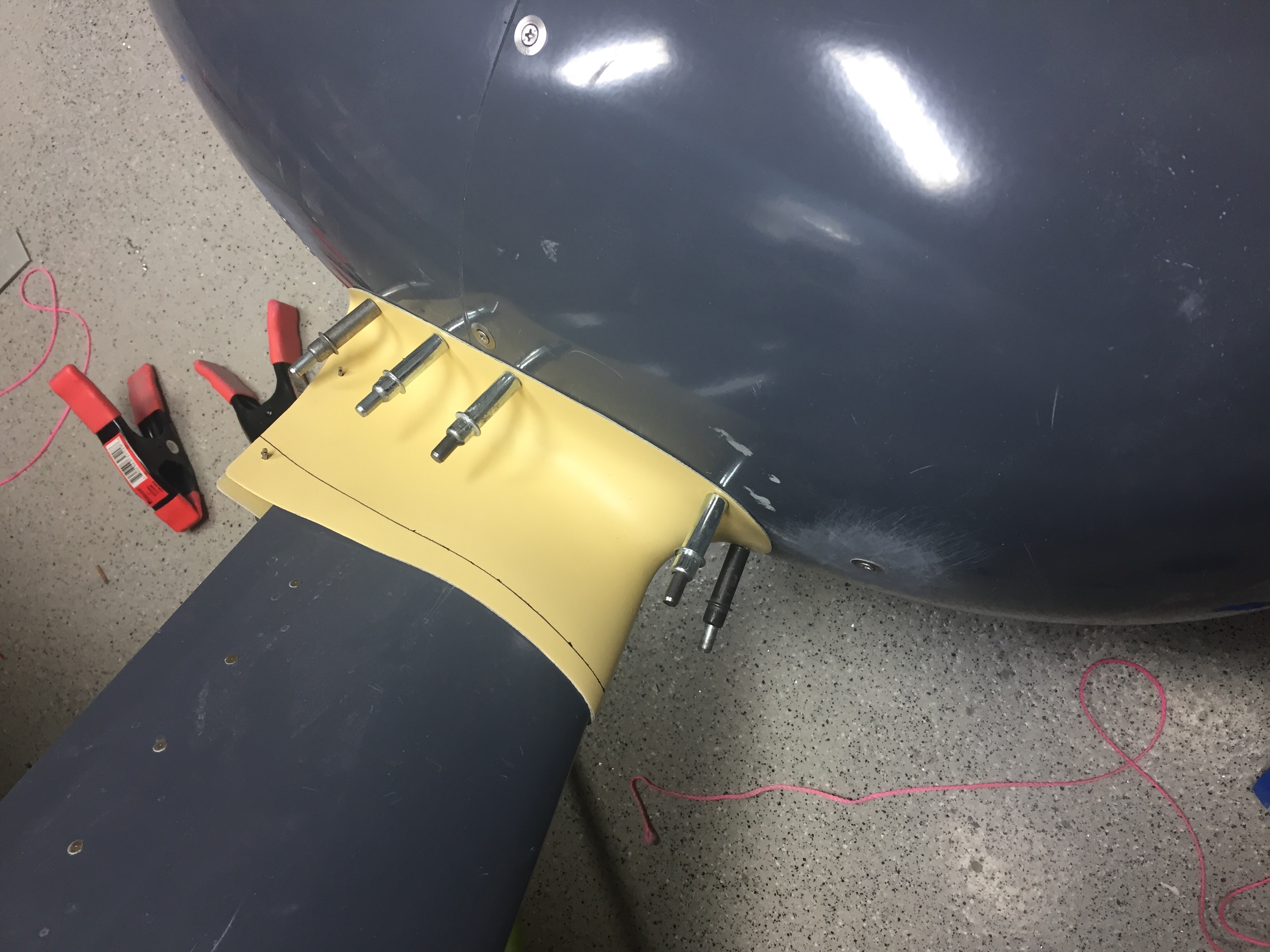
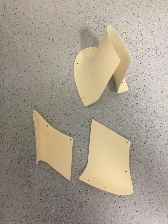
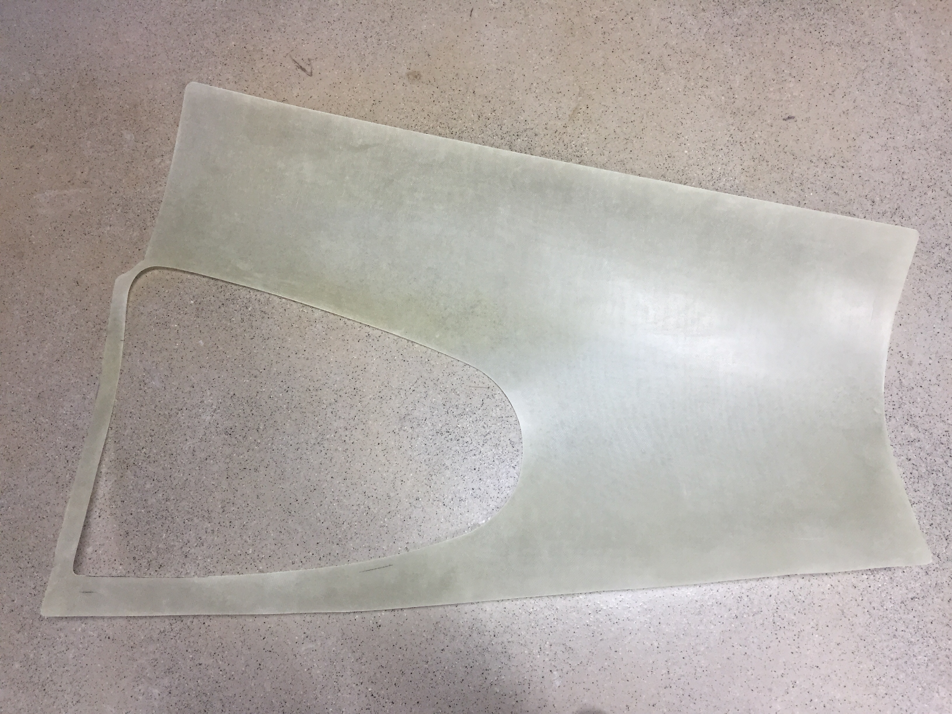
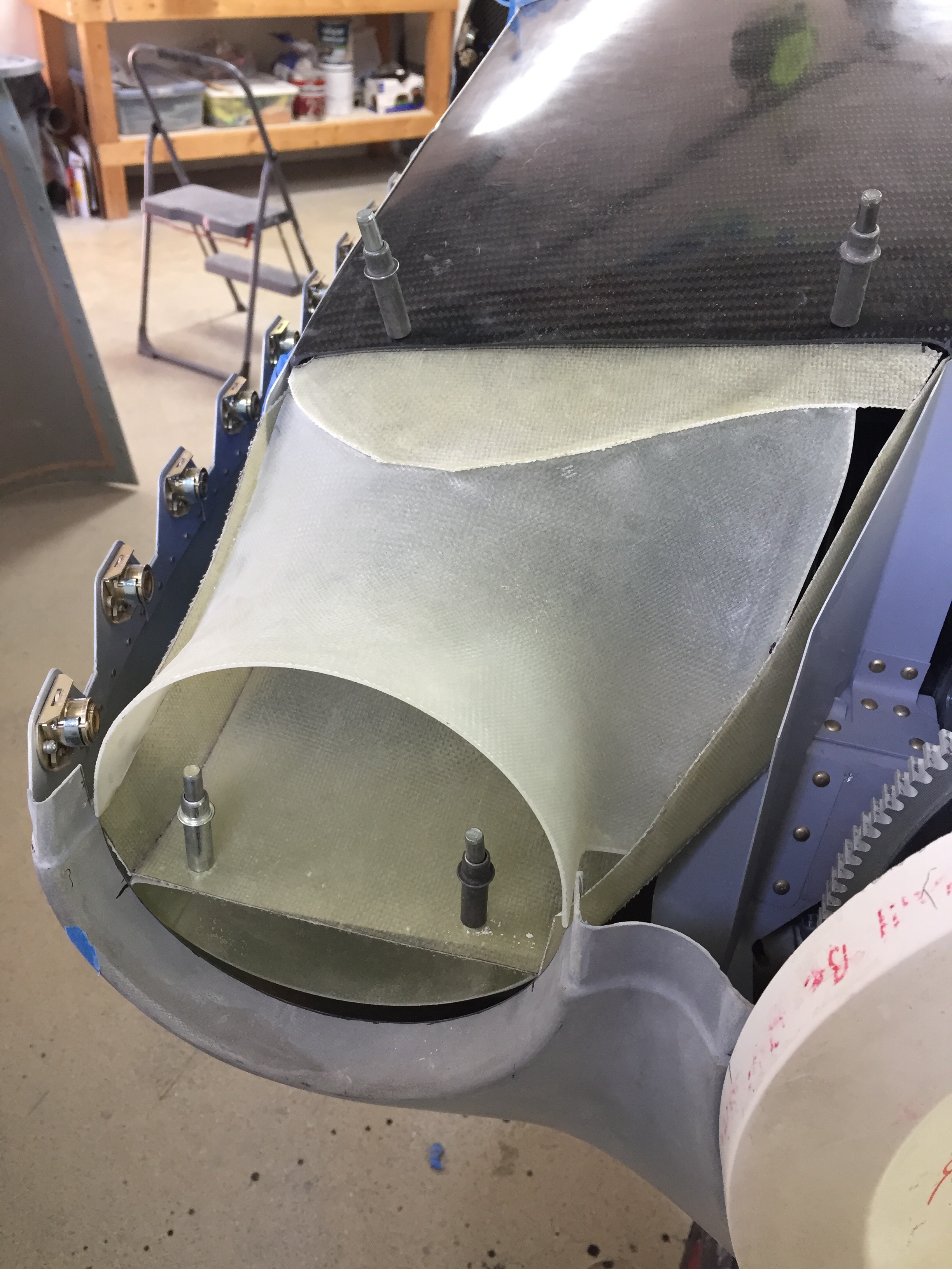
The upper ramps from Show Planes are the same size as the openings, so I started with those as a transition to the plenum.  Part of the kit is some thin flatstock fiberglass that I wound up using to create the cooling ducts.  I used some manilla folders to create templates and basically pieced it all together using the fiberglass and super glue.  Starting on the right side was simple, as there is no modifications needed and it’s a much simpler routing for air to enter the plenum covered area.

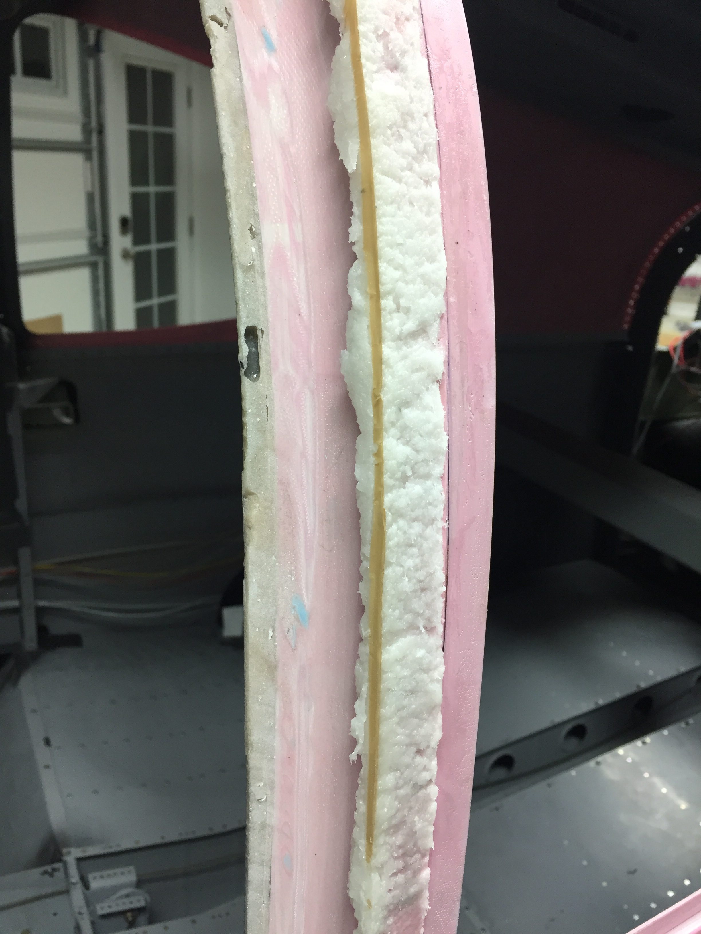
Again, I figured I’d use this rough build up as a mold to create a sleek curvy, sexy, duct that would look like it came from a Formula 1 team.  So I got a brilliant idea of filling it with blocks of foam and then using spray foam out of a can to fill in the gaps.  I’d then sand, trim, and shape before using it as a mold.  Well guess how that worked?  Not great, folks.  Not great.  I didn’t realize that spray foam has to be exposed to air to set up.  So me putting the duct in a plastic bag in a box resulted not in a nice firm square, but a grocery bag full of gooy sticky snot.

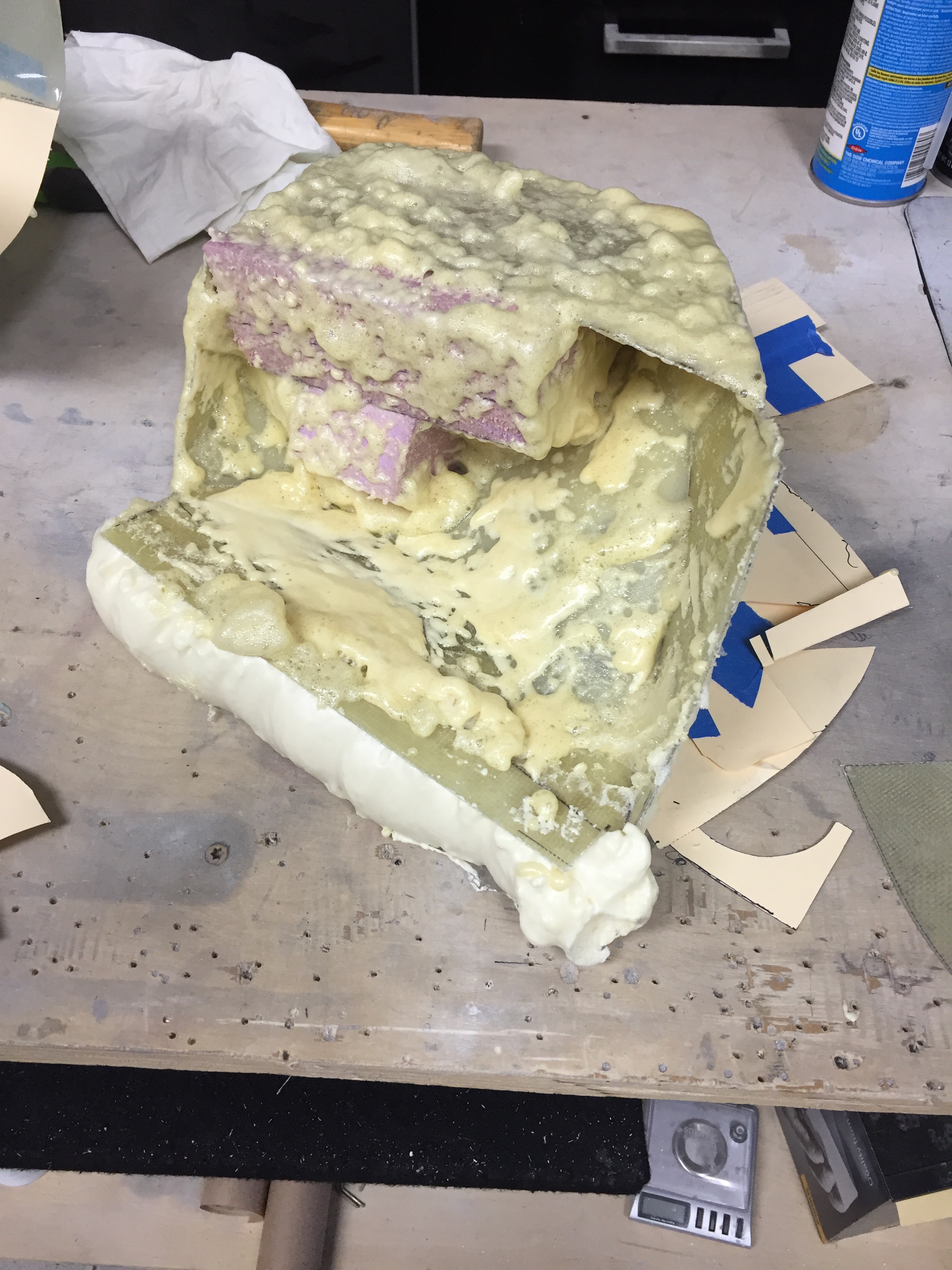
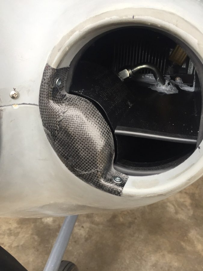
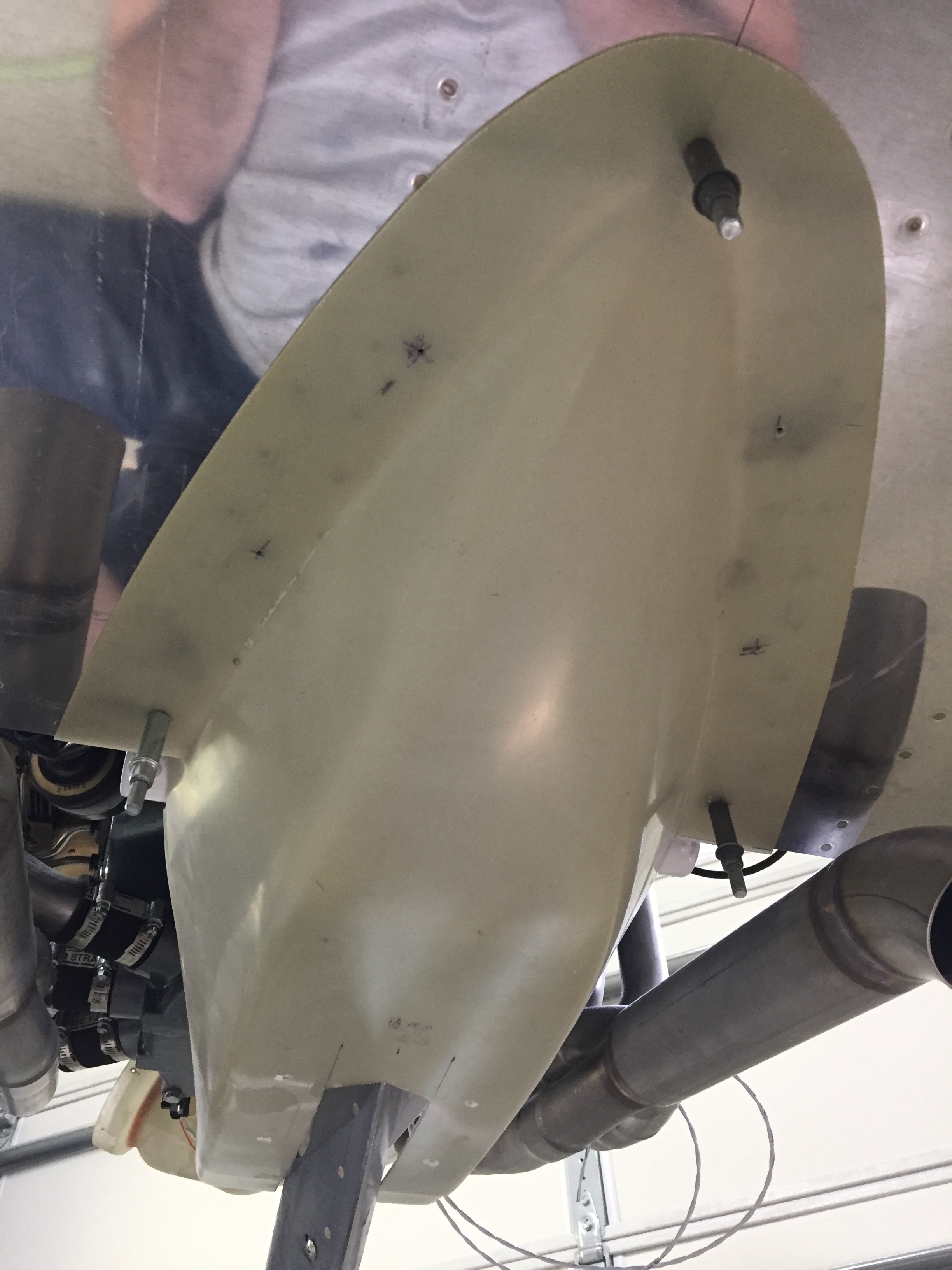
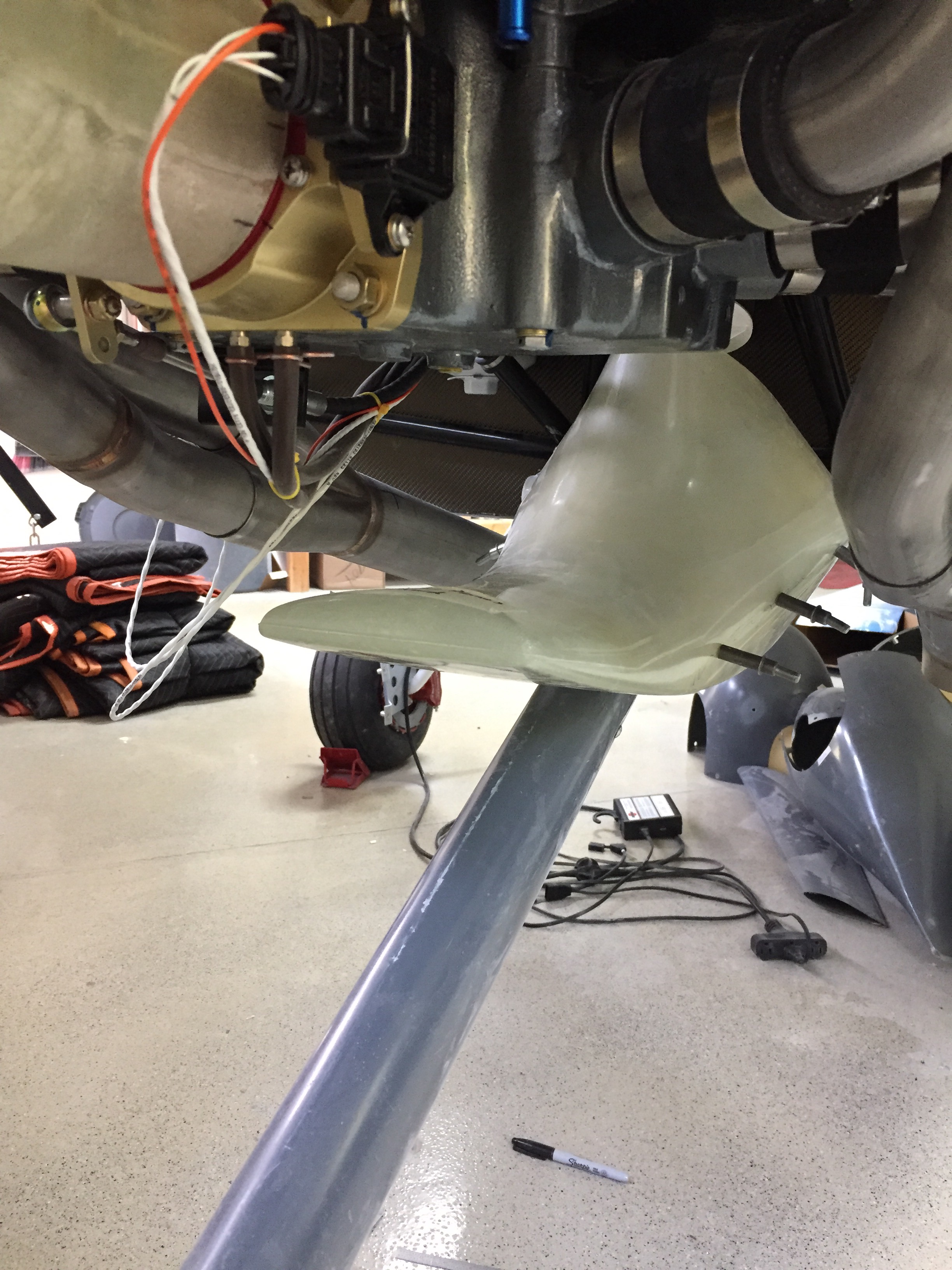
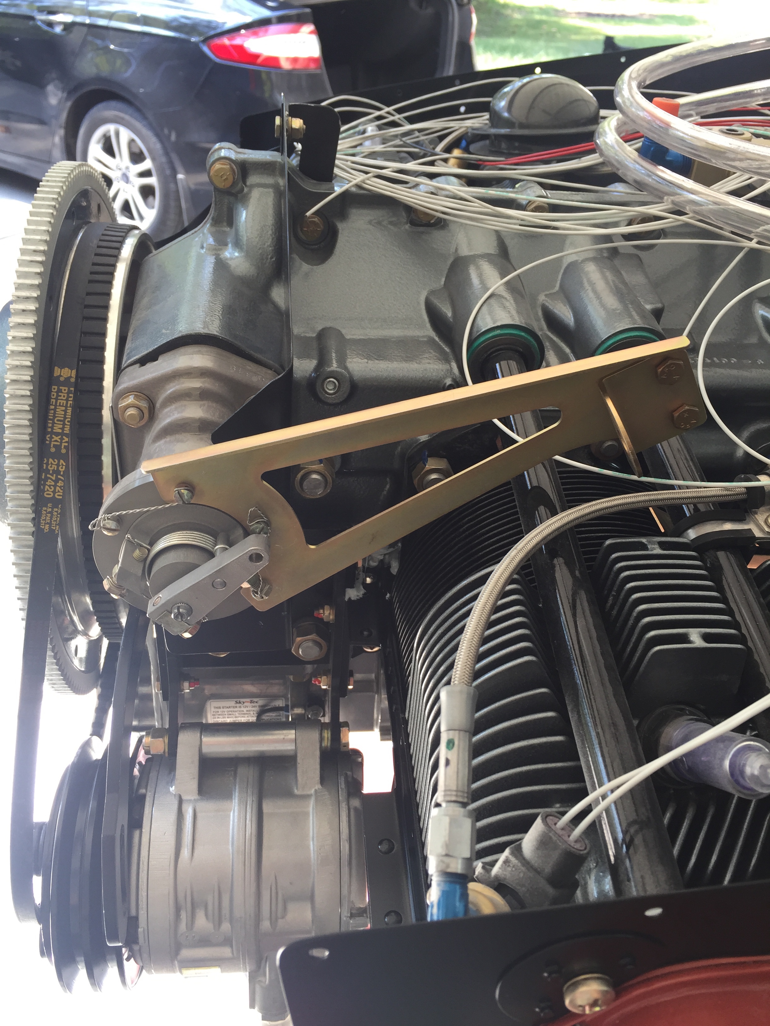
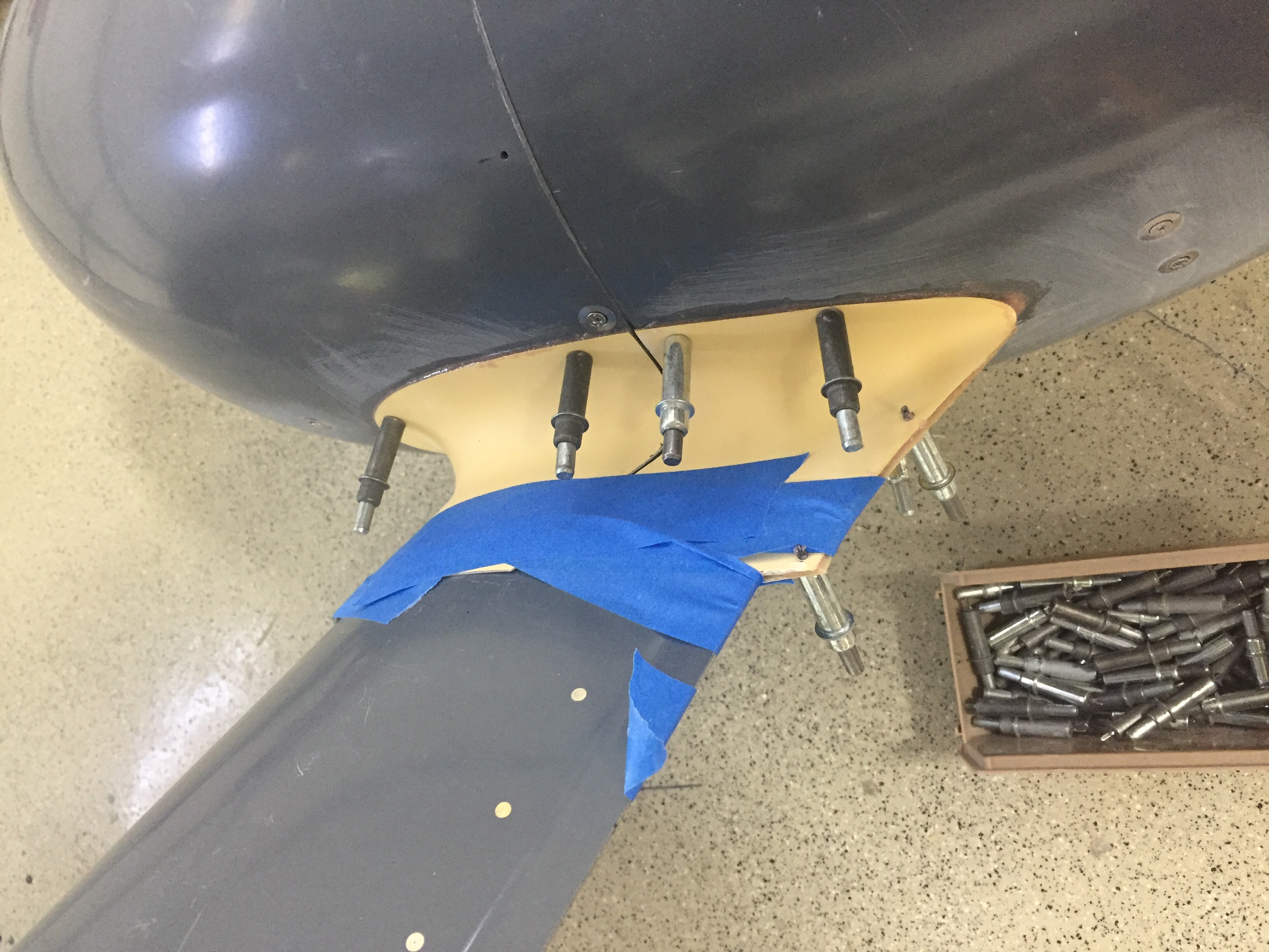
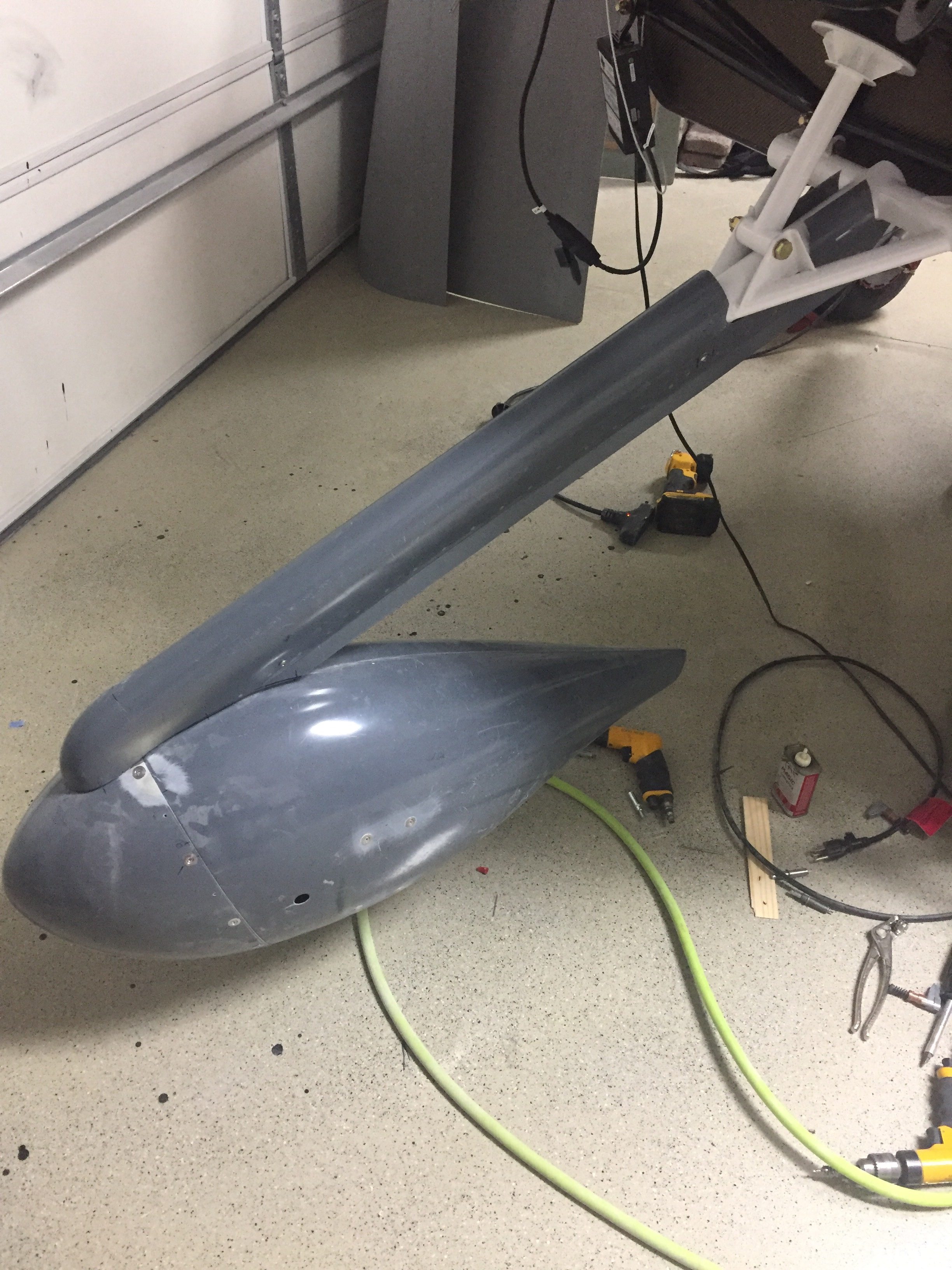
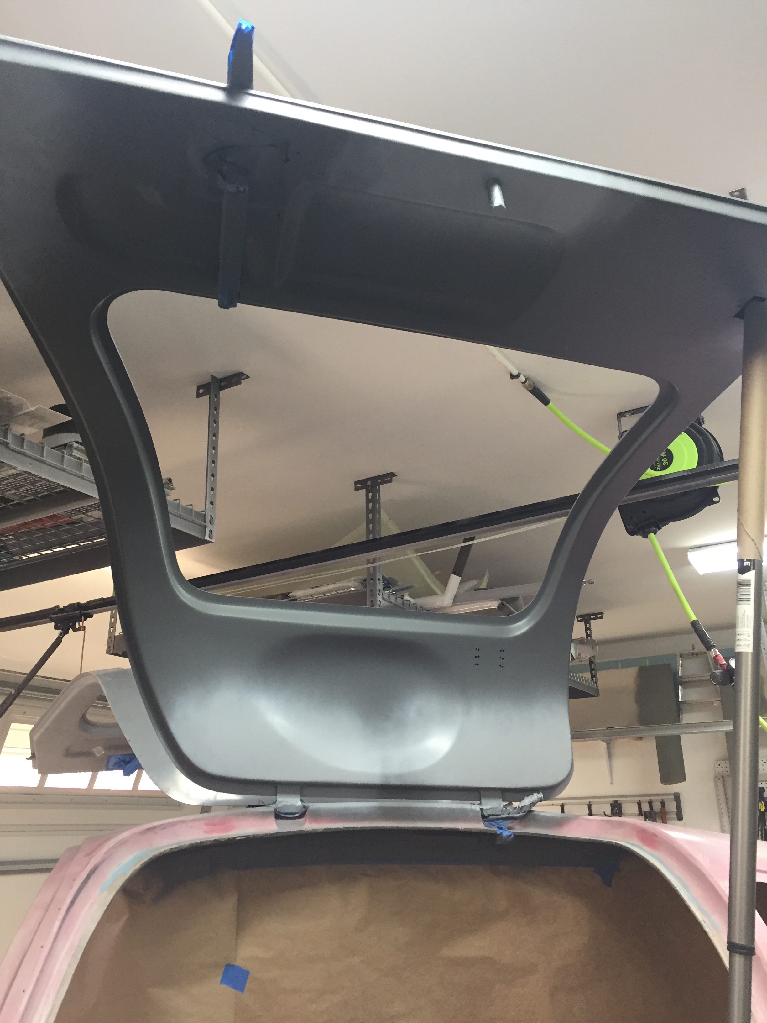
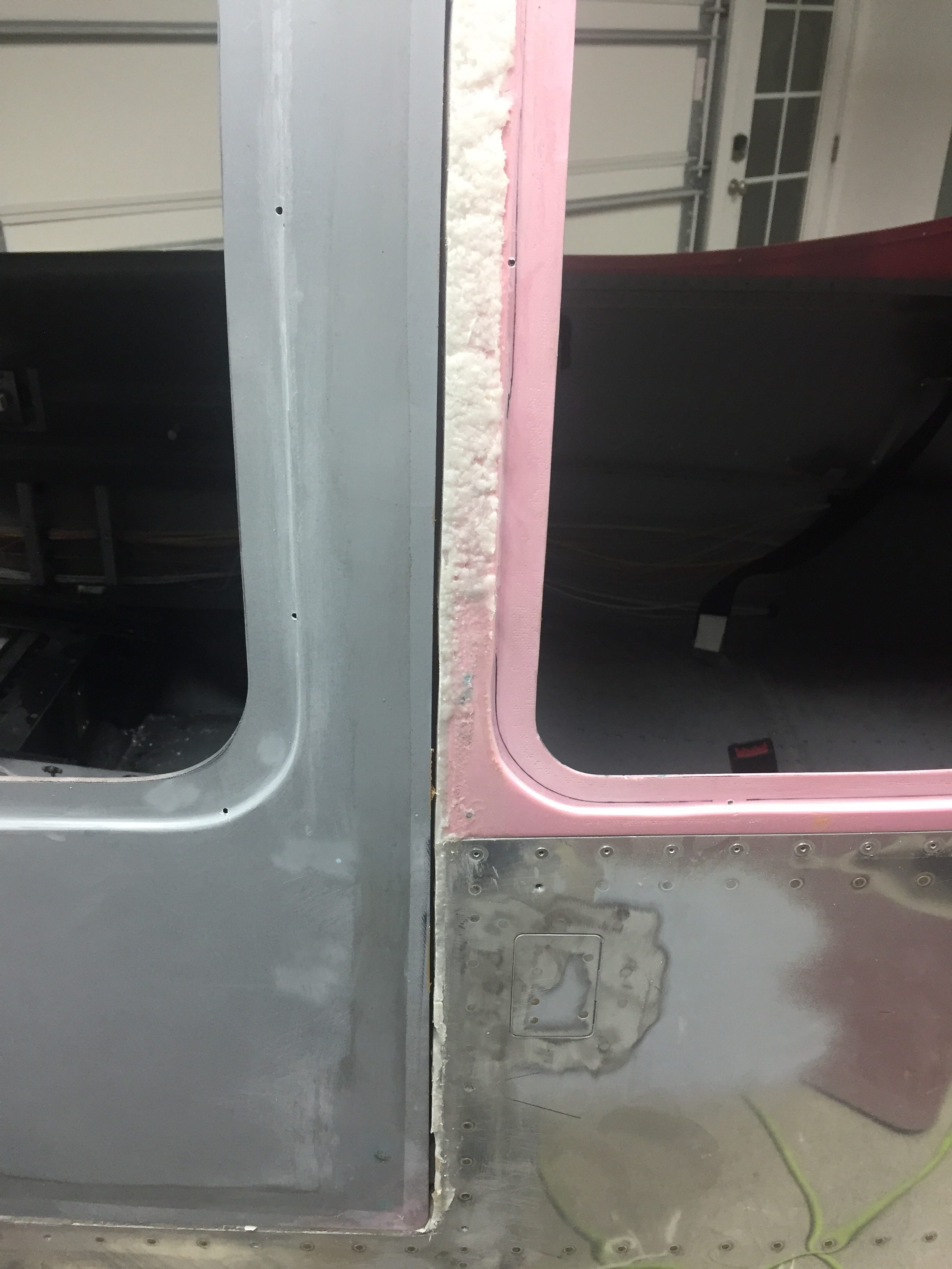
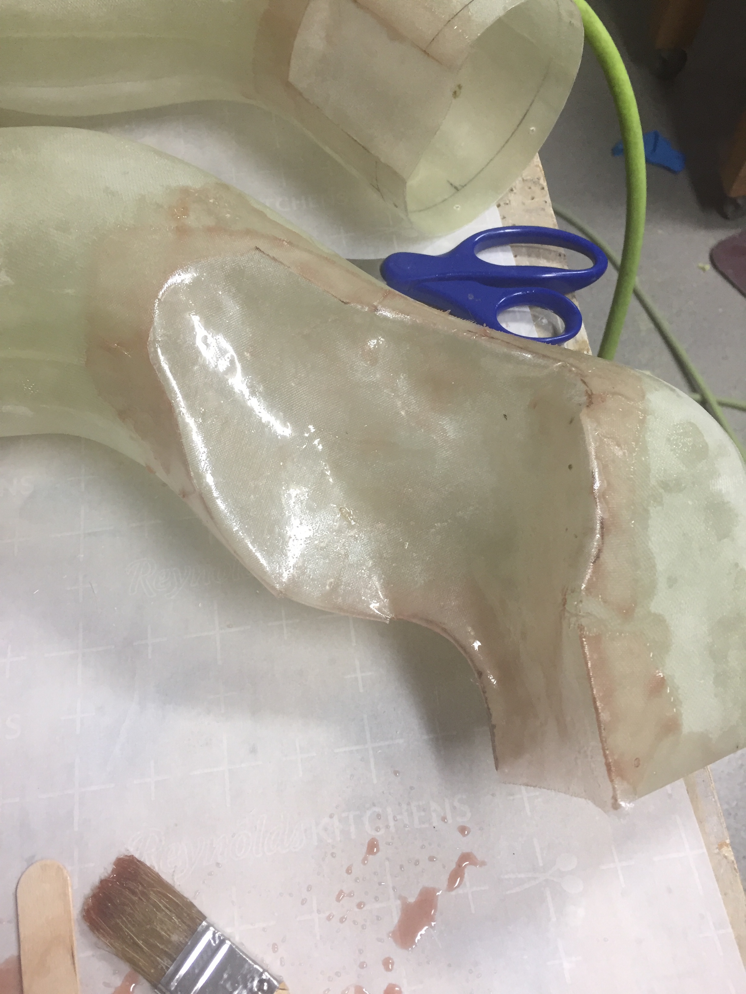
I then decided I’m making it difficult and should just keep it simple, stupid.  So I decided to stick with the original prototypes and just reinforce the joints and smoth as much as possible.  While I waited for the disaster to finish curing so I could clean all the foam back off, I started on the left duct.  This was much more complicated with the compressor in the way.  Not only do I need to get around the compressor, but also the tensioning arm and v-belt.  Finally, the prop governor is there too and oh, wait, I forgot, the refrigerant line from the compressor.  Again, I used manilla folders cut up as templates and just pieced it all together, maximizing the amount of space and using the upper ramp from Show Planes as the starting point.

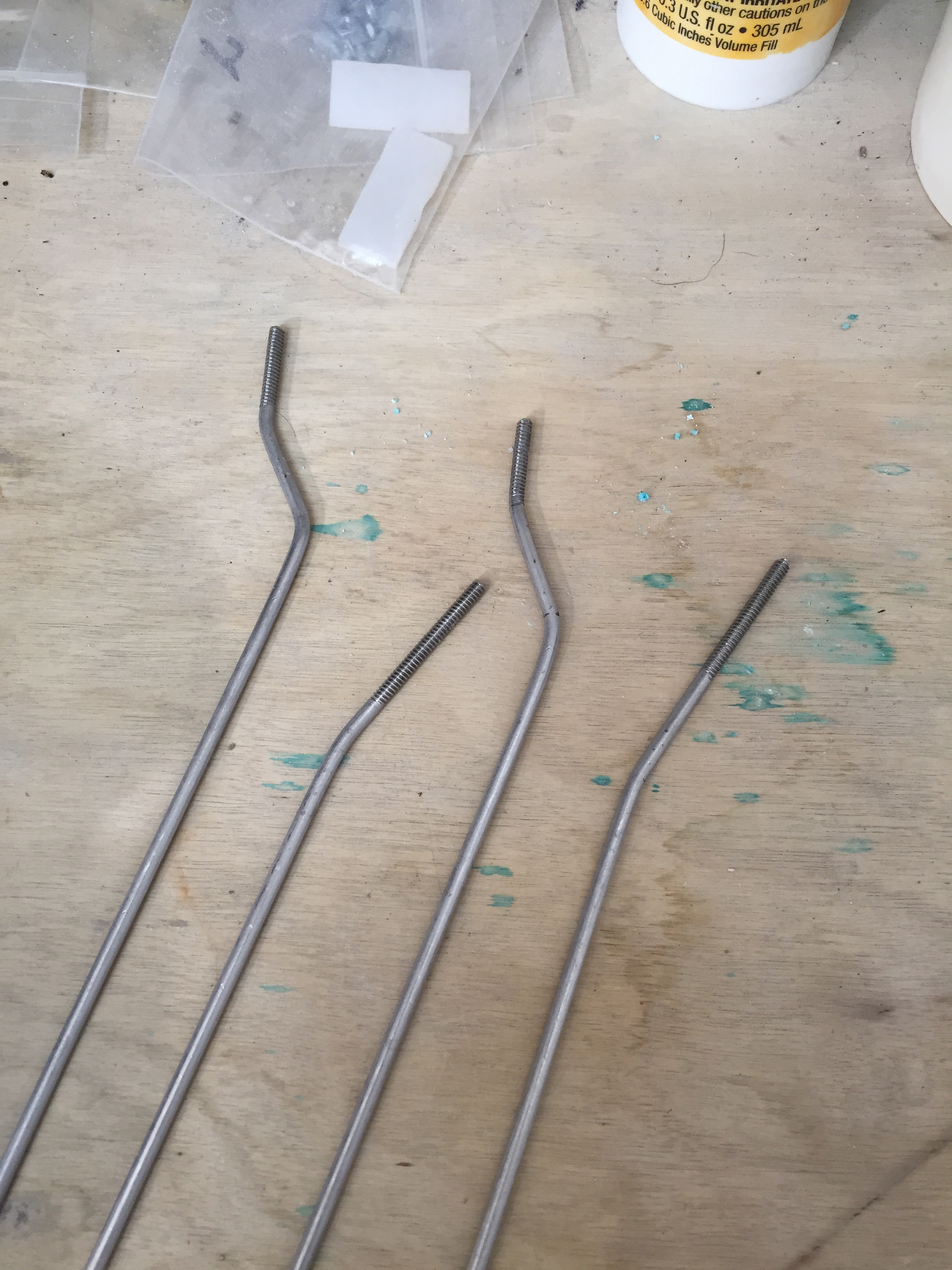
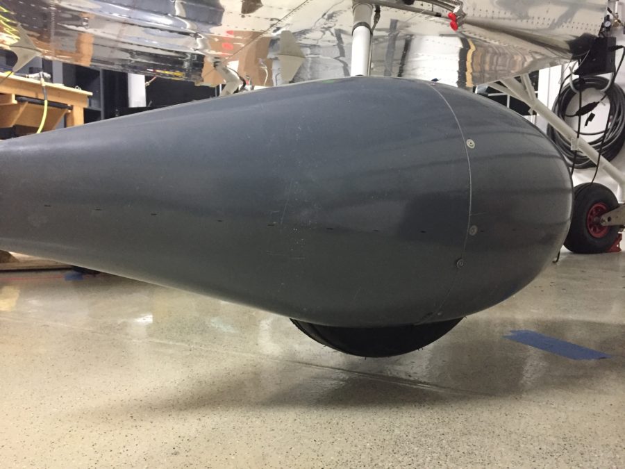
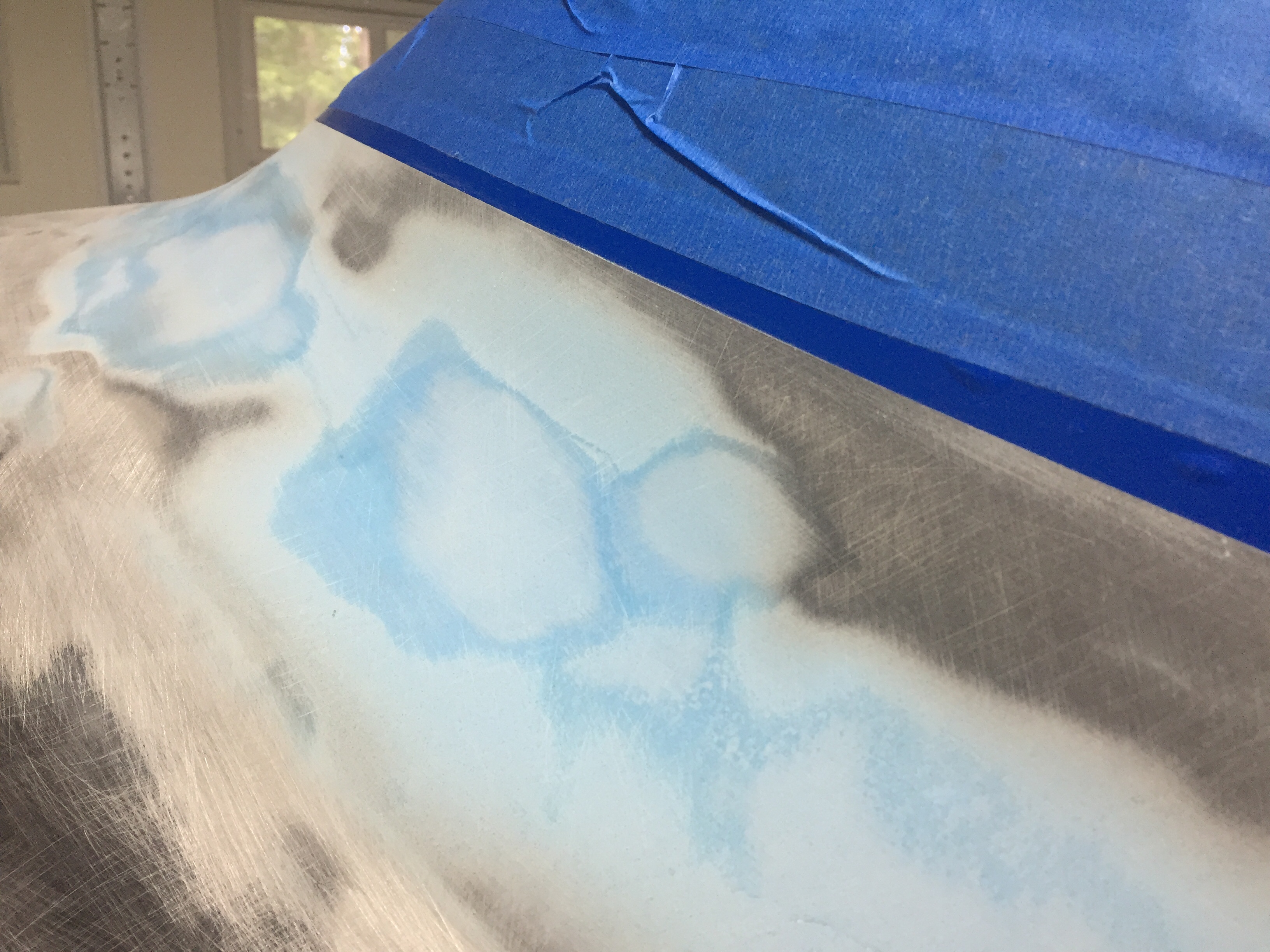
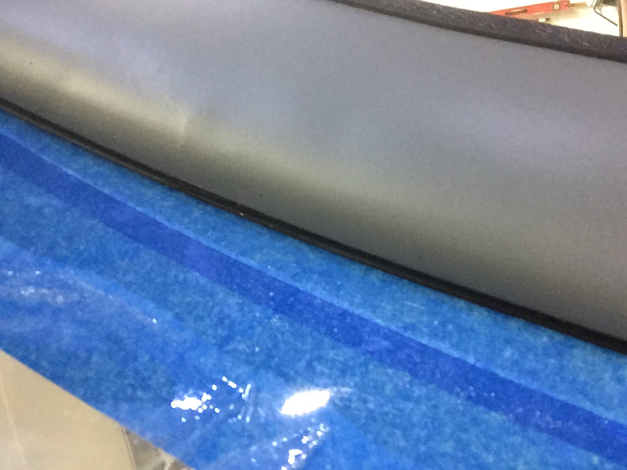
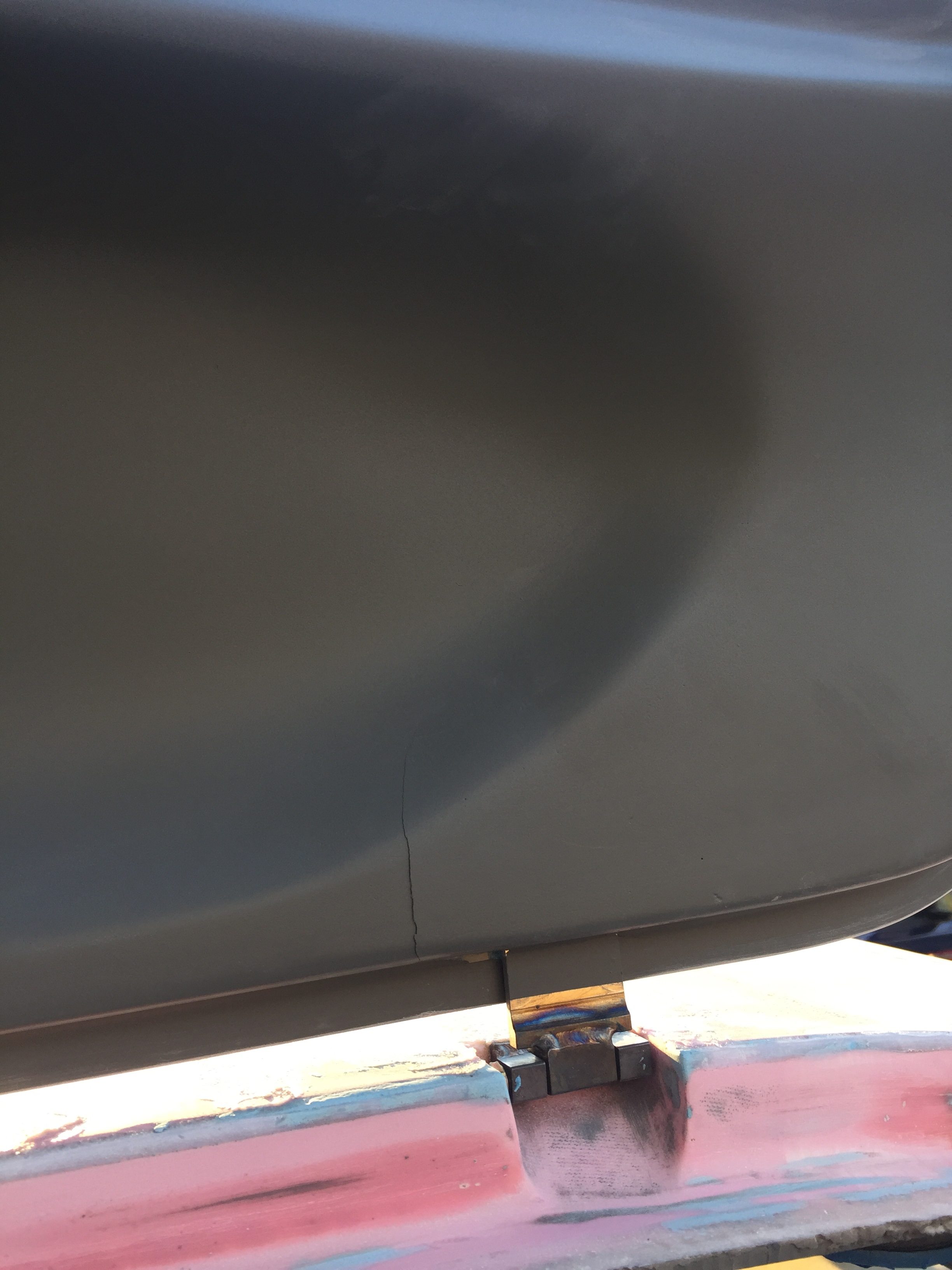
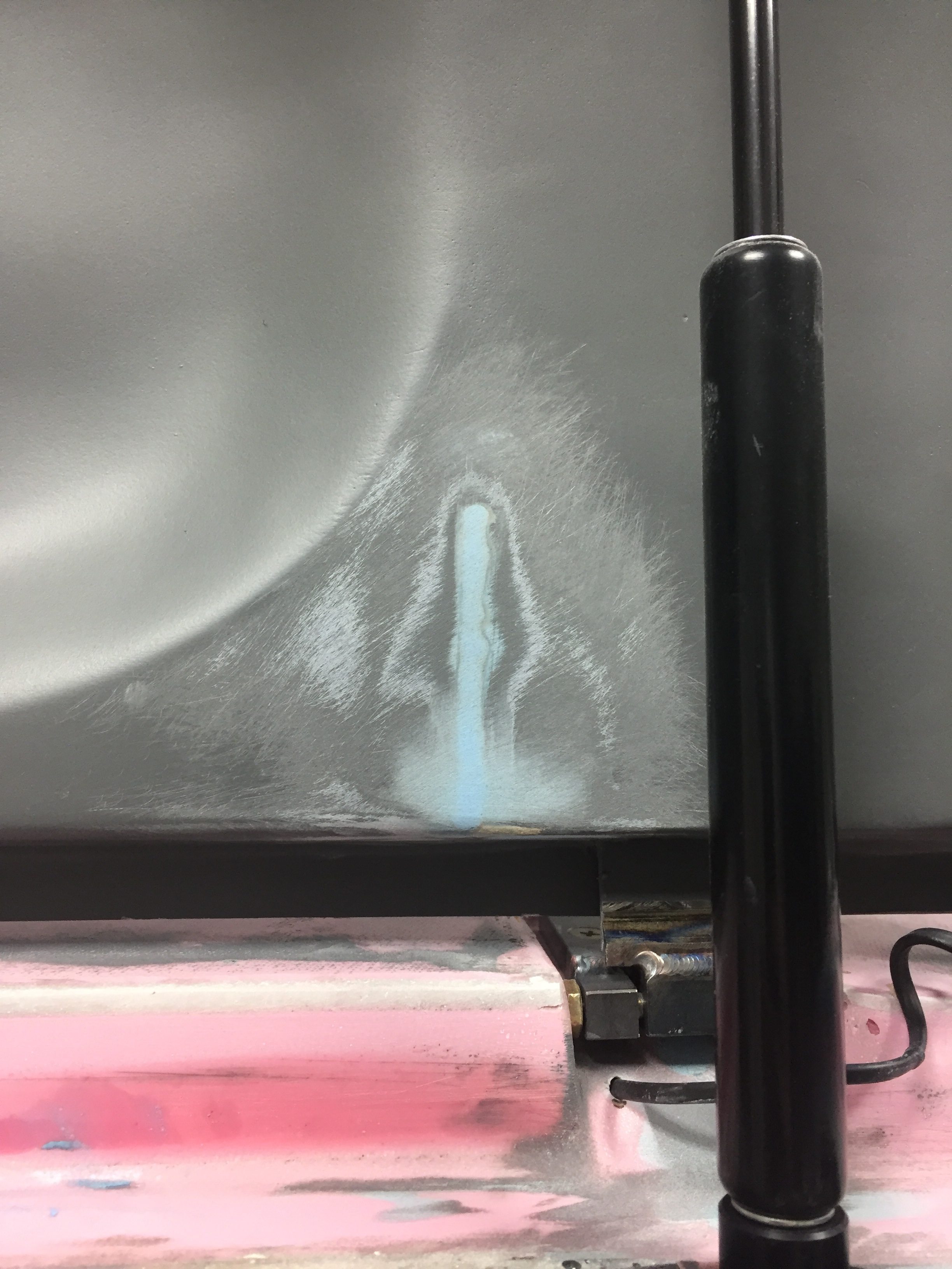
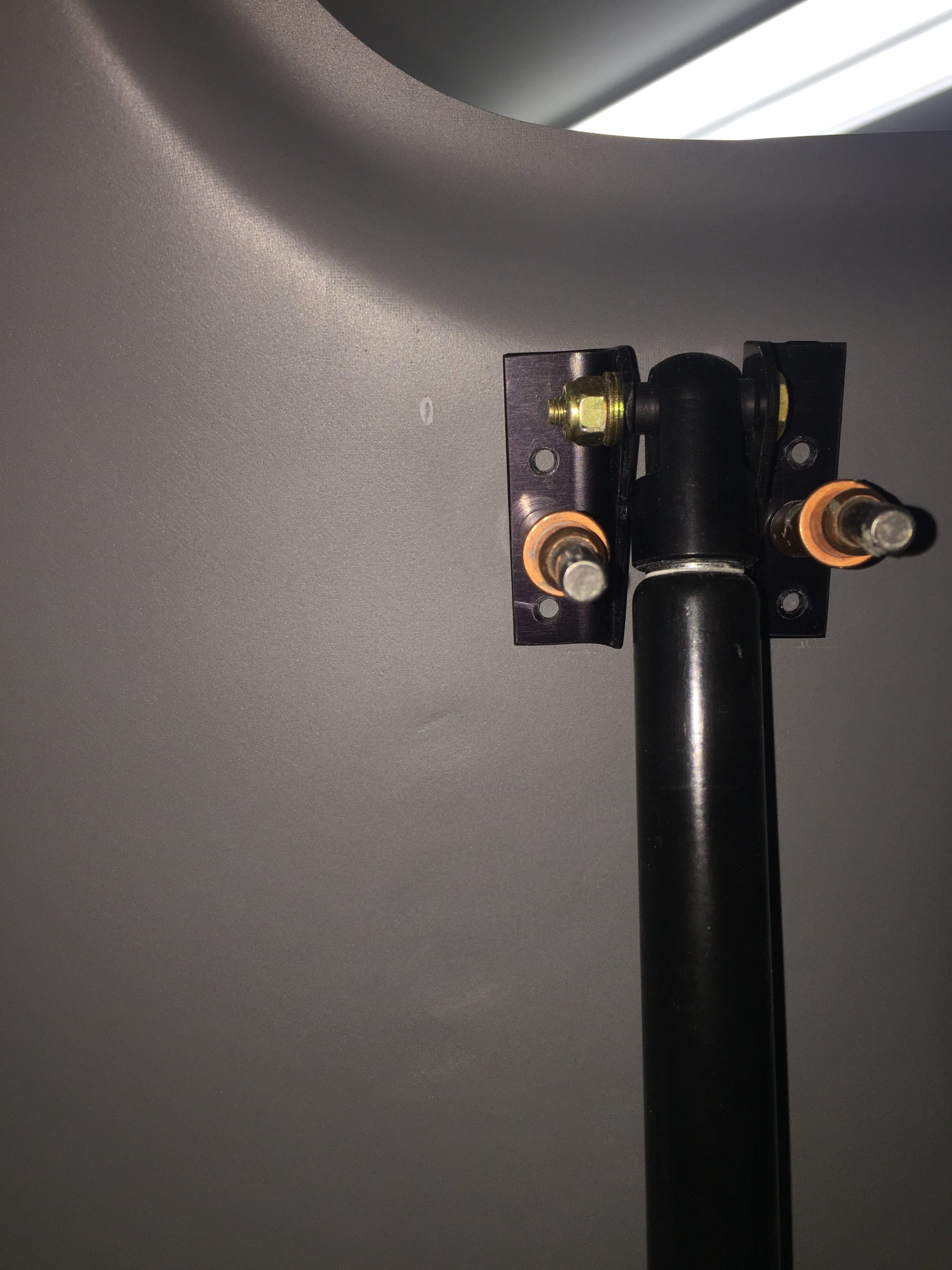
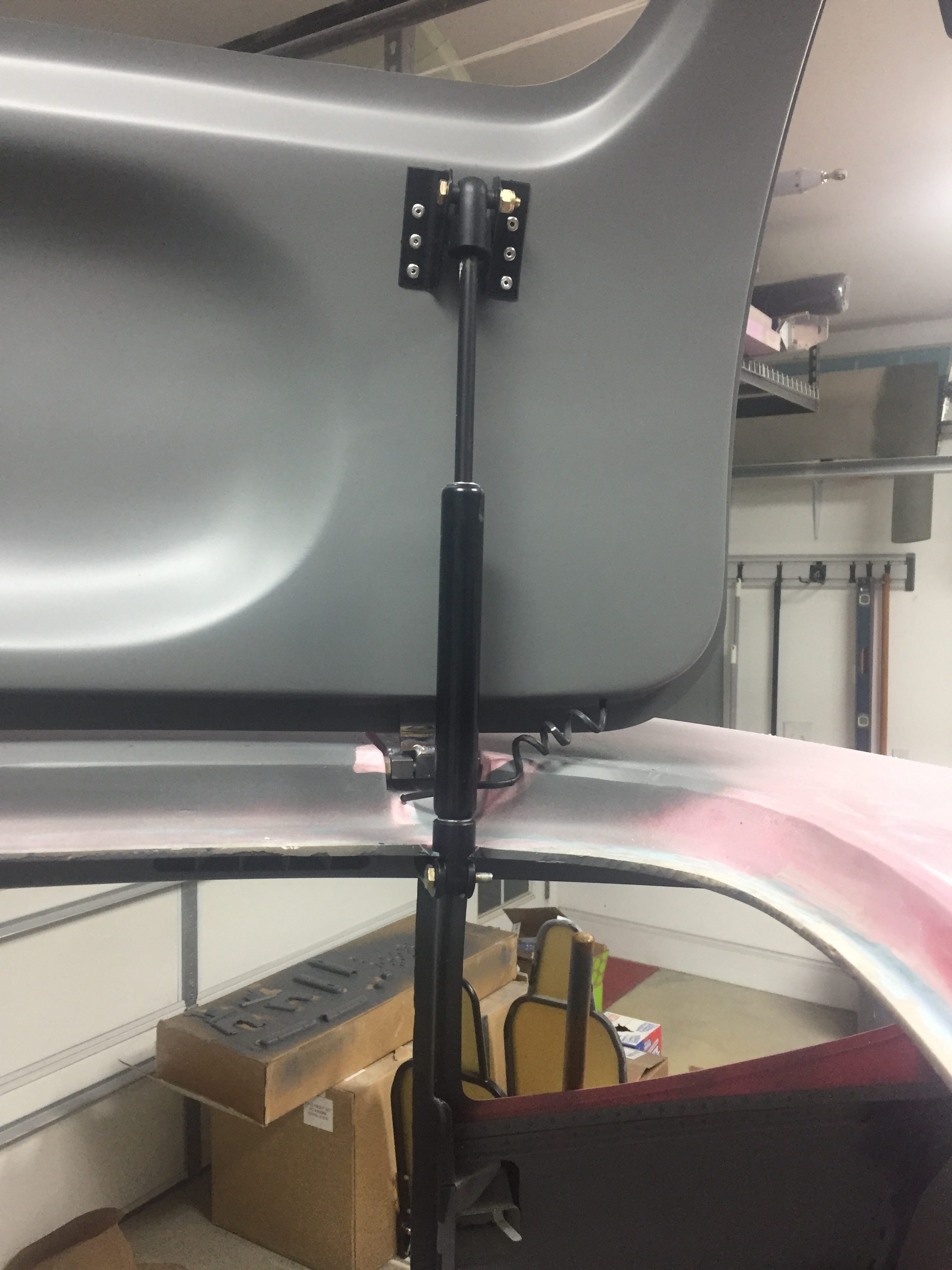
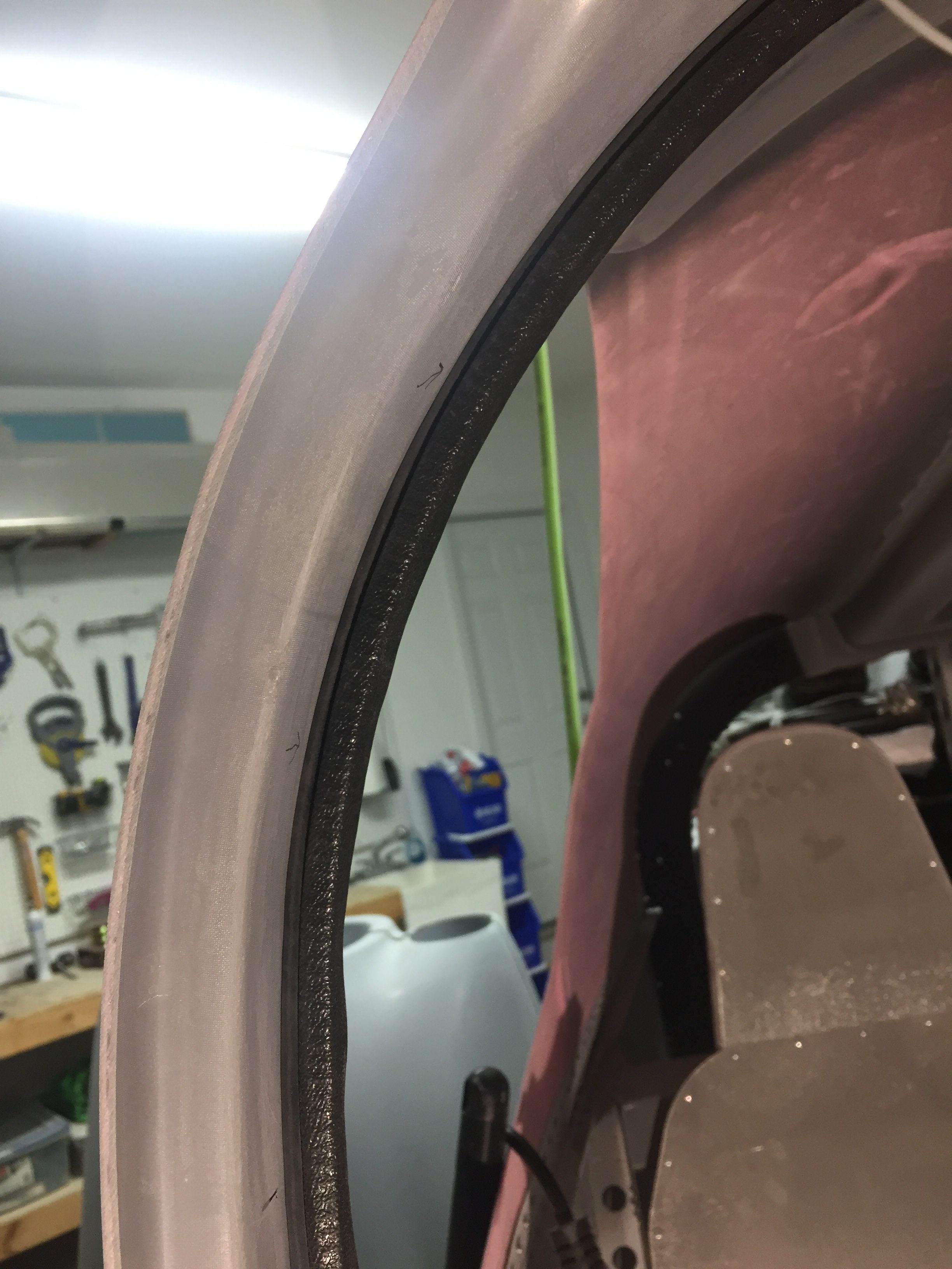
The end result is not too shabby, even if it’s not beautiful.  I hope it’s functional.  I finished cleaning the foam and set about reinforcing all of the joints with glass tape left over from tip fairings.  Once cured, I did a final fit and trim to provide about 3/8″ clearance from the cowl openings and evened them up with the induction ducts below.  This clearance allows the engine to vibrate and twist a bit within the cowl without cracking the ducts, as you don’t want the two rigidly attached to each other.  I really debated on how to close that gap, thinking about creating flexible ducts from the start or taking what I have at this point and using a rubber strip to seal it.  In the end, I copied an idea from the DA-40 I fly and ordered some bulb seal from McMaster Carr.  I’m hoping this will keep the air from leaking around the duct but allow the engine to move within the cowling.  Again, some testing during first few flights will tell.

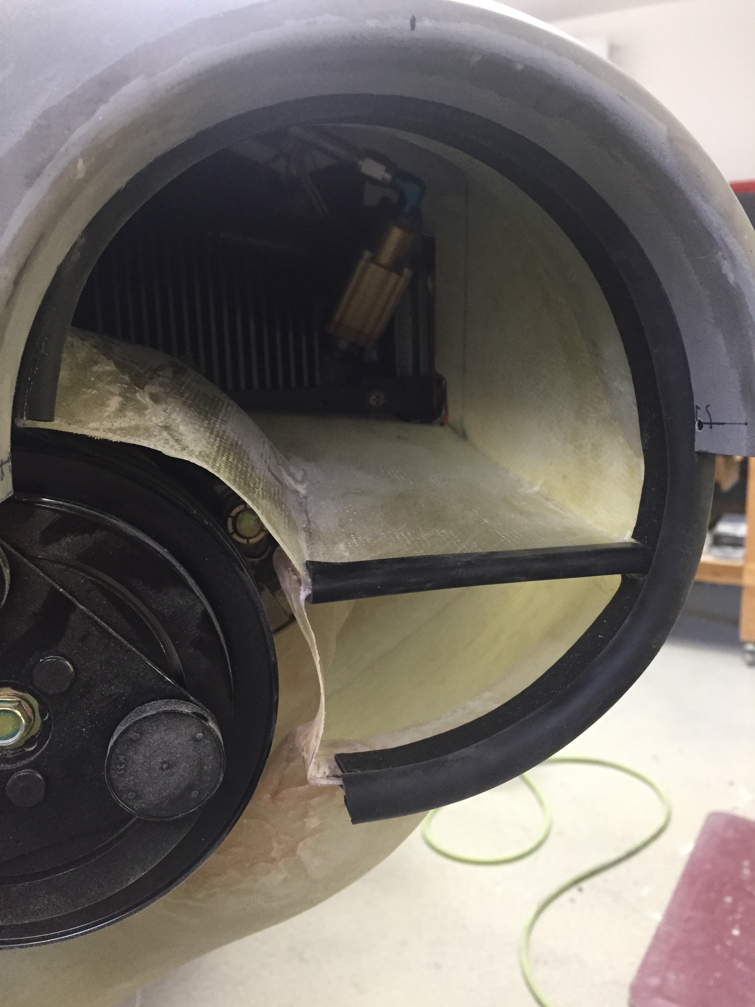
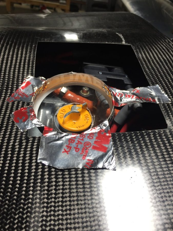
I may go back and cosmetically clean these ducts up before paint just to make them look good, but for now, I shot a coat of black paint on them to mask imperfections.  I still need to fabricate up a small ramp that will cover the exposed face of the compressor and help direct smooth air into the ducts.  If I find high temps on 1 3 5 clyinders during flight tests, I’ll copy Gaylon and pull the left induction intake to open that entire side to cooling.  I’ll be honest, this has really weighed on my mind how to create these ducts.  I’m sure there’s a better or fancier way of doing them, but for me, this is a good start.  If they work that’s great and if not, I at least have a good starting point.  These were the last items needed before cleaning the engine off and sealing the baffles using 3M firestop.

Put some pants on

The last big delivery of the project arrived containing our engine in a pickled state from Aero Sport Power.  A huge thanks to the guys on base who have helped me get the deliveries and saved so much headache by avoiding home deliveries!  I loaded it on the trailer with a forklift and then got it off at home by disassembling the crate and using my engine hoist to lift it.  It worked out quite nicely and I used a few cinder blocks to rest the pallet on so I could put the hoist away.

The engine was preserved (pickled) by Aero Sport since it will be a few months before first flight.  This prevents rust and corrosion from setting in and keeps everything coated with a special rust inhibiting oil until I’m ready to fire it up.  I couldn’t help but bolt the prop governor on and start working on the aircon compressor install, as I’ve been concerned with that for some time.  We’re off to a lack luster start.  The studs for the prop governor were about 1/2″ short and had to be replaced.  My steep learning curve with threaded studs in a Lycoming equaled a four day project to remove them, but thanks to Amazon aircraft tool supply, a little heat, and a smack with a hammer (great tip Darren at Aero Sport, thanks) the studs finally backed right out.  I replaced them with longer studs which are ludicrously expensive for what they are and a week after I started, torqued the nuts on the prop governor.

The aircon compressor was another swing and miss, not surprisingly I must admit.  I knew I had an original design bracket from Flightline and wasn’t sure if everything was going to work out.  My setup moves the alternator to the port side and puts the compressor on the starboard side.  Well, the brackets don’t allow the current compressor model to line up with the flywheel grooves.  The alternator also didn’t fit at all since the Plane Power alternators have a slightly smaller case than the antient models this was designed around.  Basically, nothing worked.

Of course, I had already taken everything apart and mixed hardware which was a huge mistake.  It took me an hour to sort things out and figure out where crap went back on the engine to be in original configuration.  Another call to John and Robert Skinner to brainstorm, I decided to push the easy button and buy the newest compressor and mount from Flightline.  That cost a lot, but I just don’t have the time, resources, or skills to engineer a new bracket and have it manufactured one off.  I know his newest setup works, so I sucked it up and paid the bill.

Meanwhile, the last project to do before hanging the engine is putting some pants over the beautiful red Beringer wheels.  The wheel pants and gear leg fairings add considerable efficiency to the airframe so it’s important to get these right and rigged properly.  I’ve dreaded them and was right in doing so.  For some reason, these were just a royal pain in the ass for me.  I started by building a jig to hold the main paints.  I used a laser to get all of the level and plumb lines which sucked.  Then I cleaned the two havles up enough to joing them together which also sucked.  What really sucked was trying to get the alignment perfect and the holes drilled in the right spots.

It sucked getting up and down off the floor about 50 times an hour too.  How was aligning the pants in the jig with the airframe?  It sucked.  I dropped a centerline for the fuse and then measured from that to set the alignment.  What sucks, is the new pants from Vans are grey fiberglass gel coat so you can’t see through them.  Which is why the directions suck because they assume you can just shine a light through the pants marking the proper holes to drill.  I finally sucked it up and used a combination of careful measurements and the laser to pinpoint the locations to drill into the pants and mounting brackets.

It also sucks trying to mark the wheel area to be cut out because you essentially have to mold yourself into the concrete floor to look underneath the pant that is three inches off the ground.  I’m using SkyBolts on the wheel pants, which suck to install, but will make maintenance and access so much easier in the long run.  I had to drill out the mounting holes slowly to ensure alignment stayed true, but they came out nicely in the end.  It also sucked that I forgot my wheel pant axle stand off was an aftermarket purchase to replace the stock Vans part which – you guessed it, sucked.  The stand off was way too long (by design) but I was afraid to trim it.  Eventually, like Tess’s wheels, I put my big boy pants on and cut the damn things off to length, never looking back.

But wait, that was the easy part!  The second sucky task was to do the gear leg fairings that cover the legs and brake lines.  Hide your house cats, because you have to use about 25 yards of string through all of this.  Wrapping string around the gear leg fairings and steps, you use that to align them with the prevailing wind in flight.  I can’t even begin to describe how I did it, but it worked.  Measuring, plumb bobs, levels, digital inclimometers, string, lasers, string, and lots of painters tape and string plus some more string all sucked into one giant suck.

In the end, it was worth the work to have properly aligned and nice looking pants.  I’m often complimented on my pants, and now my airplane will be as well.  I repeated much of the process for the nose gear using the workbench and engine hoist to level the fuselage off the ground as in flight condition..  I trimmed my nose gear leg fairing a bit too much, so may add a bit more material back before paint, but it’s fine for now.  I also attached the RV Bits intersection fairings and chose to split them with the pants as others have done instead of per plans.  This does not suck and makes for a much cleaner look in my opinion.  I epoxied them in place and will finish the filler and sanding work later after initial flights to save build time now.

Phew, even writing that sucked.  Enough of that, let’s hang an engine!

Smooth details

One of the last big fiberglass tasks is to layup the windshield fairing to the upper forward skin.  It’s a involved process with 10 layers of varying width glass strips followed up by a few coats of filler and epoxy to get it all nice and smooth.  I used cardboard to make a 7″ radius template and cut all of the fiberglass in preperation to layup the fairing.  I took other’s advice and died the epoxy black that will help create a nice finish from the inside with the Sika primer painted on the plexi.  This avoids unsightly views of the fiberglass from inside the cabin.  No pictures of the process as I had epoxy and fibers all over me, but it was a long afternoon with a lot of mixing.  I found that it was difficult to keep the layers precicely on top of each other and wound up with a few lumps and bumps along the way.  All were under the template radius, however, so could be fixed with filler.

The layup turned out pretty well and the next step is to apply filler.  I ordered a 2 mil vinyl plumping tape from Amazon Officially Approved Totally Legit Aircraft Supply Company and applied that over the electrical tape that marked the edge of the fairing.  This is probably the hardest aspect, as getting a nice smooth and even line is a bit challenging.  In the end, I did a lot of measuring and then eyeballing to get it good enough.  It probably isn’t perfect, but it looked good to my discerning eye.

My first coat of filler was the West epoxy mixed with micro to give some good ridgity over the layups.  I died it black just be be sure a good coverage again and made it good enough under the template.  After a quick sanding once dry, I used SuperFil to complete the curve which is much easier to apply and sand.  All in all, it took about five applications to get everything just the way I wanted it.  I used my favorite soft curved sanding block to sand and just judged by feel any high or low spots.  I’m happy with the turn out and I’m sure Jonathan will touch it up when he takes the plane for paint next year.

On the inside, I have one little streak of white from the tape which is a bit aggrivating, but nothing I can do about it now.  It may be covered by the side panel and glareshield, so not too worried about it, but it just annoys me.  The rest of the windscreen interior turned out absolutely perfect.  Again, the Sportsman method of taping and using Sika was a huge aspect of getting a clean finish.  It’s really cool to sit in the cabin now and look out through the windscreen!  It’s also nice having the cabing almost entirely closed in to keep it clean.

I am getting the last bits of interior from Aerosport and putting them in place as I go.  The panel inserts came with the seats and turned out great.  They are easy to install and really add a bit of class and color to the interior.  The baggage bulkhead looks great as well with the EXPERIMENTAL embroidered on the leather.  I’ll be putting a mesh grille in the cutout for the aircon return vent.

I finally got started on the wheel pants as well now the gear is on and it’s exciting pulling more parts down from storage.  I really want these pants to be finished well and have a nice fit, so I’m taking my time prepping the seams and mounting points.  I’m going to use SkyBoltz instead of traditional nutplates to allow quick removal and installation of the pants.  I don’t plan on having access doors for the valve stems because I just don’t want to do the fabrication neccessary.  This way it forces me to have a good look at the tire and brake while checking pressures monthly.  FYI the SkyBoltz are far cheaper direct than from ACS.

One issue I had to pause on and get some help was the wheel pant spacer that bolts onto the wheel nut for the main gear.  On initial fit, it’s proving to be way too long and I was hesitant to cut it allowing the rear portion of the pant to fit.  Beringer says trim away, however, so I think it’ll actually save me a few steps later in the process since I’ll be able to trim at a precise angle to match the pant and avoid using flox to build up a flange on the inside of the pant.

Meanwhile, I fabricated the last of the stainless steel brake lines and installed them to the calipers.  I am now considering swapping the calipers from side to side which will put the bleeder nipple on the bottom.  I’ve always had the nipple on the top of the calipers, but using a pressure bottle to bleed the brakes from the calipers up will allow the air to be pushed up naturally instead of forcing it down and the nipples should be the lowest point in the system for this.  If the lines can still be used, I’ll swap them.

Next up is some exciting stuff as we jet off for vacation and engine build school in Kamloops, BC.  Stay tuned for details!

Nope, doors still aren’t done

Have I mentioned doors suck?  Next airplane I build will be open cockpit.  I pressed on with fixing the outside gap and leveling the doors with the cabin top.  As I did with the pilot side, I used the door itself on the copilot side to create a mold in wet epoxy and then trimmed to a rough shape while still setting up.  What a neat trick, thanks Kurt!  Sand, fill, repeat.  Woof, I’m tired of this and very happy I didn’t build a Velocity composite airplane!

Finally, I got to a point where the door gap was consistent and had a proper gap so time to move onto fairing the doors to the top.  A few spots on the frame were lower than the door which resulted in a uneven profile.  This is where the SuperFil is really nice, as it goes on smoothly, is lightweight but strong, and sands wonderfully.  The key is to be patient and not make it perfect with the applicator.  I’m bad at that and wind up causing more work for myself down the road.  Either way, its more sand, fill, repeat to get a good profile around the doors.  I found the pilot side to be a bit worse than the copilots on the aft edge, but better on the forward edge.  On the bottom of the doors where it meets the aluminum structure, I sanded the door face down to smooth the transition, as it didn’t need much.  I figured that would be better than trying to put a few layers of filler on the aluminum.  I’m quite pleased with the way that turned out and it was an easier job.  Meanwhile I continued to perfect the jams, filling and sanding little spots that I saw or felt.

With the process of using the doors as molds, combined with the earlier paint issue near the door strut, I needed to touch up some paint spots again.  I took advantage of the need to fix a crack that had already developed on the left side aft hinge cover.  This was from me twisting the door inadvertently while working on the pins.  I used a Dremel to dig down to the joint between the wood and glass and filled with 5 minute epoxy then filler.  Now, that would have been a quick fix except that I doubled my work load by closing the copilot door on the air hose causing the same issue on the aft pin on that door too!  But wait!  Call now, and I’ll screw it up even further for only shipping and handling!  I later went on to shove the fuselage back into the garage after a final (ha, no not final) cleaning with the doors open.  Guess what doesn’t fit in the garage with the doors open?  Yup, twisted the door really good (glad it didn’t rip it off the hinges) and cracked another one.  Seeing a trend?

So three fixes later, plus a little TLC on the door edges, and they are ready for paint again, this time hopefully for good.  The outside of the door jams are also finally done and satisfactory to my standards.  This took a ton of time overall and was just as much work as I thought they’d be.  I could do it better and faster next time, but I doubt there will be a next time for me!  I rounded over the hard edge which will help the final paint on both the doors and the cabin top.  I wound up with a 2-3 mm gap all around and it’s close enough to the naked eye that it looks really nice.  I spent some time reinstalling the pin guides and really have the handles and pins dialed in for smooth operation.  I tested the seal temporarily on both doors and you don’t even realize it’s there now, which is perfect.

I took the chance to put a tape of glass over the seam between the top and the aluminum followed by two coats of fill to smooth the transition.  This will make a nice finish under paint down the road and is completely cosmetic, not structural.

The only Aerosport product left in the storage rack were the headliner panels, so I got those down and knocked off all of the dust.  They are a very thin layup of fiberglass that the headliner material will adhere to and then velcroed to the cabin top.  I needed to get them trimmed and fitted before putting in the windows, so spent a few hours on each getting just the right shape and fit.  It’s not hard, but it was a bit tedious as there isn’t a good way to get a pattern since each area and side is a bit different.  Lots of fitting, removing, trimming, repeat.  In the end, they fit very well and I’m excited to have them finish out the interior of what will be a very nice and comfortable cabin, no doubt.

I ordered two different color headliner material (available a lot cheaper from online retailers than Aerosport) and found one that matches very closely to the grey of the interior.  I’ll cover the panels down the road when I am between major projects.  The carpet from Aerosport came in and looks great in the bonus room upstairs.  This leaves a bit of paint left to complete the inside work.

The cart before the horse

Finishing the interior now consists of painting the remaining surfaces not covered by the Aerosport panels and painting the panels themselves.  The doors, door frames, and a few other areas needed the Presido gray applied and I wanted to get that complete so I could turn full focus onto the outside.  I took my time to prep the areas needing painting with paper and tape and then set to work ruining my index finger with four cans of spray paint.  I used the SEM sand free to wipe all the surfaces down after a good cleaning with a wet rag to get rid of dust.  I then primed a few spots that had the bare filler / metal exposed.  I then put three coats of color on it, letting it flash in between coats.  Finally it was two coats of clear on the doors and door sills.

I was excited to put the recently anodized hardware back on the doors to get the struts mounted for good.  The anodizing came out really nicely.  I had a few “trinkets and trash” done but the main parts were the seat belt brackets that I needed complete so the seats can be sent off for covering.  While installing the bolt holding the strut to the brackets, I managed to scrape off some of the newly applied paint.  I then proceeded to scream at the top of my lungs, collapse on the floor in a heap of fiberglass dust, and cried like a little school boy.

After that, I picked myself up and started asking questions.  SEM is advertised as a flexible dye, not a spray paint, for plastics, vinyl, and leather.  I know others had used it on their interior with good results so I was pretty confused.  I do have some spots on my carbon fiber overhead that have flaked off, but I attributed those to poor prep on my part, mainly not enough scuffing for it to properly adhere.  After a few dire nights thinking the entire interior may need to be stripped, I called their tech support and got reassured that the Color Coat is adequate for all substrates.  They did say it’s not going to be as durable as a two state professional coating, but it should be just fine and touch ups will be easy.  Sure enough, the areas I saw flaking was poor application on my part.  I tried pretty hard to scuff and scrape over an area I know I applied it correctly and the finish help up very well.

The need for a few touch ups is just as well, because I but the cart before the horse on painting and still needing to sand.  The external door gap was the next hurdle to tackle and I knew I really made a mess of it when fitting the doors originally.  While I used the cleco to cabin top method, I originally started with the plans directed 45 degree bevel before turning to square the door edges off so paint will stick better.  That left me with a large and unsightly gap between the cabin top and door edge seen from the outside.

Thinking smarter but not harder, I decided to put globs of filler on the top and then prep the doors to simply close and latch, creating a nice even gap all around.  I had seen others do this with layers of tape.  Now where they got that mystery tape, I don’t know.  I can’t find any tape thicker than about 20 mils and it’d take 200 feet and 10 layers to create a nice 2mm gap around the door edges.  So, I compromised and kept the globbing plan but simply wrapped the door with brown packing tape and shut it.  I then monitored the epoxy flox mix during curing to start working it as it hardened.  I just used razor blades to go back and cut by hand an even gap in the curing epoxy.  It was really easy and very clean.  The trick is to catch it at the right time.

I cleaned up the tape residue and a few areas of the flox and was really happy with the results.  It was a good base for poly fill to smooth everything out nicely.  It’s also a lot stronger than just the poly fill.  I rough sanded the epoxy to get an even more consistent gap and then put the first coat of poly fill on to dress it up.  Another sanding, this time with a lot of fine tuning pretty much finished it up.  A few spots have some pinholes or voids that will be filled in after an initial prime coat is applied to highlight any last defects.  It wasn’t nearly as much work as I thought it’d be and I’m happy with the outcome.  Now, on to the co-pilot’s door!

It’s not easy being pretty

I realized I forgot a post about installing the door seals after building up the door frame lip.  As always, it took more effort and involved more frustration than I had originally imagined.  To sum it up, my problem was not having a consistent gap between the door frame lip and the interior of the door.  I had some tight spots and some just right spots.  The issue are the tight spots that take a lot more force to squeeze the door seal bulb than you want to put on the door.  Basically, I had to start again with fitting once I got the seals.

My first idea to make the seal fit with less squish was to remove a lip on the u channel of the seal.  It’s designed to help hold the seal onto the door frame lip but it also added about 1/8″ of bulk.  While that did help, it wasn’t enough.  I tried different combinations of seals, but due to the uneven gaps, the smaller seal wouldn’t actually touch both surfaces in a few spots and adding filler would have required re-sanding and contouring the inside.  That wasn’t a viable option, so it was back out with the angle grinder and Scotchbrite pads to go to town on the door frame lip.

I was shocked at how much had to come off in some areas.  I determined this using a marker and template, acting as a scribe to measure the proper gap.  I used an area that had a nice amount of squish on the seal but not too much as a gauge for the entire door gap.  It worked well and after making a lot of dust all over the just cleaned interior, I was getting a nice fit on the door seals.  I know I’d have to add some filler on the door jams anyway to get them looking nice, I wasn’t too concerned about my grinding methods.  I mainly wanted a good fit, cosmetics will come later.

After a few evenings and a lot of opening and closing the doors, I had achieved a good consistent gap for the seal and was happy with the fit and function of the door seal.  I noticed that even after two nights of the door remaining closed, the seal was already getting broken in, making it easier to close the door.  Folks say these seals need to be replaced as they wear down, so it will be a maintenance item every other year or two,, I’m sure.  What I wasn’t happy with were the pins that held the doors shut.  The Plane Around latch was doing its job of pulling the door closed, but the back pin still needed to do some work to align to the block.  The pins I have are stainless with epoxied magnets in their tips and are shaped like bullets.  That sounds great if the doors are almost perfectly aligned, but they did a poor job of any movement into the aluminum blocks that I also had.  Even after a few weeks of working, the blocks were gouged and the bullets were wearing scars.

Luckily, a call to Sean at Plane Around solved my problem.  He had a set of angled stainless pins, much like the shape of the stock pins, that were hollow for a magnet to be dropped into.  These use setscrews to attach to the rods and can be positioned to most efficiently capture the blocks and align the pins.  He also has Delrin blocks that are machined to have a nice rounded funnel shape.  The stainless glides effortlessly on the Delrin making the closing and opening of the door handle a seamless effort compared to the rough metal on metal that I had.

It took some time to fit, because I had to cut the rods and machine the pins to orient them just right but the effort was worth it.  My doors now close perfectly with the seals and have a firm but easy motion in the handle.  I fine tuned the blocks’ alignment with shims which allows the pins to insert perpendicular to the block, reducing the friction along the way.  This has been a huge burden lifted, because while the doors were functional and airworthy, they weren’t easy or pretty.  Now they’ll be both.