Punching the punch list

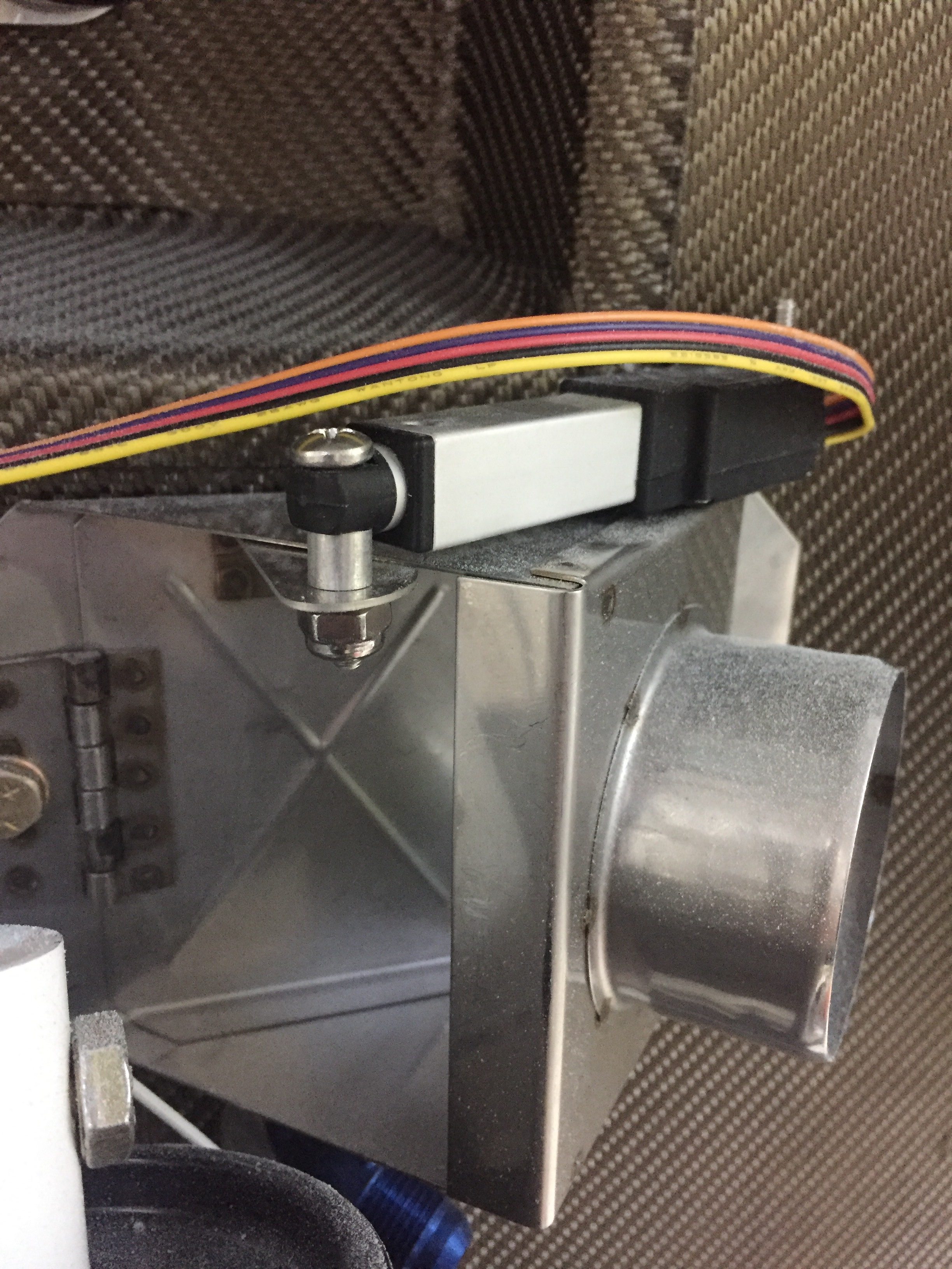
There are a lot of little jobs that go along with the big jobs on building a plane.  I’m trying to use my time efficiently while waiting on the engine to knock out a bunch of them.  The first was fixing the arms and servos on the heat ducts up front.  An order to ACS and a few minutes at the band saw and the servos for the heat and oil coolers were attached properly and pots adjusted for full travel.  I also spent an hour trouble shooting a bad pot for the rear heat duct, as I have a switch that allows either the front or rear rheostats to control the servo and the rear rheostat was inop.

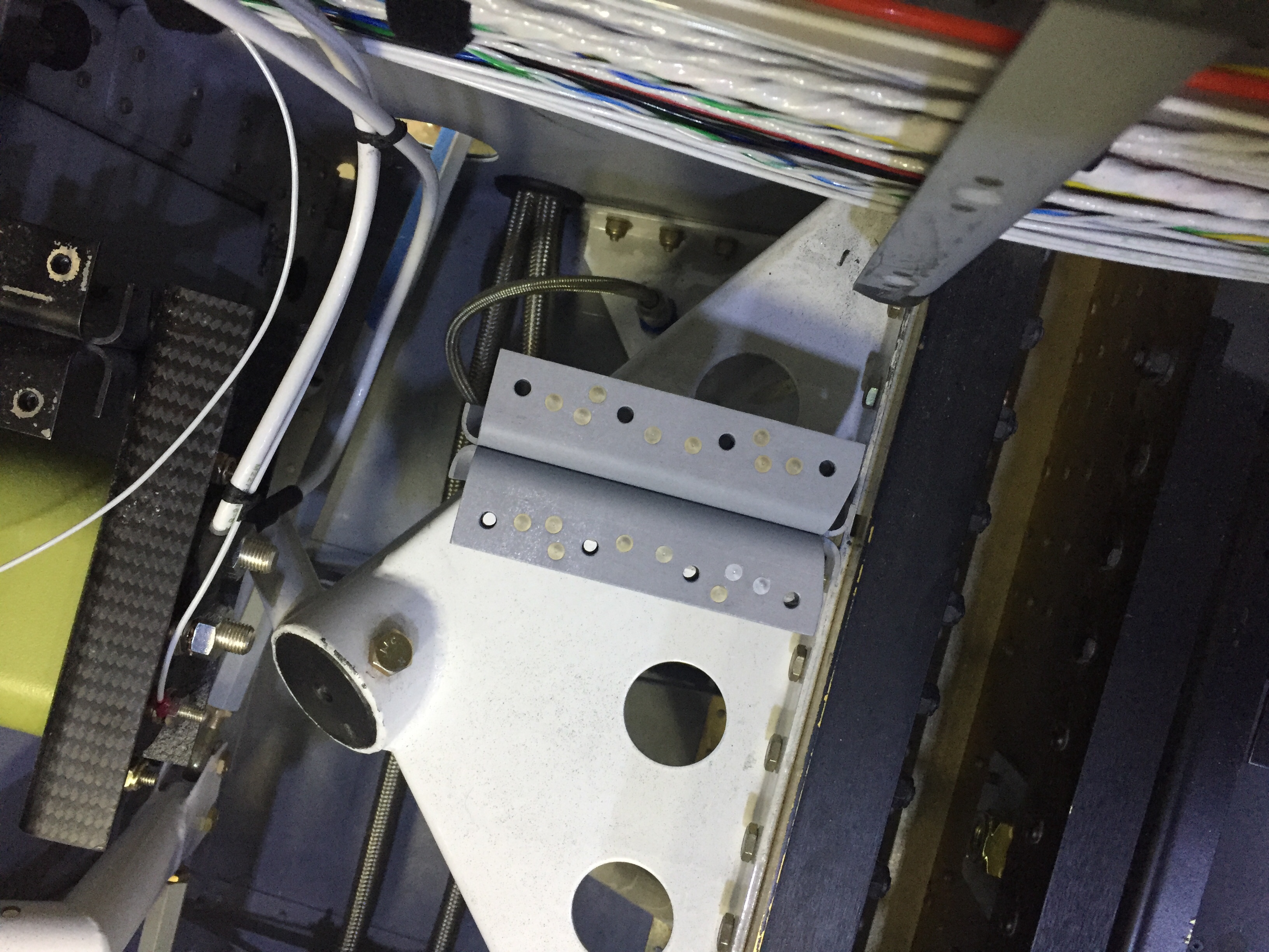
I cussed and bled in equal amounts installing the last of the seat rail brackets now the gears are on.  The nuts and bolts are not easy to access at this point, but you have to wait in order to install the gear bolt.  I also put in the last bolt and custom spacer for the GPU plug which helps reinforce the receptacle by attaching it to the seat pan.

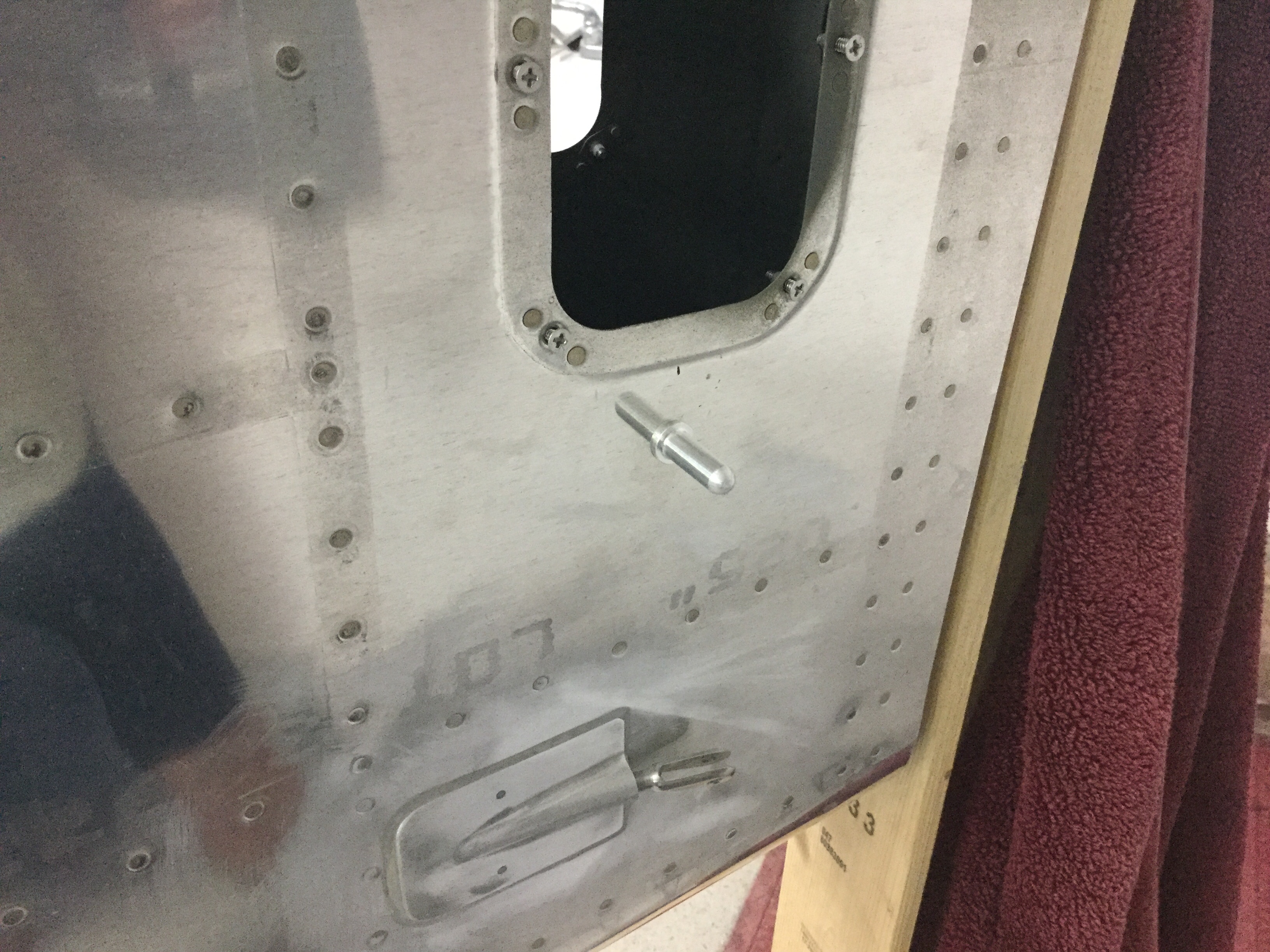
I ignorantly forgot to install the transponder antenna before buttoning up the tunnel, so I had to take the center console, tunnel cover, and lower instrument panel off to get down in there.  Of course I burried it near the core of the earth which made access tricky to say the least.  I was able to squeez my hands down there and got it all bolted on with the coax attached.  I knew I had left one fuel line untorqued but couldn’t remember which one so checked all fuel line fittings for proper torque.

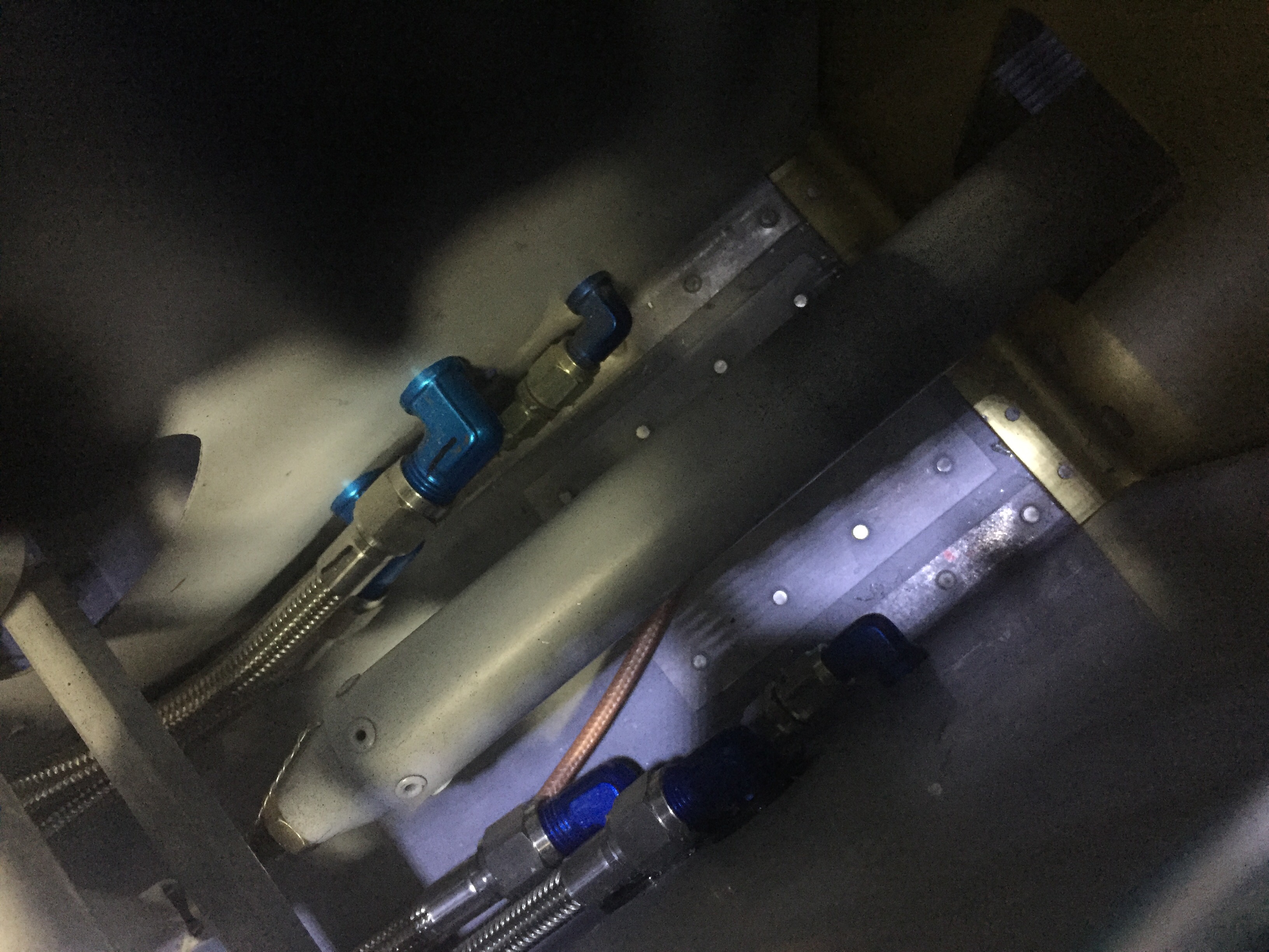
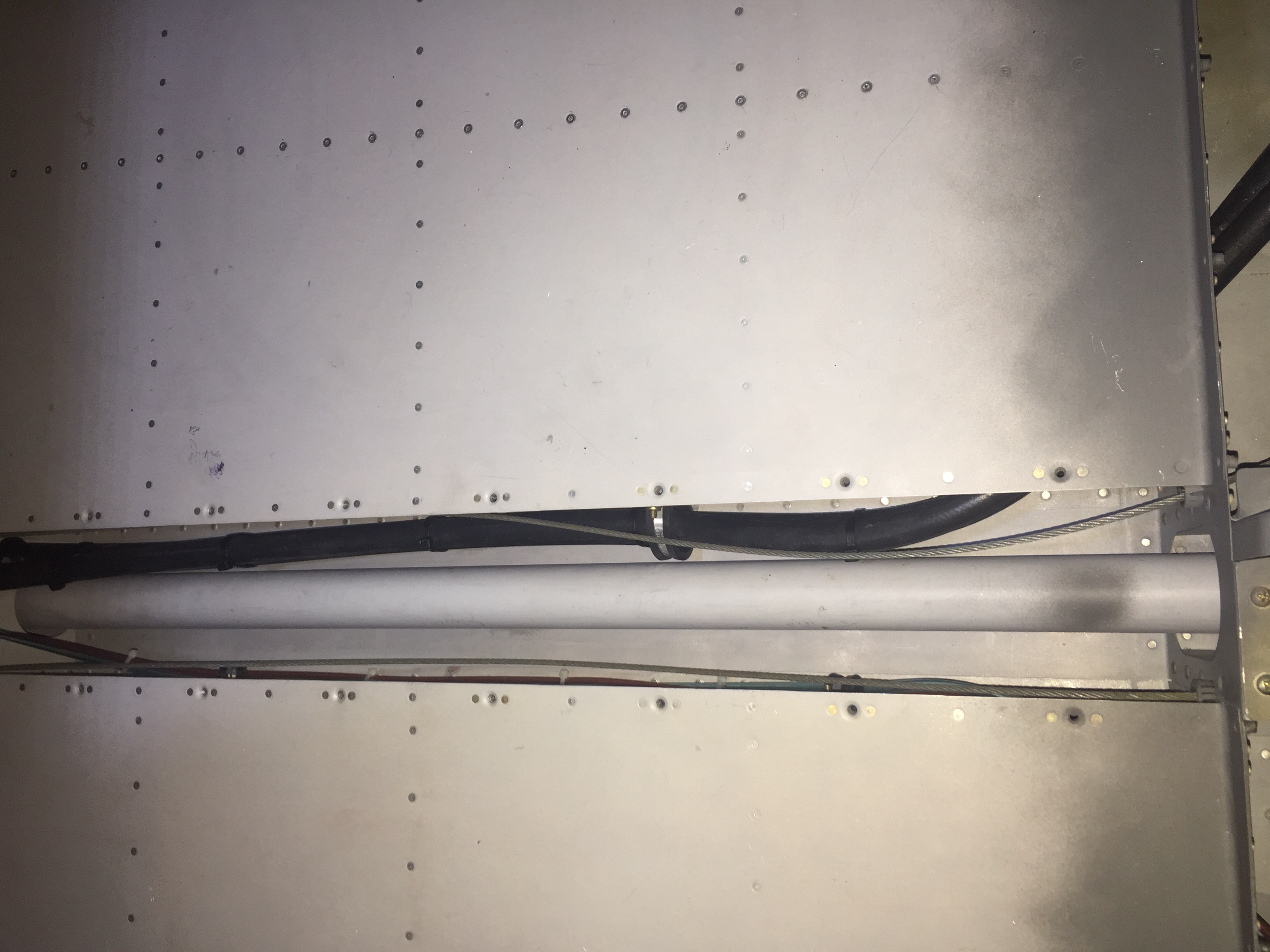
The last task in the rear tunnel is to secure the aircon lines which I did with some hose clamps and edge grommet material.  Again, not fun to get to the hardware but it was doable and will rarely if ever be removed.  The lines are now secure and fit nicely in the tunnel, I’m glad I didn’t run them down the side of the fuse.  I also secured the last little sections of the O2 lines in the tunnel.

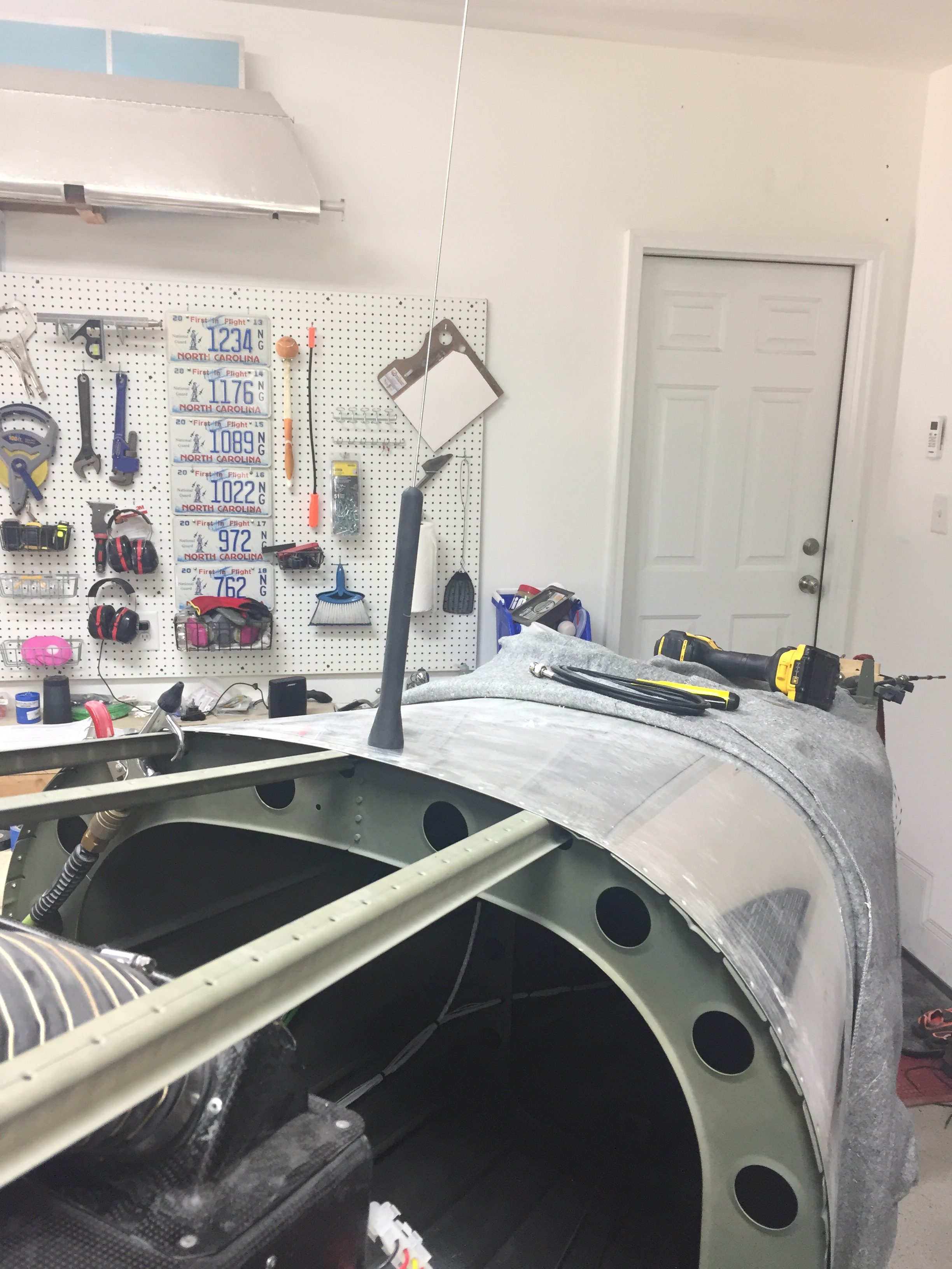
My ELT antenna placement has been a topic of disagreement on VAF, as I really wanted to avoid mounting it on top of the tail cone.  It’s big, ugly, and ugly.  Mainly, though, it’s ugly.  It’s also essential to my life and the lives of my passengers should the worst happen and we have an accident, so I guess it’s important to do it right.  I debated on doing some reception tests with it mounted internal to the tail cone, but honestly, I just got lazy and decided it really isn’t that ugly.  In the end, I chose to do it the right way and put it on the top of the tail cone.  The cable was secured along a bulkhead and the last of the wiring clean up for the O2 tank / ELT was completed.

I love spending time wiggling back into the tail coffin, I mean cone, so I made a fort with blankets and towels and dove in to attach the OAT sensors to the ADAHRS and finish securing tail cone wiring.  I put the OAT sensors below the access panels underneath the horizontal stab since I had all of my wing wiring complete and for shorter wire runs to the ADAHRS.  Since they have to be calibrated anyway, I’m not too concerned with exhaust from the engine affecting them too much.

The O2 tank was put back in for good and connected to all of the lines.  I also attached the pitch auto pilot servo to the bellcrank and will connect the yaw servo once the tail feathers and rudder cables are rigged at the hangar.  That is the last task in the tail cone and can be completed without having to crawl all the way back there.  It’s going to be motivation in life to keep from getting fat or have a small child that can slide back there for maintenance, it’s a very tight fit with all the extra stuff I put back there.

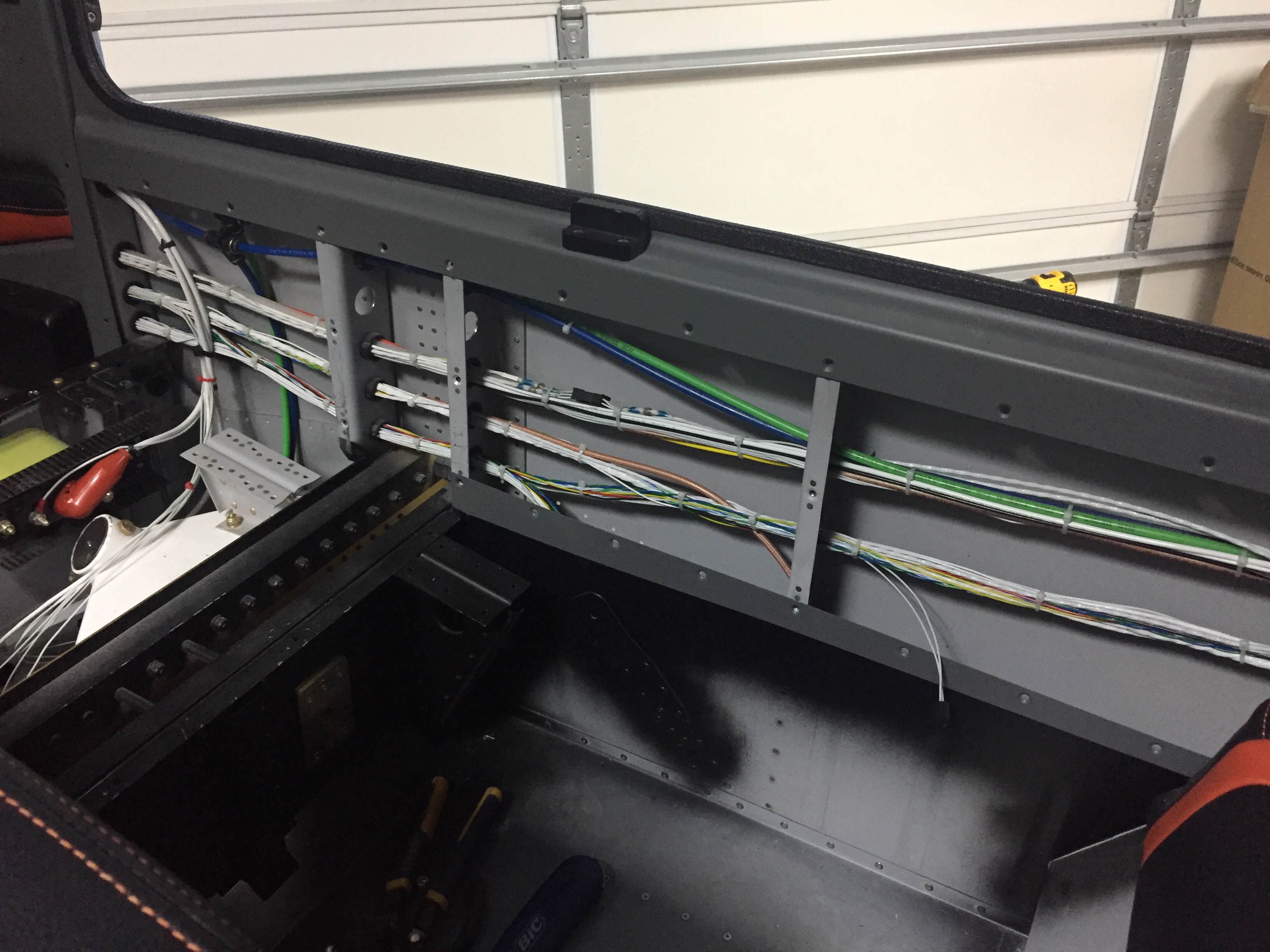
More zip tie work on the side walls as I cleaned up all of the wire bundles.  I was lazy and didn’t lace them.  If you don’t like that, you go build your own damn airplane!  Lots of zip ties.  Overall I’m happy with the wire runs, I was able to keep coax with mainly data / signal wires and have the high current ones seperated.  I have seen plenty of aircraft with everything bundled together without issues, so I think it’s more important to terminate and ground properly than anything.

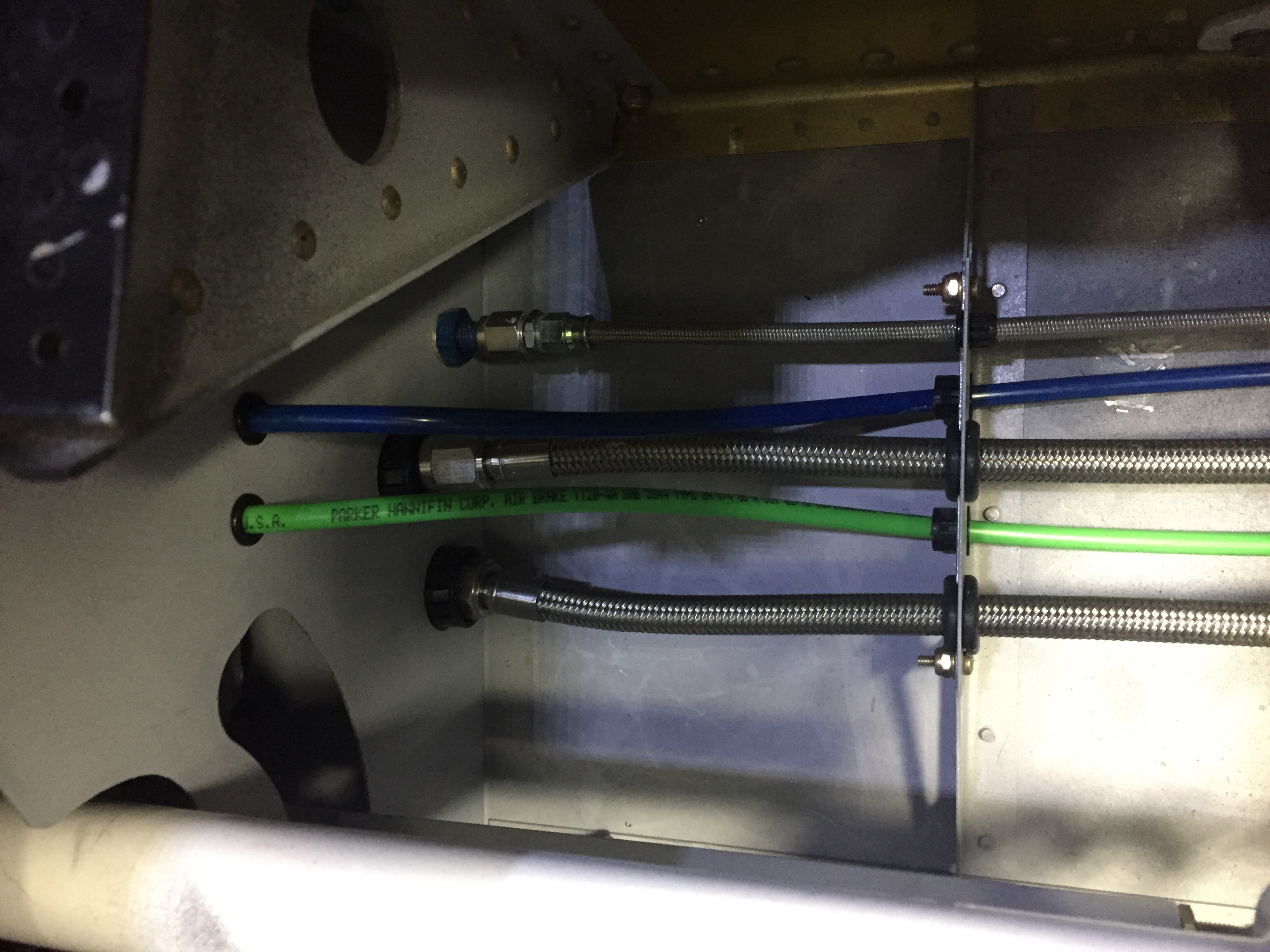
The pitot / AoA tubing needs to run across the fuselage from the left wing to the right sidewall, so I put two holes in the tunnel and used free holes from the fuel line anchors to run the blue and green tubing.  The wing is already plumbed, so these lines will connect with those from the wing with two connectors and be done.

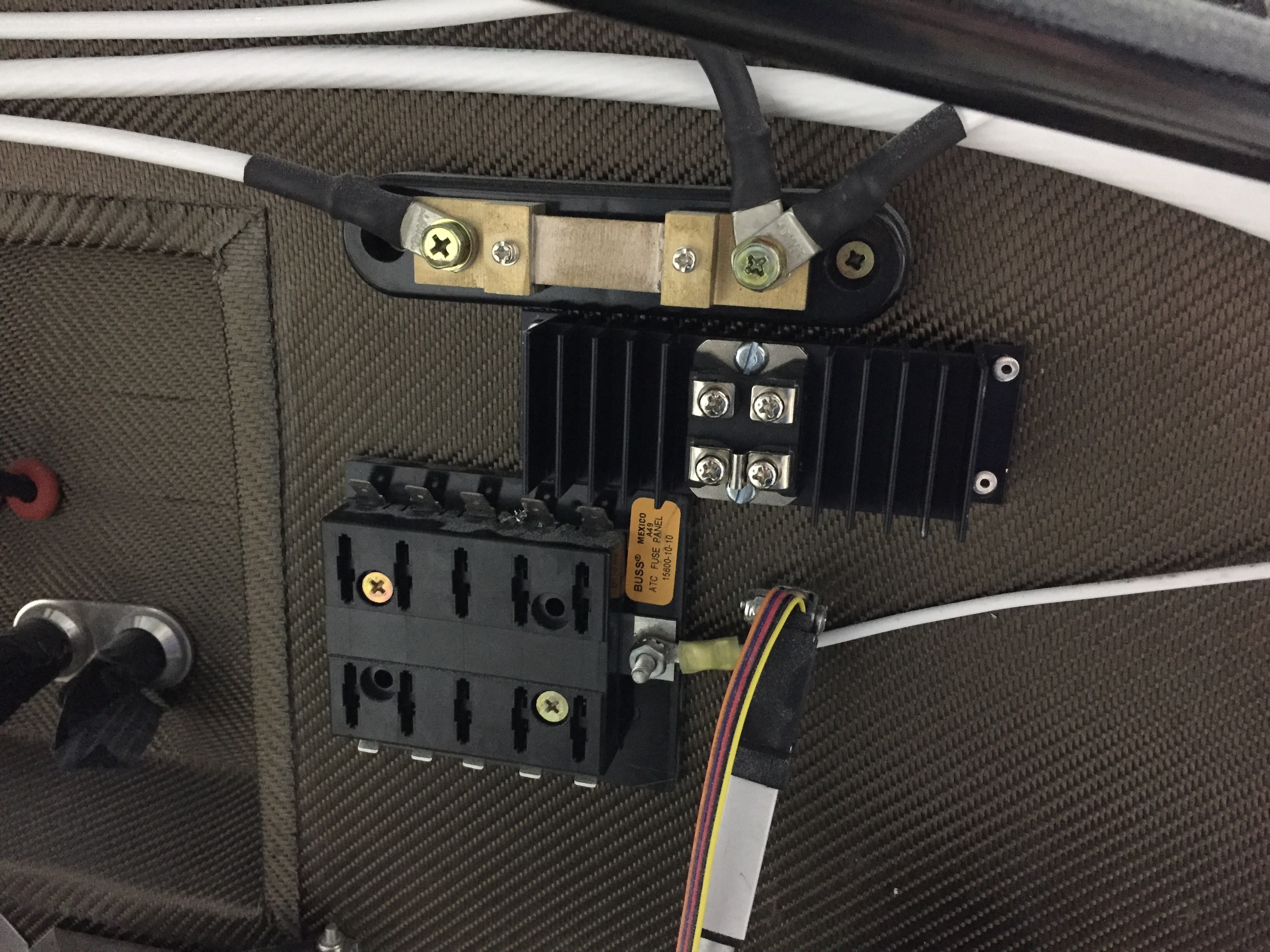
Finally, I put the 30 amp Schottky diode on the firewall between the shunt and engine fuse block.  I had this in my electrical design but just in the wrong location.  It provides redundant power input to the engine fuse block only, keeping it from backfeeding the rest of the electrical system.  The power comes in from the emergency engine power switch which comes from the battery to the fuse block.  Big picture, it is a redundancy for the single point of failure of the master contactor or short in the system.  A complete electrical failure or engine stopping SOP will be to turn off the master switch (leaving PFD, MFD, and G5 operating on independent back up batteries) and switch on the emergency engine power switch.  If the battery has any juice at all, it will go only to the engine fuse block.

Smooth details

One of the last big fiberglass tasks is to layup the windshield fairing to the upper forward skin.  It’s a involved process with 10 layers of varying width glass strips followed up by a few coats of filler and epoxy to get it all nice and smooth.  I used cardboard to make a 7″ radius template and cut all of the fiberglass in preperation to layup the fairing.  I took other’s advice and died the epoxy black that will help create a nice finish from the inside with the Sika primer painted on the plexi.  This avoids unsightly views of the fiberglass from inside the cabin.  No pictures of the process as I had epoxy and fibers all over me, but it was a long afternoon with a lot of mixing.  I found that it was difficult to keep the layers precicely on top of each other and wound up with a few lumps and bumps along the way.  All were under the template radius, however, so could be fixed with filler.

The layup turned out pretty well and the next step is to apply filler.  I ordered a 2 mil vinyl plumping tape from Amazon Officially Approved Totally Legit Aircraft Supply Company and applied that over the electrical tape that marked the edge of the fairing.  This is probably the hardest aspect, as getting a nice smooth and even line is a bit challenging.  In the end, I did a lot of measuring and then eyeballing to get it good enough.  It probably isn’t perfect, but it looked good to my discerning eye.

My first coat of filler was the West epoxy mixed with micro to give some good ridgity over the layups.  I died it black just be be sure a good coverage again and made it good enough under the template.  After a quick sanding once dry, I used SuperFil to complete the curve which is much easier to apply and sand.  All in all, it took about five applications to get everything just the way I wanted it.  I used my favorite soft curved sanding block to sand and just judged by feel any high or low spots.  I’m happy with the turn out and I’m sure Jonathan will touch it up when he takes the plane for paint next year.

On the inside, I have one little streak of white from the tape which is a bit aggrivating, but nothing I can do about it now.  It may be covered by the side panel and glareshield, so not too worried about it, but it just annoys me.  The rest of the windscreen interior turned out absolutely perfect.  Again, the Sportsman method of taping and using Sika was a huge aspect of getting a clean finish.  It’s really cool to sit in the cabin now and look out through the windscreen!  It’s also nice having the cabing almost entirely closed in to keep it clean.

I am getting the last bits of interior from Aerosport and putting them in place as I go.  The panel inserts came with the seats and turned out great.  They are easy to install and really add a bit of class and color to the interior.  The baggage bulkhead looks great as well with the EXPERIMENTAL embroidered on the leather.  I’ll be putting a mesh grille in the cutout for the aircon return vent.

I finally got started on the wheel pants as well now the gear is on and it’s exciting pulling more parts down from storage.  I really want these pants to be finished well and have a nice fit, so I’m taking my time prepping the seams and mounting points.  I’m going to use SkyBoltz instead of traditional nutplates to allow quick removal and installation of the pants.  I don’t plan on having access doors for the valve stems because I just don’t want to do the fabrication neccessary.  This way it forces me to have a good look at the tire and brake while checking pressures monthly.  FYI the SkyBoltz are far cheaper direct than from ACS.

One issue I had to pause on and get some help was the wheel pant spacer that bolts onto the wheel nut for the main gear.  On initial fit, it’s proving to be way too long and I was hesitant to cut it allowing the rear portion of the pant to fit.  Beringer says trim away, however, so I think it’ll actually save me a few steps later in the process since I’ll be able to trim at a precise angle to match the pant and avoid using flox to build up a flange on the inside of the pant.

Meanwhile, I fabricated the last of the stainless steel brake lines and installed them to the calipers.  I am now considering swapping the calipers from side to side which will put the bleeder nipple on the bottom.  I’ve always had the nipple on the top of the calipers, but using a pressure bottle to bleed the brakes from the calipers up will allow the air to be pushed up naturally instead of forcing it down and the nipples should be the lowest point in the system for this.  If the lines can still be used, I’ll swap them.

Next up is some exciting stuff as we jet off for vacation and engine build school in Kamloops, BC.  Stay tuned for details!

She’s got legs!

I continue to empty my parts inventory which is nice to give the space back to what it should be such as guest bedroom and bonus room upstairs.  A big chunk of floor space has been taken up by the windscreen.  Now, the story is I received my order from Cee Baileys many months ago but the box was damaged and the thoughtful FedEx driver decided to take the bundled plexi out of the damaged box and simply lay on the diamond plate steel floor before continuing the route.  Needless to say, my brand new windscreen was no longer brand new.  It’s not to say that it’s ruined, it just didn’t meet my standards.  I was lucky to only have a few tiny nicks that won’t even show up on a camera picture, but are visible if you look hard enough.  A claim and call back to Cee Baileys had a replacement in a better box on the way to me.  I plan to sell the original one at a good discount and it may work for someone building on a budget or as a repair, who knows.  Either way, my fuselage was ready for a windscreen.

I prepped it just as I did on the windows and since I had already rough trimmed it, I was able to get the final fitment completed in just one evening.  I’ll be using a mix of methods to install it, following the plans on the lower edge and using the Sikaflex method around the cabin top.  I again traced the edge of the cabin top onto the plexi so I could tape it using the sportsman method.  It was actually easier since I only had half the area needing taped.

I also ground down the two side corners of the plexi to allow a nice flat surface once the fiberglass layup is applied.  I’ve seen and heard others having a buldge on either side of the fuselage and most women find buldges unsightly and moderately annoying.  This is all about impressing the ladies, so no buldges on Tess!  I decided to apply the Sika primer on the outside of the bottom area to help hide the fiberglass overlay.  I also have black die for the epoxy.  Once the skin was roughed up, I laid a good bead of Sikaflex down and Laura helped me set the screen in place.

I worked quickly again to put the wing nut clecos in and level out the screen to the cabin top.  It went well and soon enough it was time to clean up the inside.  Again, time spent prepping the tape proved to be priceless, as the inside of the screen came out perfect and professional looking.  I didn’t have any sealant on the plexi at all nor did any get on the cabin interior paint.  All in all, I’m really pleased with it.  Once the Sika cures, I’ll start on the fiberglass fairing at the bottom.  Again, the Sika will fill in the gap around the rest of the windscreen after paint is completed.

The next project and main goal before the engine arrives this summer is to get her up on the landing gear.  I bought a fancy Harbor Freight engine hoist to assist in the task and after some usualy frustration at assembling a HF tool, it was ready to roll.  I had a friend who’s building a Glasair come over and help with the lifting of the fuselage.  It was nice to have a extra set of hands besides Laura’s and my own.  He hooked up the chains on the engine mount as I padded a workbench and got the components ready.  The lift was really a non-event but nerve wracking none the less to see the fuselage hanging in mid air!

I had already built up the brake calipers and wheel pant mounts to be ready for the install and to be able to do that on the bench vs on the floor.  With the Beringer setup, a lot of the setup is different but ends with the same result.  The spacers are all machined and an extra hole has to be drilled in the wheel pant mount.  A larger hollow axle slides over the stock axle area and a pin is used instead of a through bolt.  The Beringer items are such quality and fit great.  I did have to dremel a bit of the pant mount to clear the gear leg since it’s slide inboard a little bit.

The left leg put up a bit of a fight, as I didn’t sand down the edge of the powdercoat so it didn’t want to slide all the way into the mount.  Once I figured that out, I made sure not to learn from it and pressed on drilling the hole for the bolt.  Yet again, very anti-climactic for such a momentous achievement!  We slid the main wheels on and lowered it down onto the gear for the first time.

The nose gear leg was bolted on pretty easily and we were ready to compress the pucks/strut to get the cap and bolt on next.  Remember when I said I was sure to not learn from the powdercoat edge?  Yeah, we spun our wheels and cranked on ratchet straps for an hour with no luck getting the strut cap to aling properly.  Clearing my head for an hour to go get more tools helped me finally learn and the lightbulb popped on to sand the strut a bit.  The cap fell into place easily after that and didn’t require nearly as much compression as we had initially put on the gear leg.

The next bit of ignorance on my part came in putting the bolt through the cap.  The plans called for it to be inserted from the starboard side.  I thought, it doesn’t matter.  Well, Tim, it does matter.  Follow the plans!  The hole is slightly twisted to clear the heat vents.  I wound up getting it in from the port side but made it difficult for myself.

With that complete, the nose wheel went on and she now has her legs under her!  The Beringer wheels look amazing, too bad they will be hidden under wheel pants.  I left the tail stand on until the engine is hung but still had to chalk the mains since it rolls so easily!  I took advantage of the new mobility to roll Tess outside for some sunshine and a good shop cleaning.