This Bird is Squawking

I will document the biggest and most annoying things wrong with the airplane during the test flight here but do not plan on blogging about every repair or modification to the airplane. Mainly because I’d have to become a full time writer.

The flight tests went fairly smoothly and I finished the 40 hour phase 1 in under a month. Most of my issues were builder caused, I must admit. Either a rework or bad soldering, decision making or lack thereof, and a few “that’s good enoughs” that came back to haunt me were to blame.

I tracked these by creating a list in my phone/iPad that I could check off as I corrected the issues. The list kept growing for some time before it started getting checked off. It’s worked really well for me and actually motivates me to complete all the repairs or adjustments to get the check boxes checked. I can also make group entries into the logbook to keep track of the work.

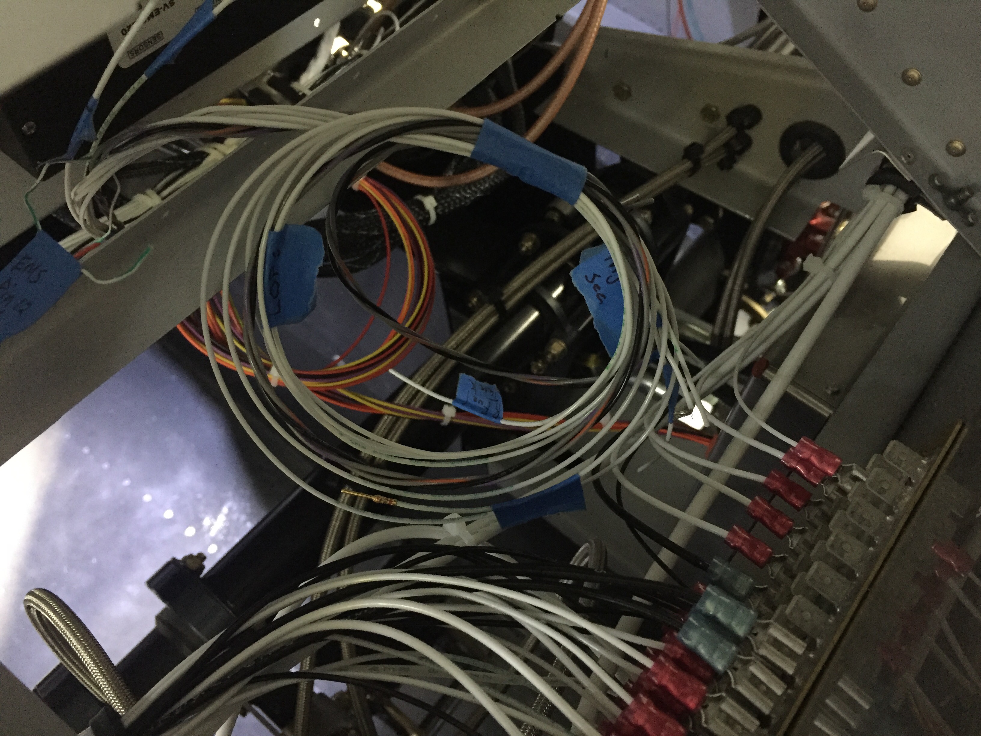
I found that I had a lot of electrical gremlins throughout the first bit of flying. Solder sleeves are amazing little buggers that are notoriously difficult to use correctly. I used sparingly while building, but they still bit me a few times. The problem is you think the solder ring has melted completely but it hasn’t. The connection will be good until it’s subject to some vibration and then all kinds of weird things happen. My oil pressure spiked to 200 PSI, multiple random annunciations based on my discrete inputs, and a few others due to the solder sleeves. And I only have about 10 in the whole plane! I will use them now if I have good access to the connection, but if not, I’ve found using Dsub pins and heat shrink as more reliable.

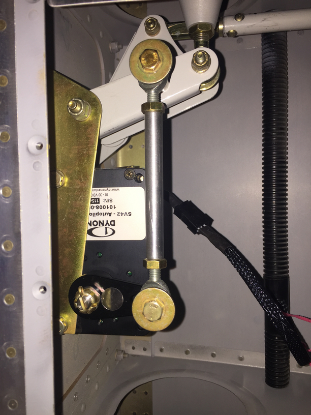
I had to reposition my EGT probes, as I realized they blocked 5 out of 6 spark plugs. I had a master cylinder bolt leaking just a bit. Lots more clamps and zip ties were installed, mostly firewall forward, to avoid chafing after a few oil changes and seeing where things moved a bit too much. I had to replace the autopilot pitch servo due to a service bulletin, roll servo due to slipage, and had to reinforce the rudder trim tab mount to get it to work effectively. I chose to rewire a few engine switches and add a engine master switch, which I should have done in the first place. That all neccessitated under the panel work, a new switch panel overlay and backlight sheet. The oxygen system leaked above 1200 psi (loose connection), and a few adjustments to the door light switches have been made.
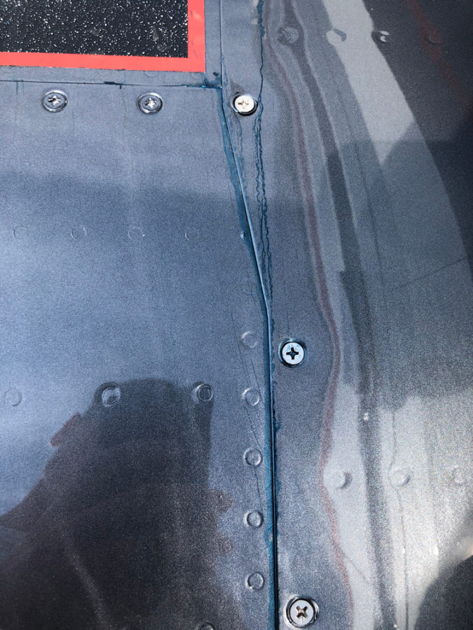
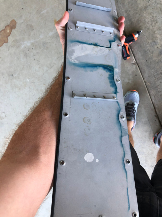
The biggest squawk is a leaking fuel tank. I am getting ahead of myself on the blog, but this was discovered post paint unfortunately. Turns out a little weeping rivet that I discovered prior to paint and thought I had fixed with the Loctite trick wasn’t fixed. In fact, it wasn’t a weeping rivet, but a pinhole in the sealant on the rear baffle. Fortunately, I spent an entire day and was able to use my borescope to provide a view and a coat hanger/tube of pro seal to apply sealant and fix the leak without taking the tank off. Not a fun job.
The engine ECU tweaks were pretty easy, although I’ve gone through four O2 sensors (leaded fuel doesn’t make them last long). I removed the air filters and just installed a mesh screen over the intakes. Speaking of intakes, one was too close to the exhaust header and a hole burned through it so that required a bit of glass work along with better heat insulation and a bit more clearance.

Lots of other tweaks and adjustments were made and most of these delayed discrepancies were taken care of during the first condition inspection performed in November last year. I do have a few more items to check off the list including new door hing covers, some finish rework on the interior windshield pillars, an intake plenum on the air conditioning condensor (more on that later), and adding a second tunnel access plate are all on the list for 2021.

Bottom line, you’re not done building when you’re done building. Flying brings on new stuff that you can’t forecast on the ground so it’s a continuous process to keep it in tip top shape. I also put some of this stuff off, as I wanted to get it flying so its been a challenge to get caught up after flying so much. I am now at a point where the regular maintenance time is decreasing vs the flight time increasing. The check boxes are all most all filled in!

Never ending squawk list

The airworthiness inspection is rapidly approaching and it’s crunch time now. This post is about as fast and deep as all the stuff I had to do.

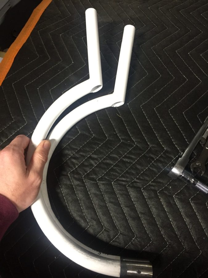
The awesome guys on based helped me bend my control sticks to provide plenty of clearance to the instrument panel. I still hit the flap switch in the full nose down, right roll position, but if I ever have to use that stick input, I have way more concerns about dying.

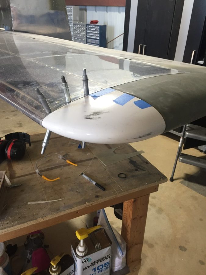
I never installed the tips on the stabilizers, so I wiped the decade old dust off of those and riveted them on then laid up some glass to enclose them. Some tweaking with the heat gun was enough to get them adequate clearance and I’ll let Jonathan do the rest of beautifying them during paint.

I crawled in the tail cone. Again. After I said, “Oh, I’m done back there, I won’t need to get back there.” Hell, at this point I can’t even remember why I had to go back there. I’ll flash forward and tell you that still wasn’t the last time. Either way, here’s how I feel about doing that little shit job.

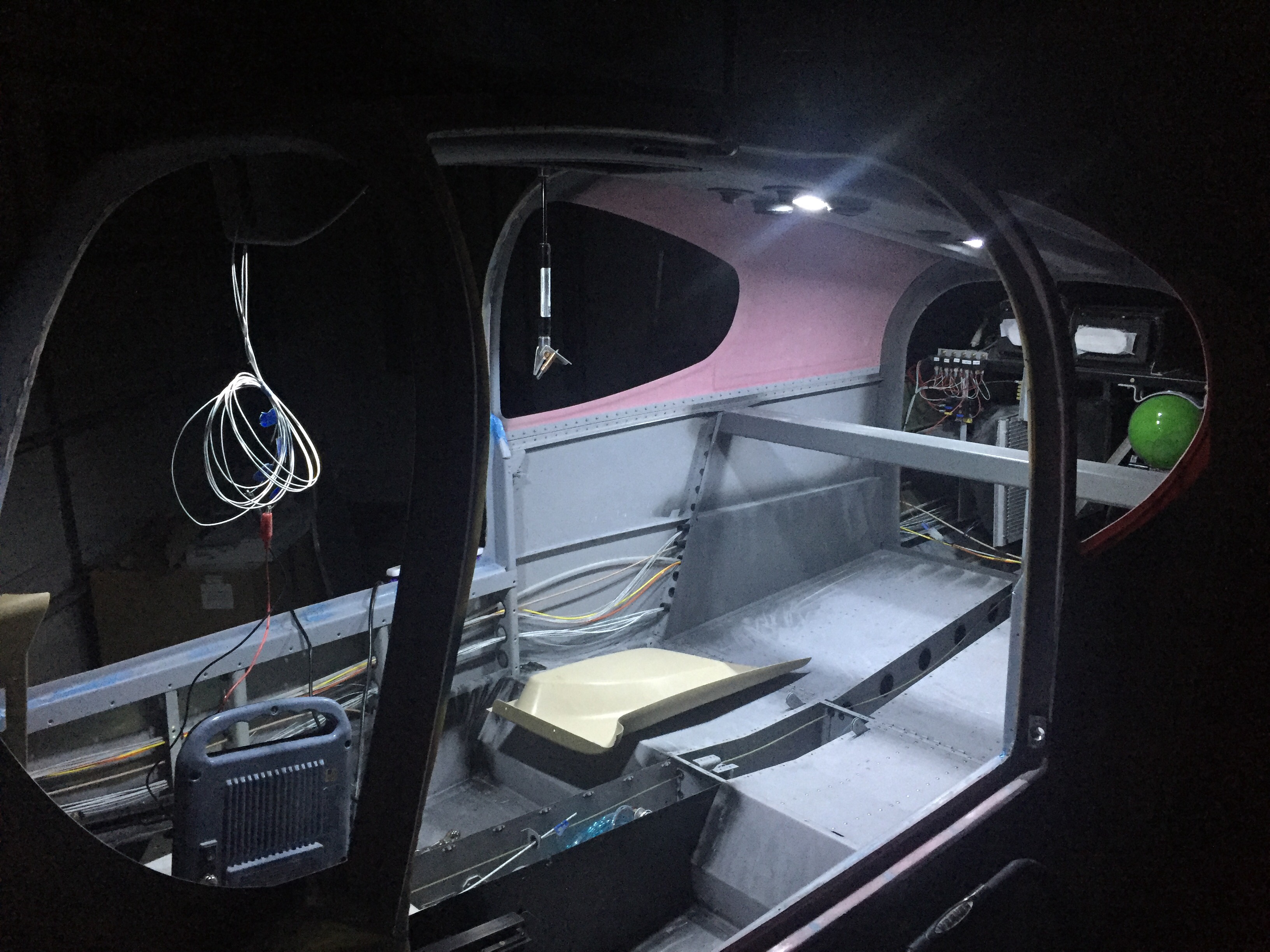
The rest of the interior went in and lights hooked up. These side panels are pretty tricky to slide in without destroying the paint. I’m happy with how they turned out. The stainless screws also look really nice.

I pulled the plane out for a good GPS and comm check. I’ll have another post about the details, but while everything worked, I have some serious interference with the ZipTip lights and my radios. For now, though, no night flying means I’m safe and legal to fly.

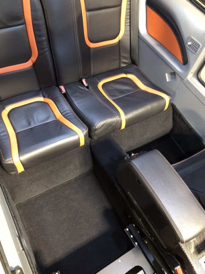
The back seats and carpet are all in now. I had to put a lot of velcro down but man, this Aerosport stuff is amazing. The seats are comfortable, the carpet looks great, and I’m really excited about taking folks flying in this plane!
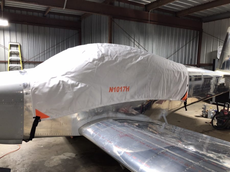
My cover from Bruce’s came in and is freaking sweet. Fits very nicely, has orange, and the tail number embroidered on it makes it so no one can steal it and use it on their plane without me chasing them down.

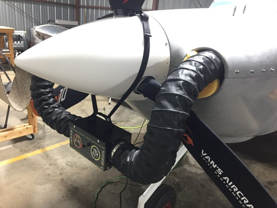
I put the cowling on for a final fit check and hooked up the new AeroTherm engine heater. I’ve used these on the Diamond we fly and really like it. I didn’t like the idea of cylinder heaters and want to keep the engine heated during the winter to avoid cold starts. I know this isn’t as portable, but I’m happy with it thus far. I did have to get a very thick extension cord so it would keep tripping its internal breaker with my crappy 15 amp service in the hangar.

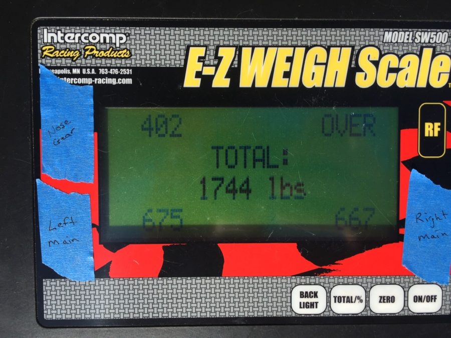
Finally, I weighed the fat little piggy with all of the pants and random stuff not yet on for good in their approximate place. Folks, with full interior, oxygen, air conditioning, three screens up front, and all the extras my credit rating could buy, I’m pretty happy with her girlish figure. This let me sit down and compute weight and CG figures as well. Everything turned out nicely with an empty CG of 106.4 inches.

Splash of color and an Oops

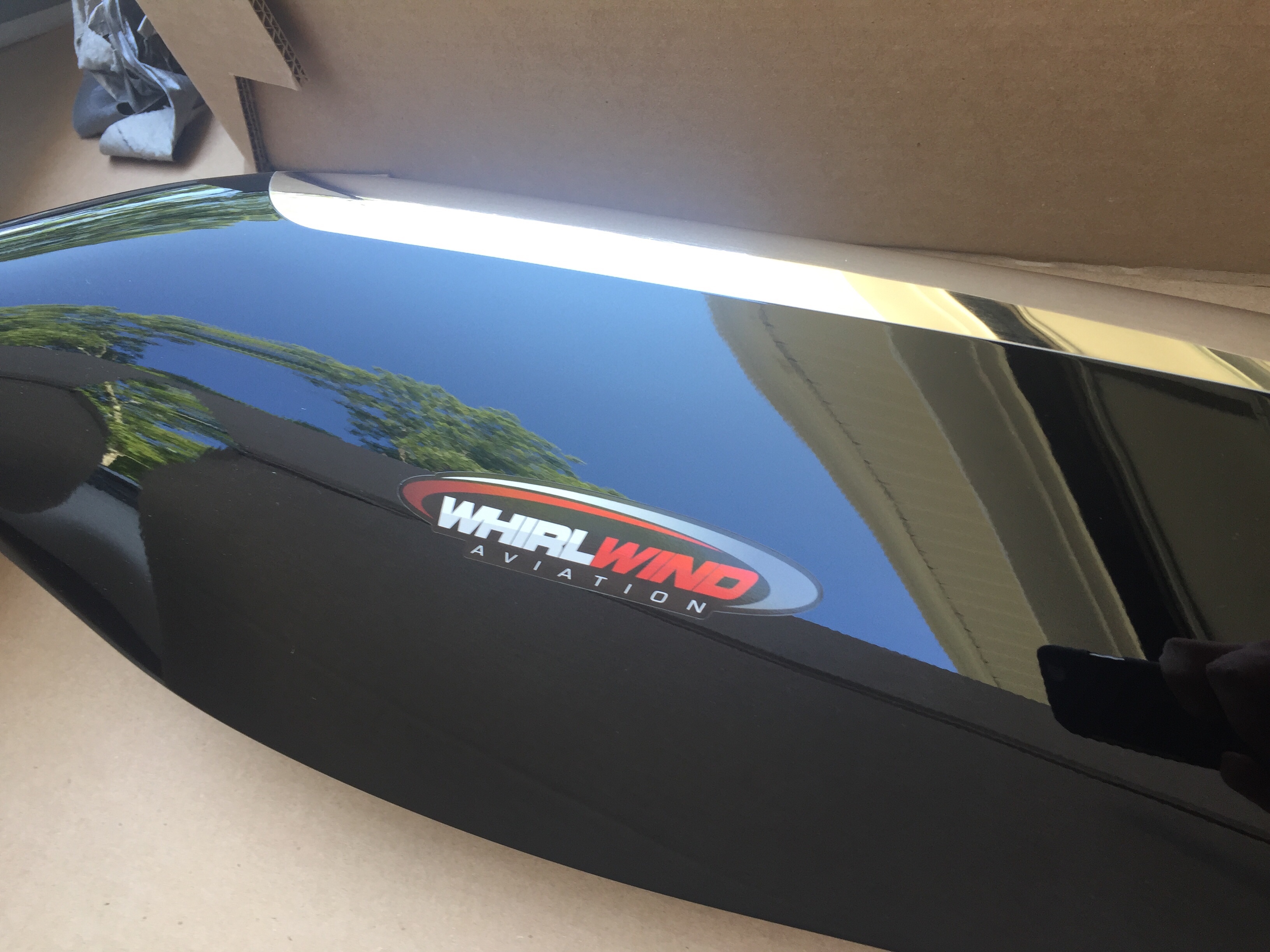
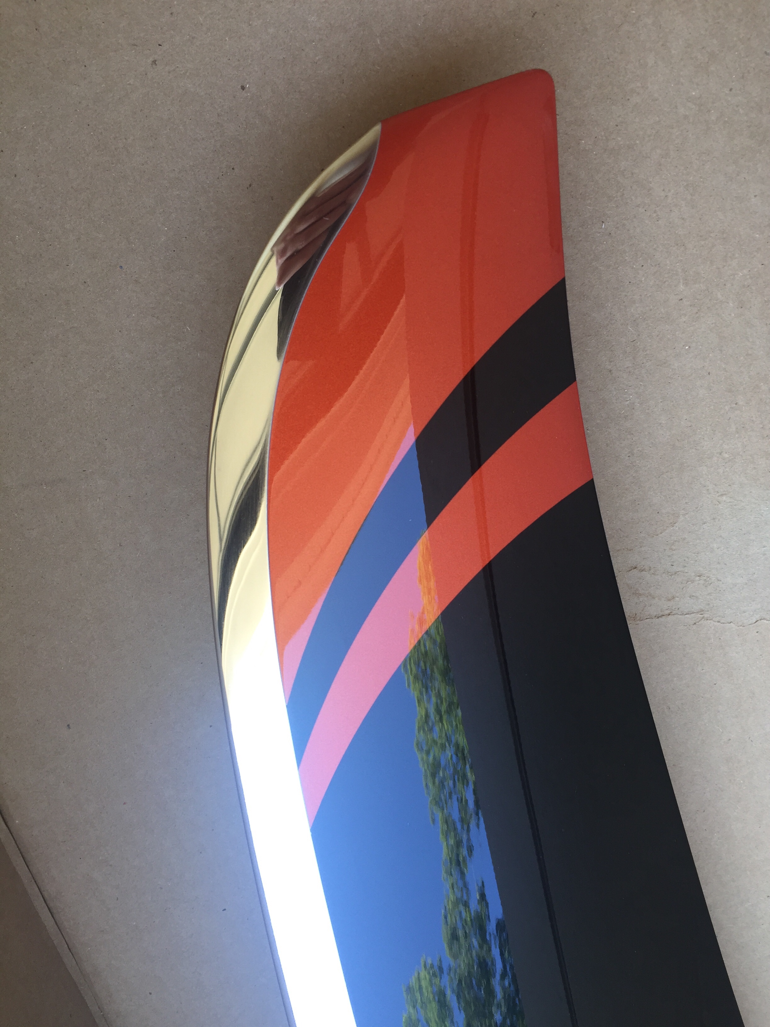
After returning from our trip up north, only a few days passed until we received a big package with a piece of art inside.  Our (second) propeller has arrived!  Whirl Wind delivered about a week late, but with prior coordination and communication with me so I was super excited to see what it looked like.  As chronicled earlier in the build, I purchased a propeller but decided to sell it instead of it hanging on the wall for three years before I was ready for it.  Joe Keys, you can’t have this one.  I knew I wanted another WW and the HRT blade is now a refined blade profile and is simply stunning.  Our orange was color matched and looks great with the black and nickel leading edge.  For now, the prop will go to a friend’s hangar to hang out with the wings until we move to the airport.

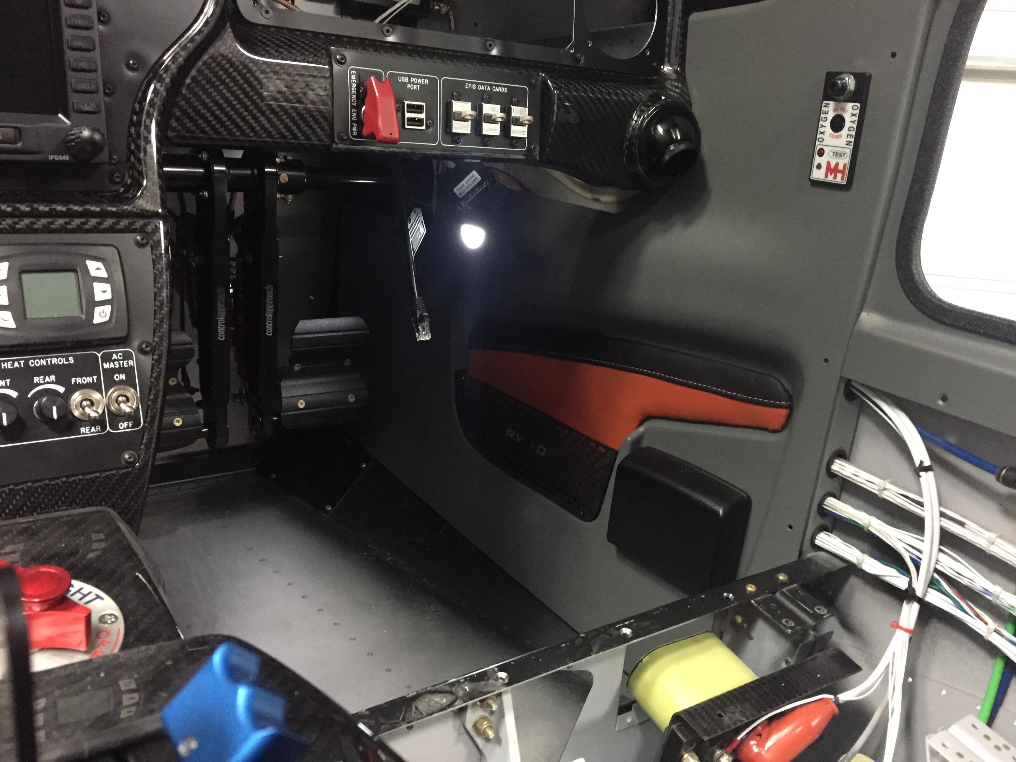
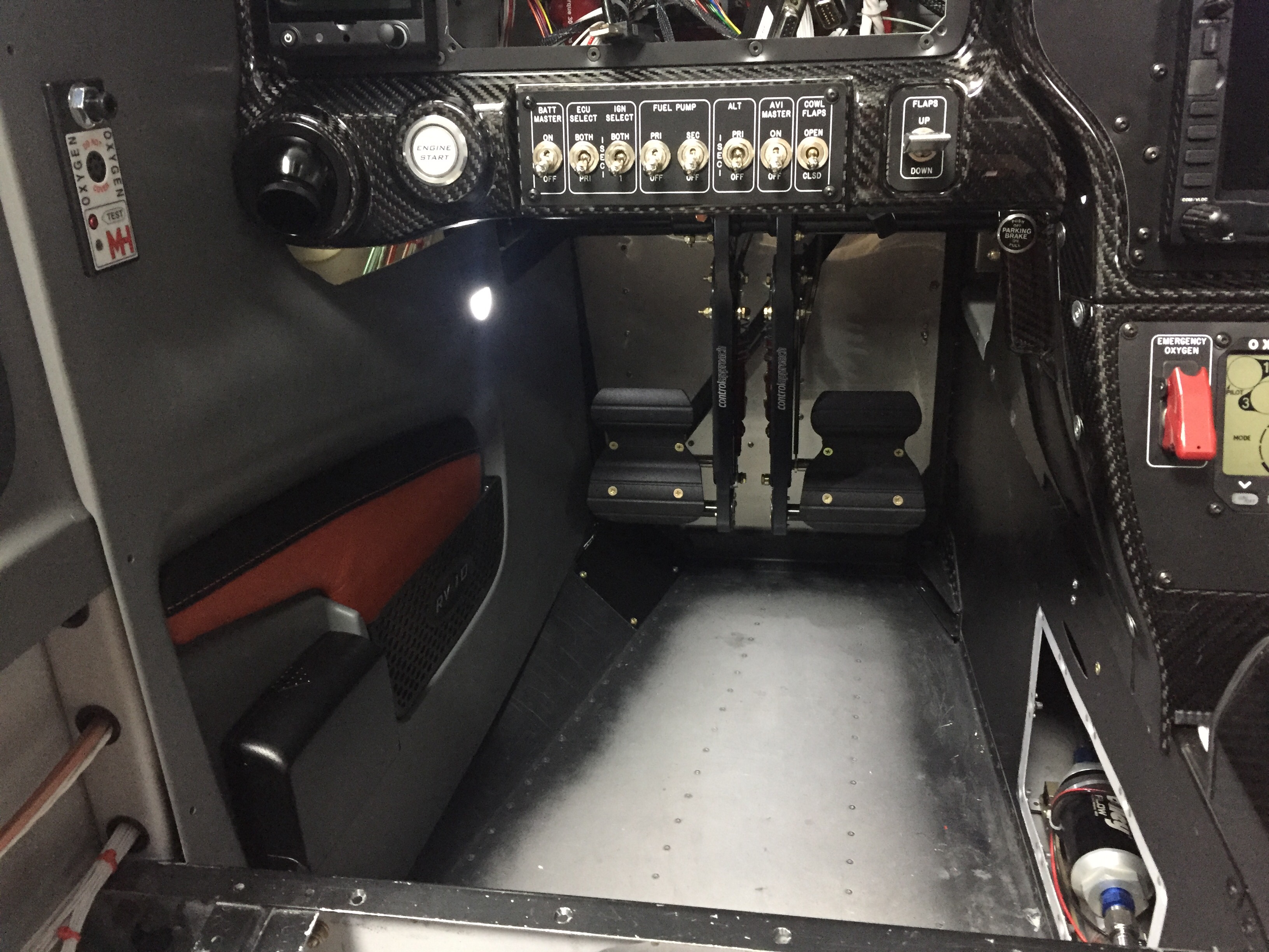
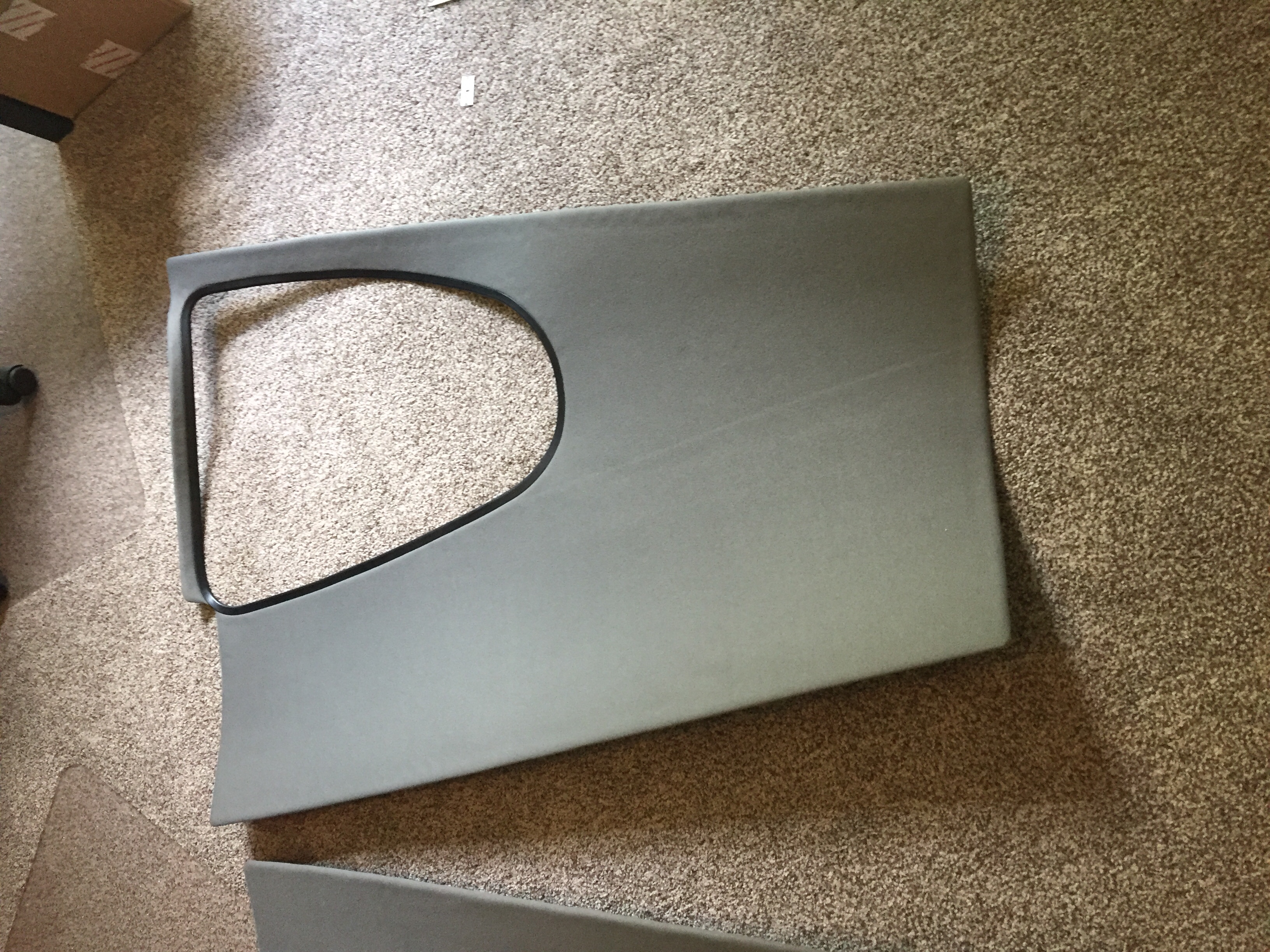
Adding even more color, I finished up the last of the wire bundling on the cabin sidewalls and went ahead installing the side panels with leather inserts.  They had been trimmed and painted for some time but I held off pulling them in and out until I knew I was done.  I spoke to Vic Syracuse who will be my DAR for airworthiness inspection prior to putting these in, as I wasn’t sure how open he wanted the airplane.  He advised to have it essentially flight ready except for rear pax tunnel cover (to inspect the elevator bell crank), cowling, and tunnel access panel.  This is the first time I’ve hooked up the foot well lights and I’m really pleased with the amount of light they give off.  It’s just enough for convenience while not quite enough to perform surgery on the floorboard.

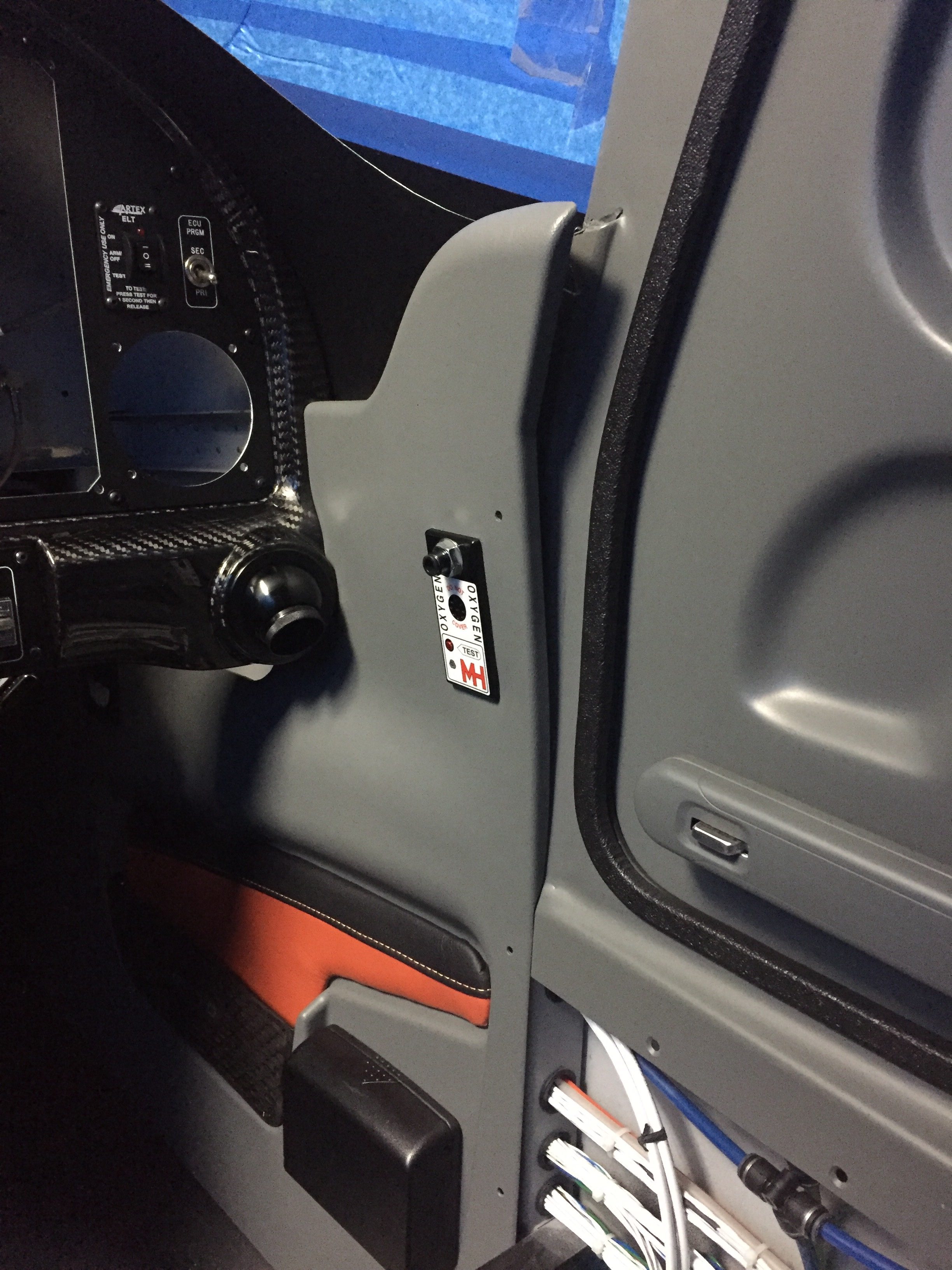
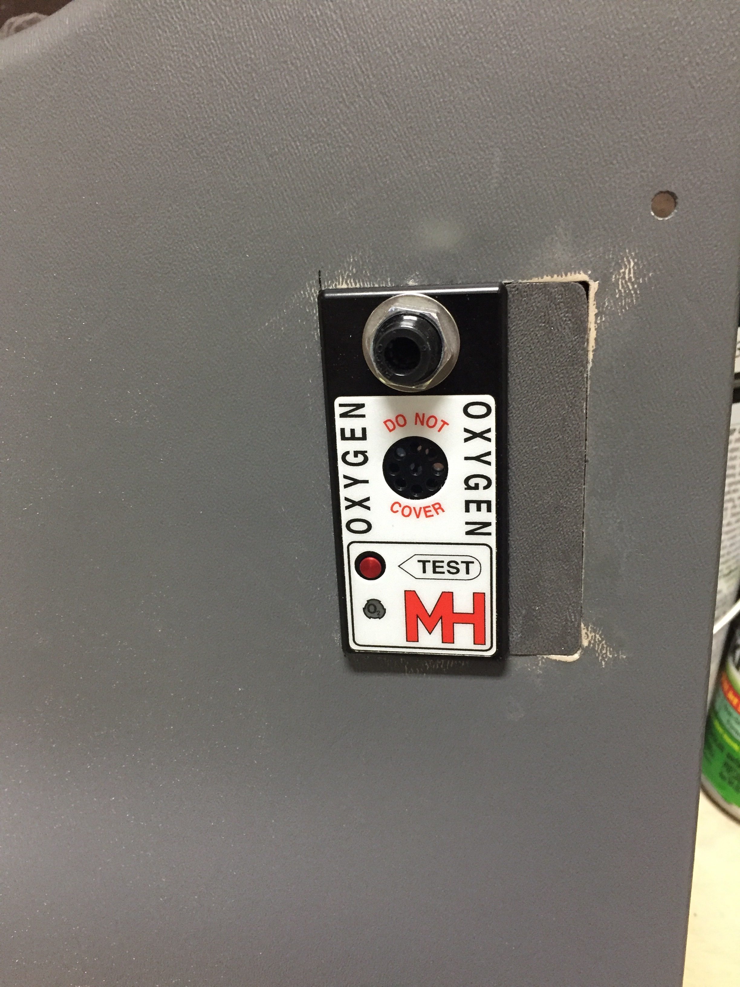
Unfortunately, not all of the gods were looking favorably upon this new addition and when I closed the door, the pins interfered with the oxygen ports, thus not allowing the doors to latch properly.  Turns out I have the ports ½” too close to the door frame.  Darn.  Well, I said, a lot more than that and maybe one or tools took flight across the garage with no lasting damage.  My blood pressure through the roof due to my ignorance and stupidity of not being mindful to this interference, I weighed the options of replacing $500 panels or coming up with a patch.  I can’t make the pins shorter since they wouldn’t function correctly with the Plane Around latch mechanism.  I had already had to glue a piece on the pilot side panel and reinforce it with a bit of epoxy.  The seam was easily hidden and paint covered everything, so I was hopeful I could repeat the process.  A call to Will at Aerosport Products equaled a few scrap pieces of plastic heading my way.  An evening of creating two patches and a bit of filler, and I’m back on track.  If you look close enough to tell the patch is there, you probably won’t be flying in my airplane again; kindly go away and take your judgement with you.

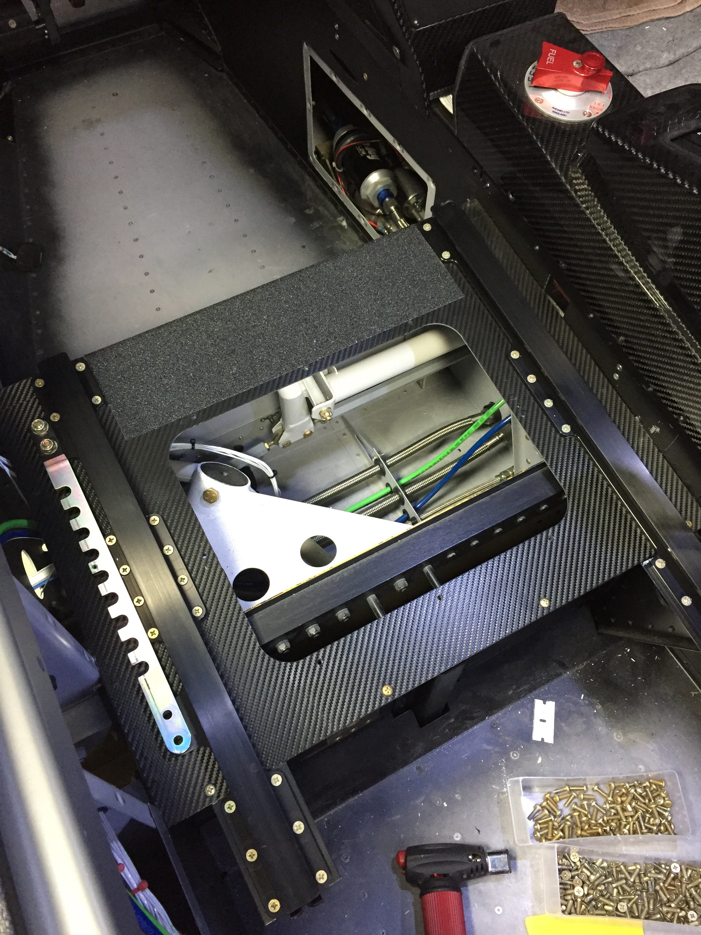
Meanwhile, I applied the 3M carbon vinyl wrap on the seat pans to clean those up.  I figured out quickly paint was not going to hold up there.  Brian and Brandi had great results with the wrap material, so I figured it’s worth a shot.  I then put a strip of anti-skid tape to facilitate stepping on the seat ledge while getting in and out.  It really cleaned up the area nicely.  I also shimmed the outboard pilot seat rail, as the bracket above the gear mount was a 1/8” proud causing the rail to bend when screwed in.  Not sure what happened there, but with a few washers underneath it’s nice and straight and secure.

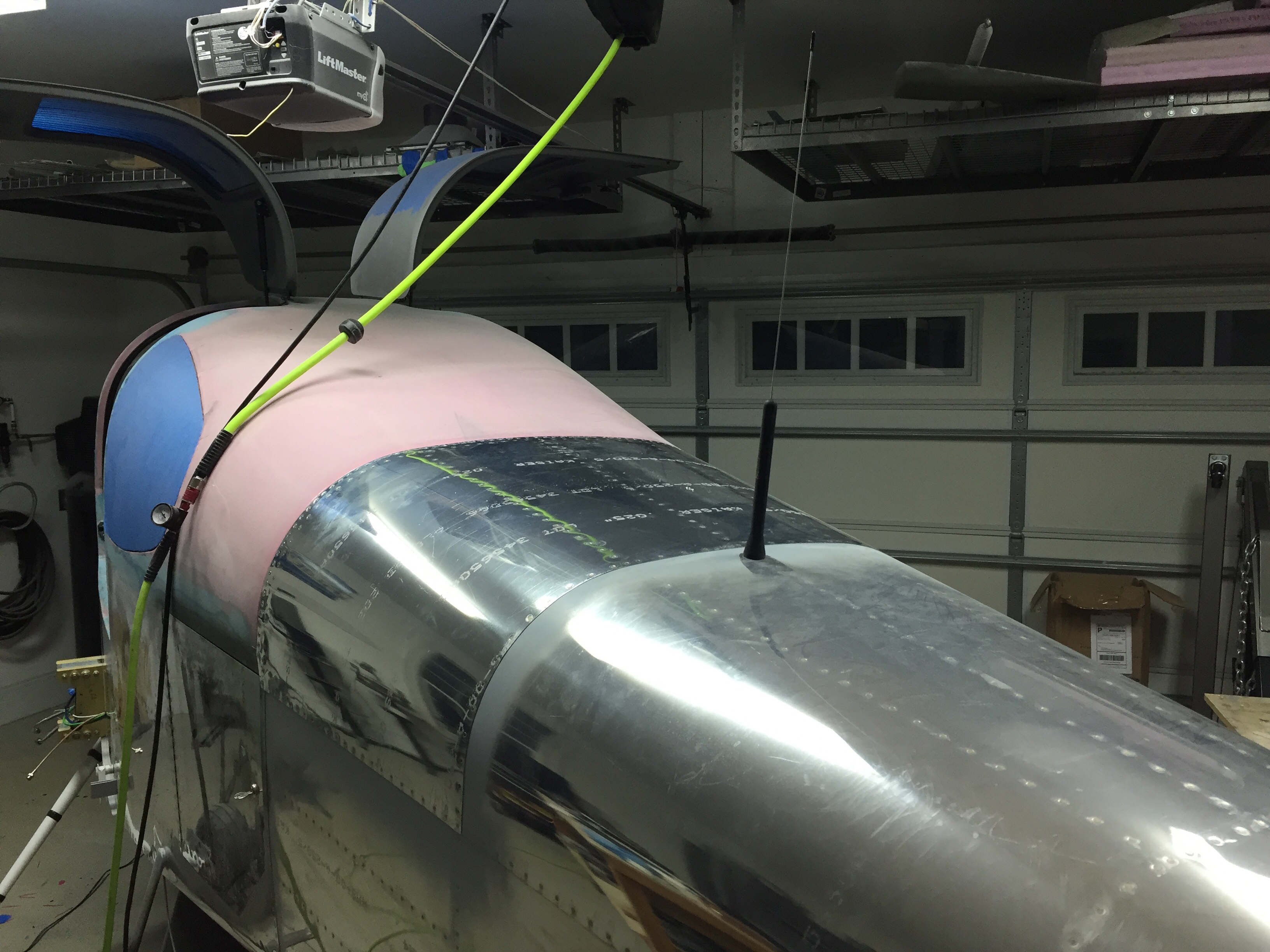
I quit trying to cheat the system and installed the ELT antenna on the top of the tail cone.  I tried every which way to hid that hideous monstrosity of an antenna but my conscious told me that it is probably the most important antenna on the airplane thus deserved its place per the install manual.  I’m sure it will grow on me.  The idea of burying it in the tail cone or tail fairing was tempting, but a talk with my DAR convinced me otherwise.

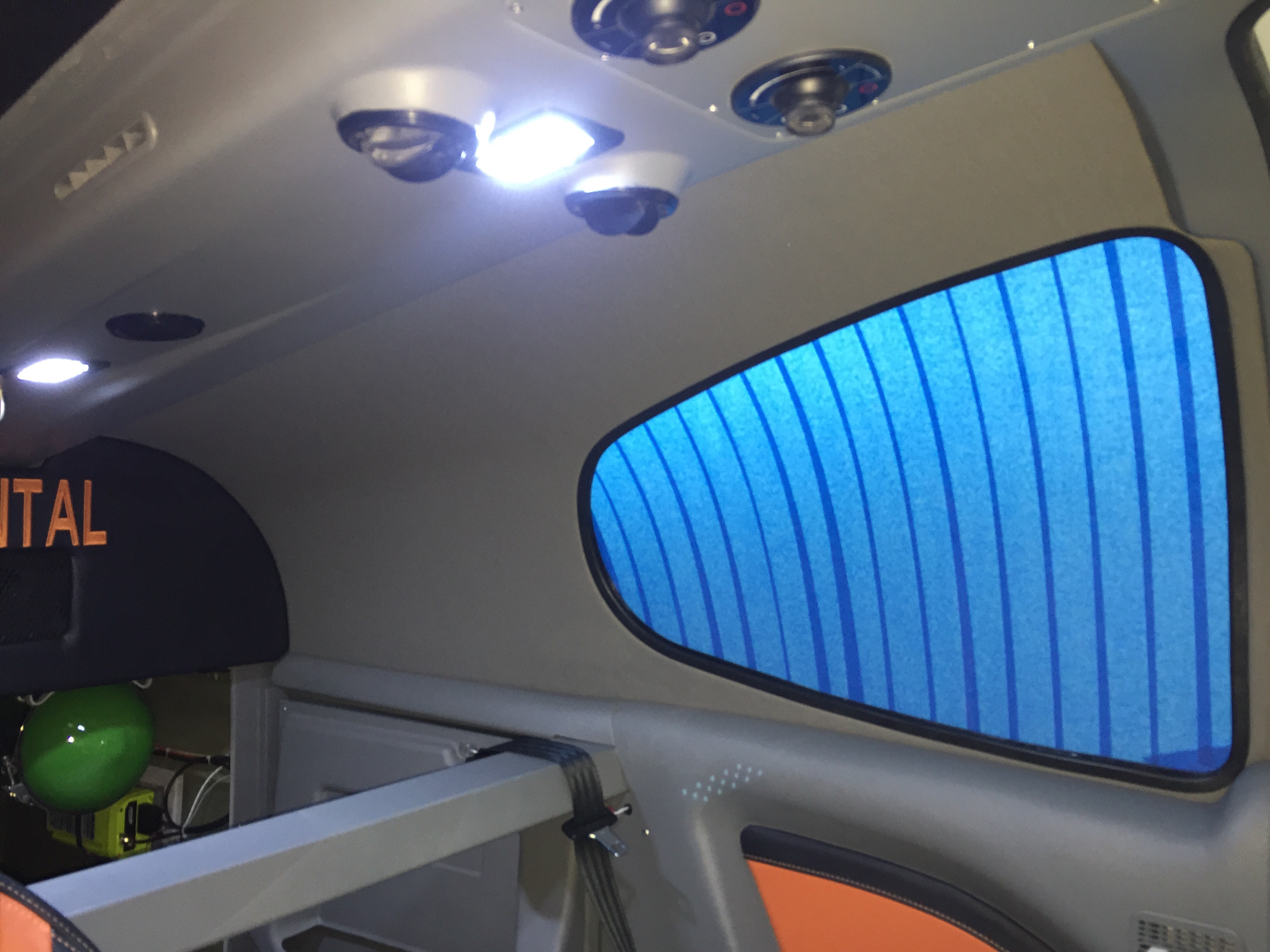
Continuing in the cabin, I spent an afternoon applying the headliner material to the fiberglass shells from Aerosport that had been trimmed for quite a while now.  It was a bit of a messy job with the spray adhesive, but not difficult at all.  I took my time and kept my fingers clean which resulted in a darn near perfect result.  After putting enough Velcro to hold a car upside down, the headliners slid into place and really dress up the cabin cover now.  The color matches great and was overall a lot easier than trying to smooth and paint the cabin top itself.

Finally, the rear bulkhead cover was back from Aerosport with the matching leather and embroidery.  I used Velcro to mount it to the bulkhead panel after installing a grill for the air conditioning return.  It turned out great and I’m really pleased with the fit and finish once it was all installed.  The cabin is really coming together with the rest of the rear side panels installed and inserts in place.  It’s tempting to put the carpet and seats in, but I’m holding off to keep them in good shape and clean while I finish building.

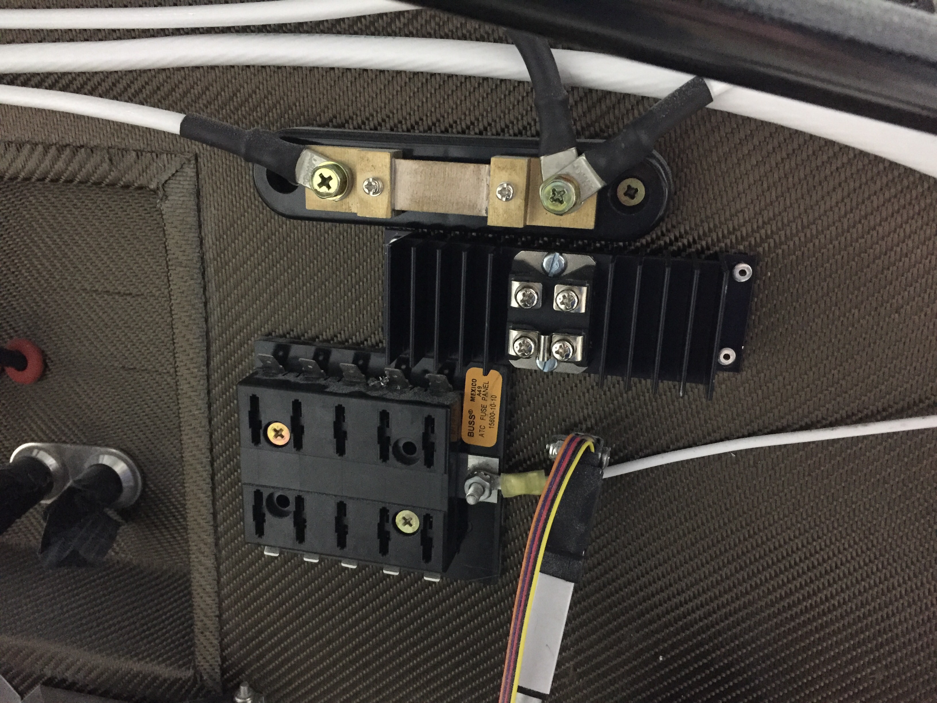
Upfront, I had an epiphany about my shotky diode and how it should be used to protect my engine bus.  The goal was to isolate the engine bus from the rest of the system such that I can turn the emergency power switch on (direct connection from battery to engine bus) and not have the electrons go to the man bus.  This essentially covers a short somewhere in the system or electrical fire behind the panel and gives me a bit of redundancy on keeping the electrically dependent engine going.  I wasn’t placing it on the proper power lead on the schematic, so it finally dawned on me it should go from the main power supply instead of the backup lead.  So, I installed it on the firewall and will work on a solid copper bar to hook everything up.

The Magic Smoke

Aircraft avionics are powered by a mystical, magical smoke that is contained inside the fancy boxes and wires that make up the complete system in a little airplane.  This smoke is very precious to an aviator and should not be released out into the atmosphere under any condition.  Once it has escaped, the only way to recapture it is to spend many, many monies soaked in tears.  Therefore, it is imperative that when flipping the master switch on for the first time, all efforts to contain this magical smoke are made to avoid crying and empty bank accounts (again).

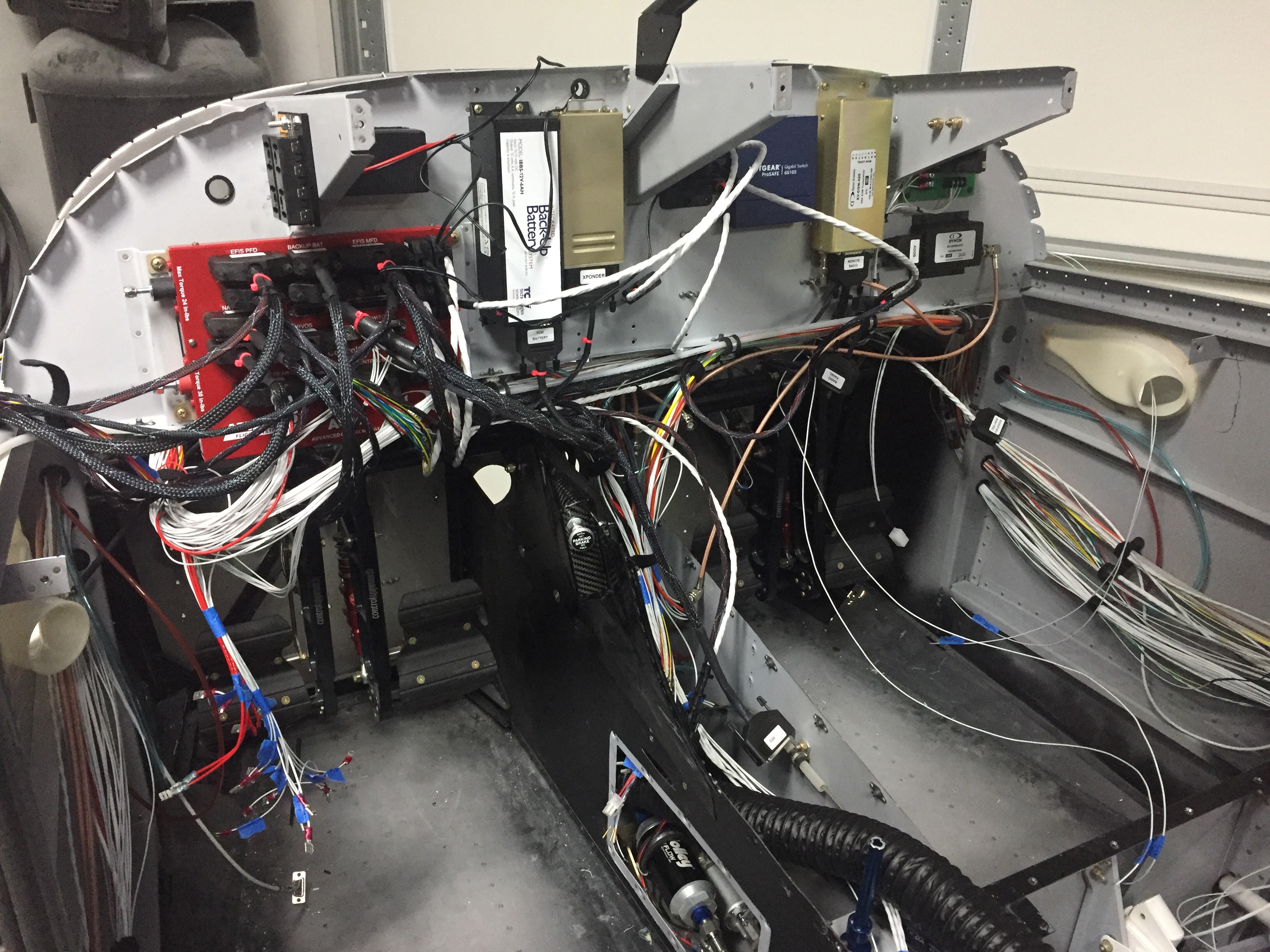
I spent each minute working on the wiring also tracing paths and double checking all of my runs and connections against the wiring schematic, manuals, and common sense.  I also dedicated an entire evening to looking everything over, pulling on connectors to ensure good crimps, tidying up the last little stragglers, and ensuring that all un-terminated wires were in that state for a good reason and properly labeled/protected from short circuiting.

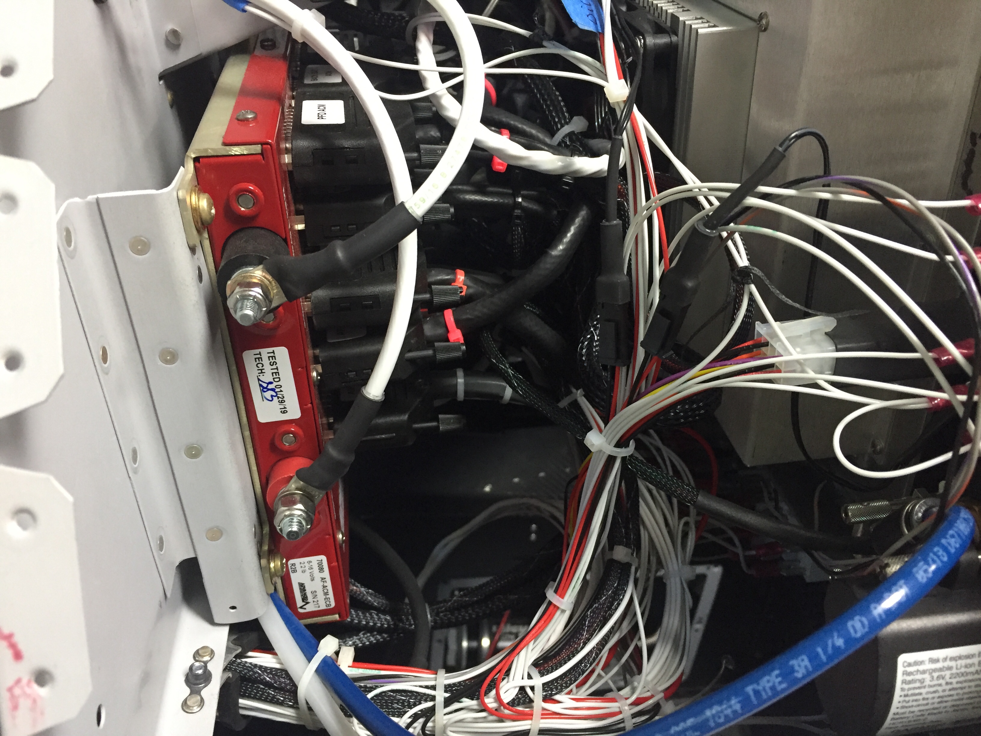
Using the ACM means I can’t just pull all the breakers and turn one on at a time.  Unfortunately, I have to power up the whole system then get a screen going to electronically trip each breaker, by then a little late for an emergency.  I was confident that the expensive bits including screens and components were all fine, as they were bench tested from AFS.  But, there is always a chance that the extra stuff and main power distribution was wrong since I designed and built that.  Looking back, I could have disconnected the power wire to the ACM until after I confirmed the main distribution system worked, but I’m jumping ahead.

At long last, I ran out of excuses to delay the inevitable and decided tonight was the night to flip the switch and see what I had.  The plan was to have Laura help me monitor the plane and keep an eye out for that magic smoke.  I walked her through the plan to quickly flip the switch on and off, we talked about what we’d expect to hear and see, and the worst case scenario of a big spark or smoke.

I held my breath and flipped the master switch on and then quickly off, just as briefed.  We didn’t hear any notice, no clunk of the contactor, no fans, no screens flickering or anything.  Hmmmm.  Laura said maybe the flip was too fast.  Good point, maybe so.  Okay, I’ll try again for 1 second and then turn off for good if nothing powers on.  Master switch on……..

PPPPPPpppppppsssssssssssffffffffffftttttttt goes smoke!!!!!!

I heard it before I saw it.  None of the counseling says you hear the smoke before you see it and it made the experience that much more traumatic.  But as promised, a small, thick stream of the magic floated from the firewall towards the ceiling laughing at me and my meager attempt to contain it.  Well shit.

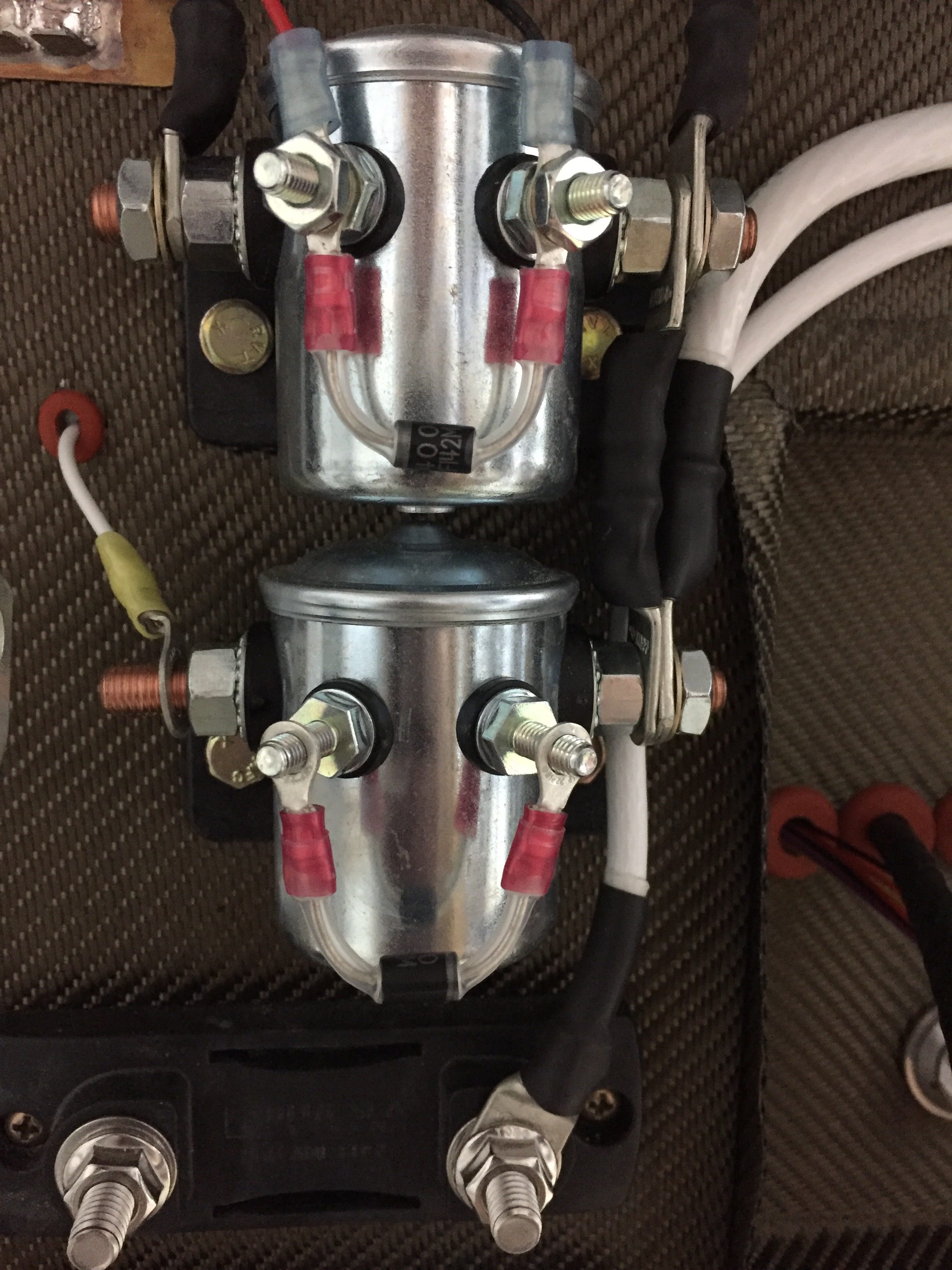
Needless to say, I flipped the switch off as soon as I heard/saw the smoke and quickly went into problem solving mode.  First question, what smoked?  It was pretty obvious from the melted dripping insulation the jumper wire on the main contactor had rode the lightning.  It connects the coil terminal to the hot terminal.  But why?

Take a look at the picture below and tell me where Waldo is.  The top contactor is the ground power receptacle contactor which is not hooked up at the time.  The bottom contactor is the master.

Did you notice the diodes?  Well good for you know it all smarty pants.  I sure as hell didn’t.  And why would I?  These came from B&C right out of the box!  It turns out the diode on the master contactor was installed by B&C backwards, essentially allowing a short to ground to happen when I turned the master switch on.  Power went through the diode the wrong way, through the switch, to ground and fortunately the jumper wire was the thinnest gauge so acted as a fuse and burned.  Since the power went the wrong direction, the contactor never closed and no power was delivered to the aircraft.

After confirming with Parish, I canned (cannibalized) the diode from the GPU contactor and installed a new jumper on the master to repeat the power on test.  I confirmed the polarity of the diode, checked continuity and voltage on all connections again, and decided to disconnect the ACM from the firewall pass through, limiting the exposure to the expensive bits until the magic smoke is stuffed back in where it belongs.

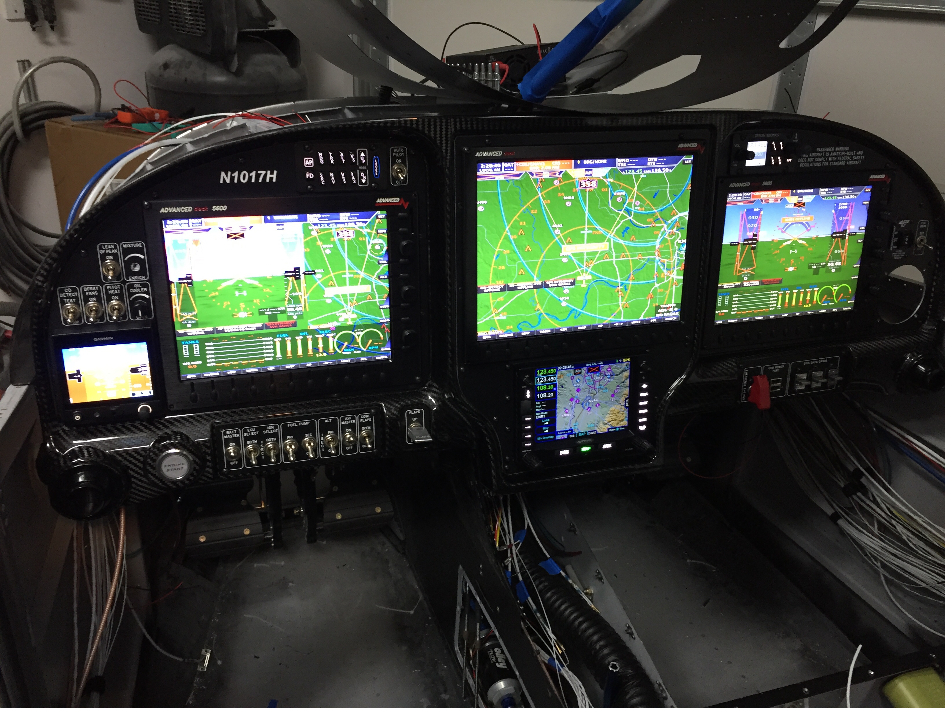
The third time was the charm, and the reassuring clunk of the contactor resulted in no smoke and positive voltage just where it should be.  I connected the ACM wire and saw the screen flicker to life with the AFS logo, what a beautiful sight!!!  I flipped the avionics master on to watch all of the other screens power up and soon we were basking in the warm glow of synthetic vision, calibration warnings, annunciations, and confused maps looking for GPS signals.

Each circuit was tested with the multi-meter or device if it was connected.  Some were just reading voltages, such as lights since the wings aren’t installed yet.  My only squwak was the strobe and nav switch wires being reversed, which I took care of by pulling the overhead panel and making the correction.

I cannot describe the joy of seeing all of this powered up and finally a working product.  I have spent years dreaming of having a setup like I have and a lot of work and money went into getting to this point.  I have a lot to learn, figure out, and get proficient at!  I am so excited to get behind these screens and put them to work on all kinds of adventures.

Most of all, I’m lucky that I only let a little bit of magic smoke escape and was miraculously able to stuff it back in where it belongs!

Let me see that glass

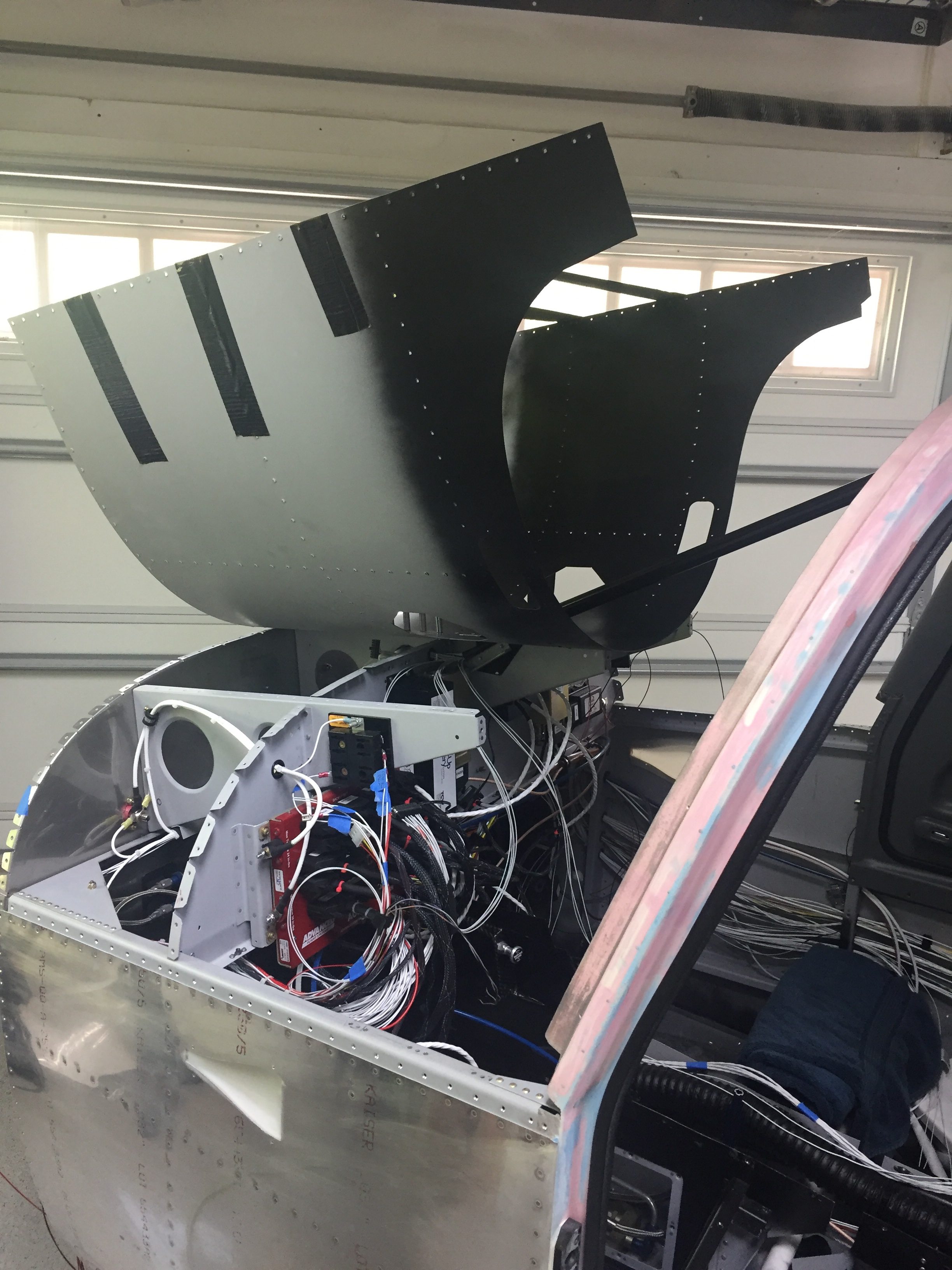
At this point, I’m out of wires to run in the plane and about out of wire from my workbench!  I made the call to rivet in the forward fuselage section structure so that the bundles could be zip-tied and I could move forward with putting the panel and avionics in for good.  (I actually riveted this in before doing the firewall insulation, but it was easier to type in this order.)  As with most big things, it was very anti-climactic and completed in about 15 minutes.

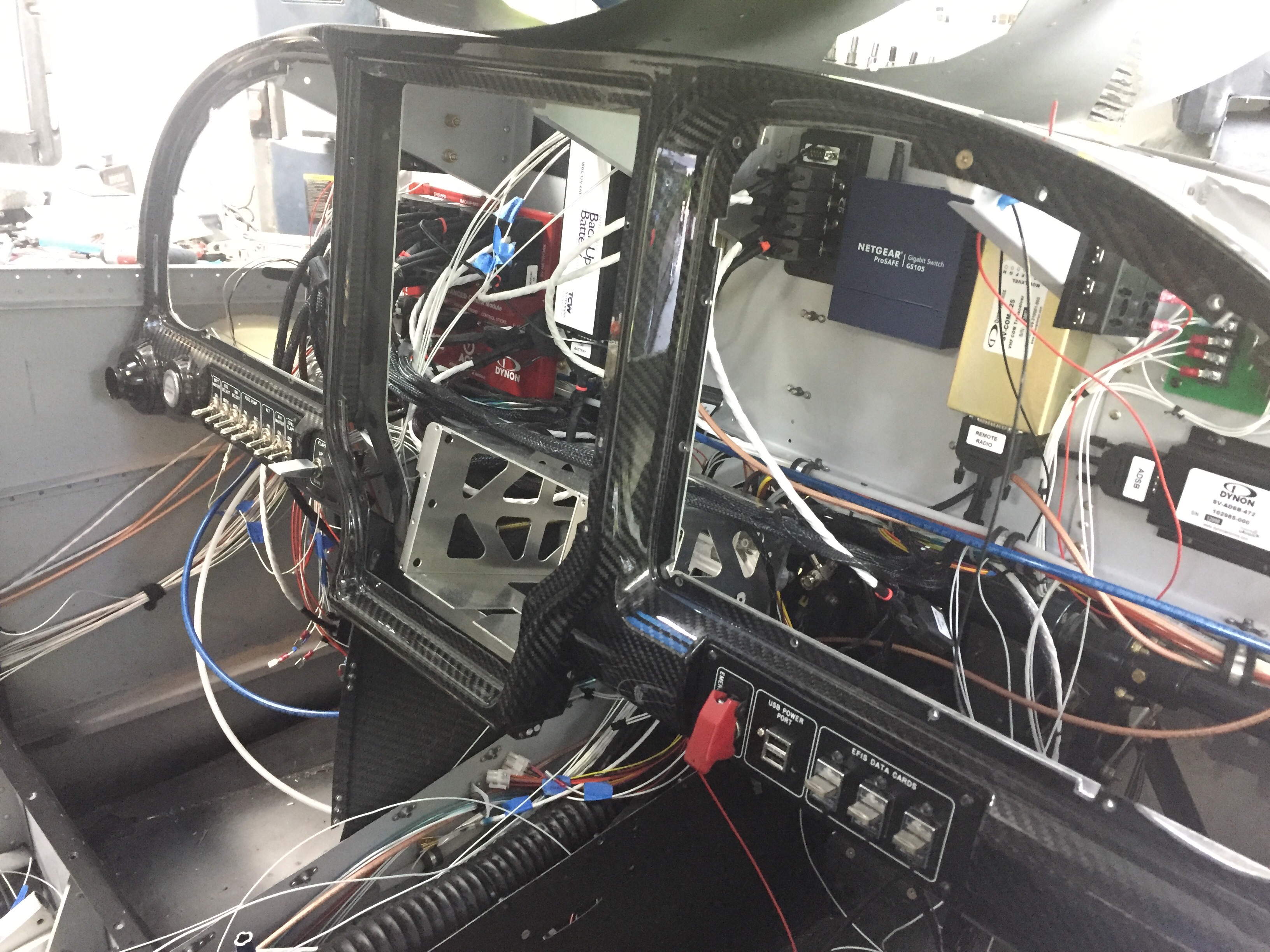
I put the carbon fiber frame and back plate in and got it all screwed together in the right order.  All of the switch panels were hooked up for good and along the way, bundles were tidied up as much as possible.

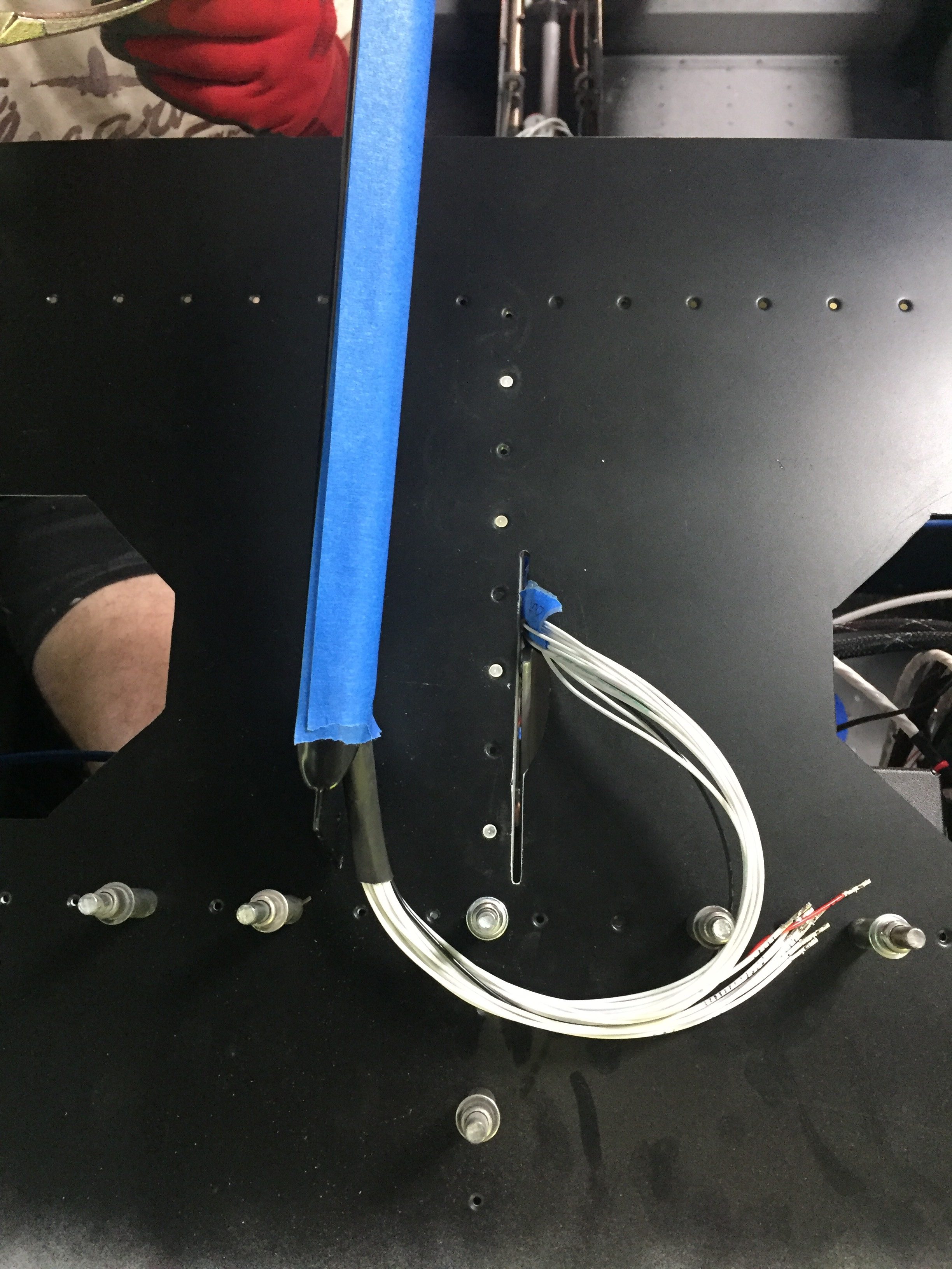
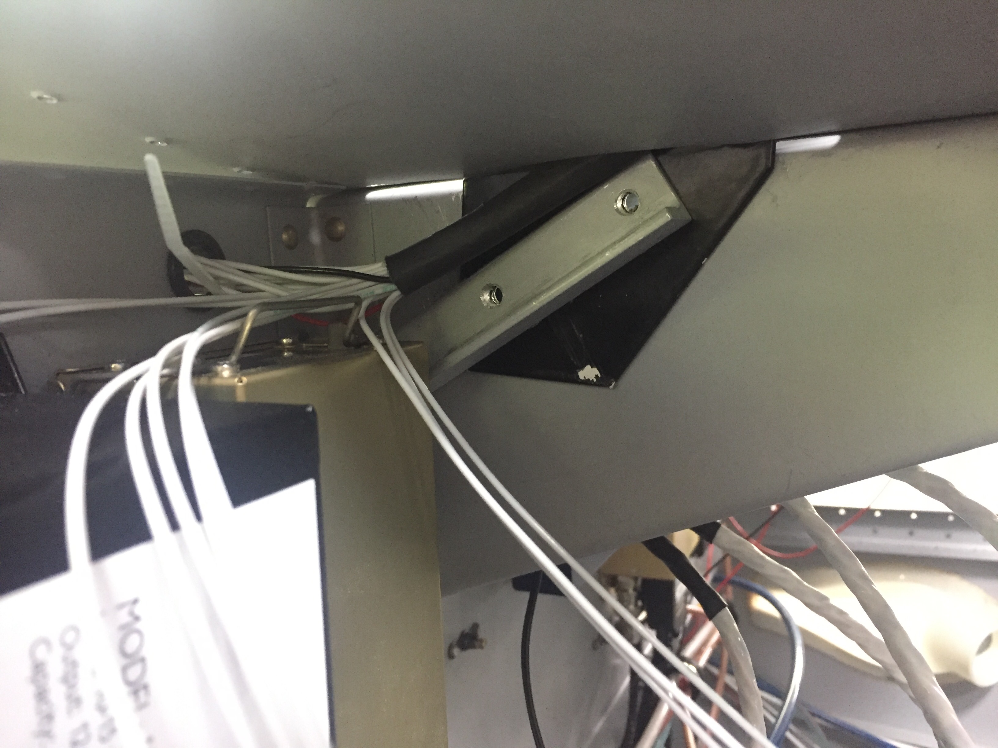
The last major task for wiring was the overhead console and lighting wire run.  The front structure (now in) and skin has to be installed before I can run the wires down the support bar (powder coated black with the engine mount).  I wanted to keep as much access open as I could to finish up the avionics so I worked out a way to bend the skin upwards by riveting the center rivet line only.  Laura came out to work her magic behind the rivet gun and assisted in getting the wires through the bar and the bar installed.  It was a bit tricky feeding everything through the skin but worked out well in the end.  I did elongate the slot in the skin since my overhead switch panel prevents the bar from going in at the bottom first.

I set about connecting the wires from the overhead since I had already pre-routed them and installed terminals as needed since access would be difficult once the forward skin is in place.  Glad I did that, because I could never have pinned them out as they were after the skin and bar were installed.  The back lighting wires were all solder sleeved together to the power supply and the positive wires for the power supply, start switch, and O2 controller back lighting were all ran to the dimmer.  After a lot of observing and double checking, the only wires left unterminated are those going to the EMS/ECUs (I won’t have the ECUs until July) so nothing left other than starting to test stuff out!

The lighting control module (LCM) and instrument back lighting will be on the always hot bus so I was able to hook my bench power supply up to test it.  I was pretty nervous as there are a lot of complicated wires on the LCM and I was afraid of knowing where or how to troubleshoot an issue.  I shut the doors, turned on power and held my breath.  Opening the door should have turned all the lights on but it just made them flash.  The foot well dimmer was hooked up to the overhead and the back lighting didn’t work at all.  Fan-f**king-tastic.  Great start, Tim.

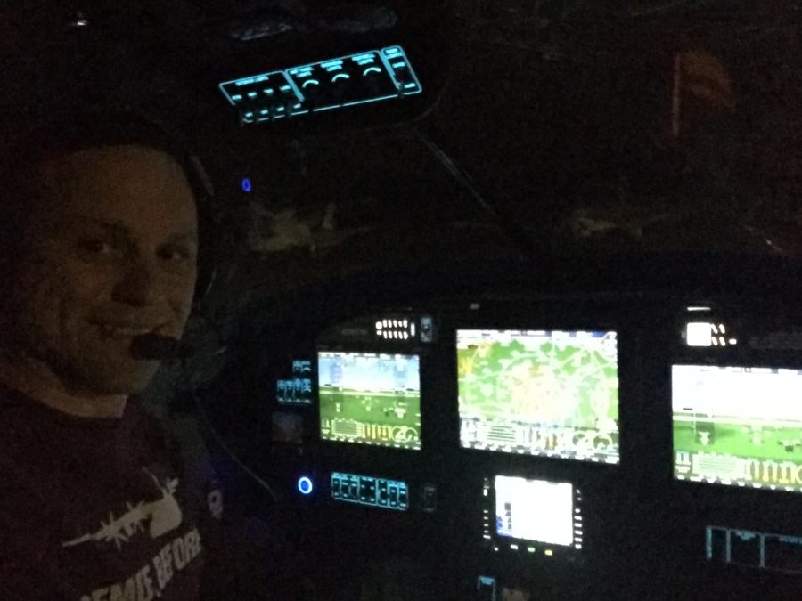
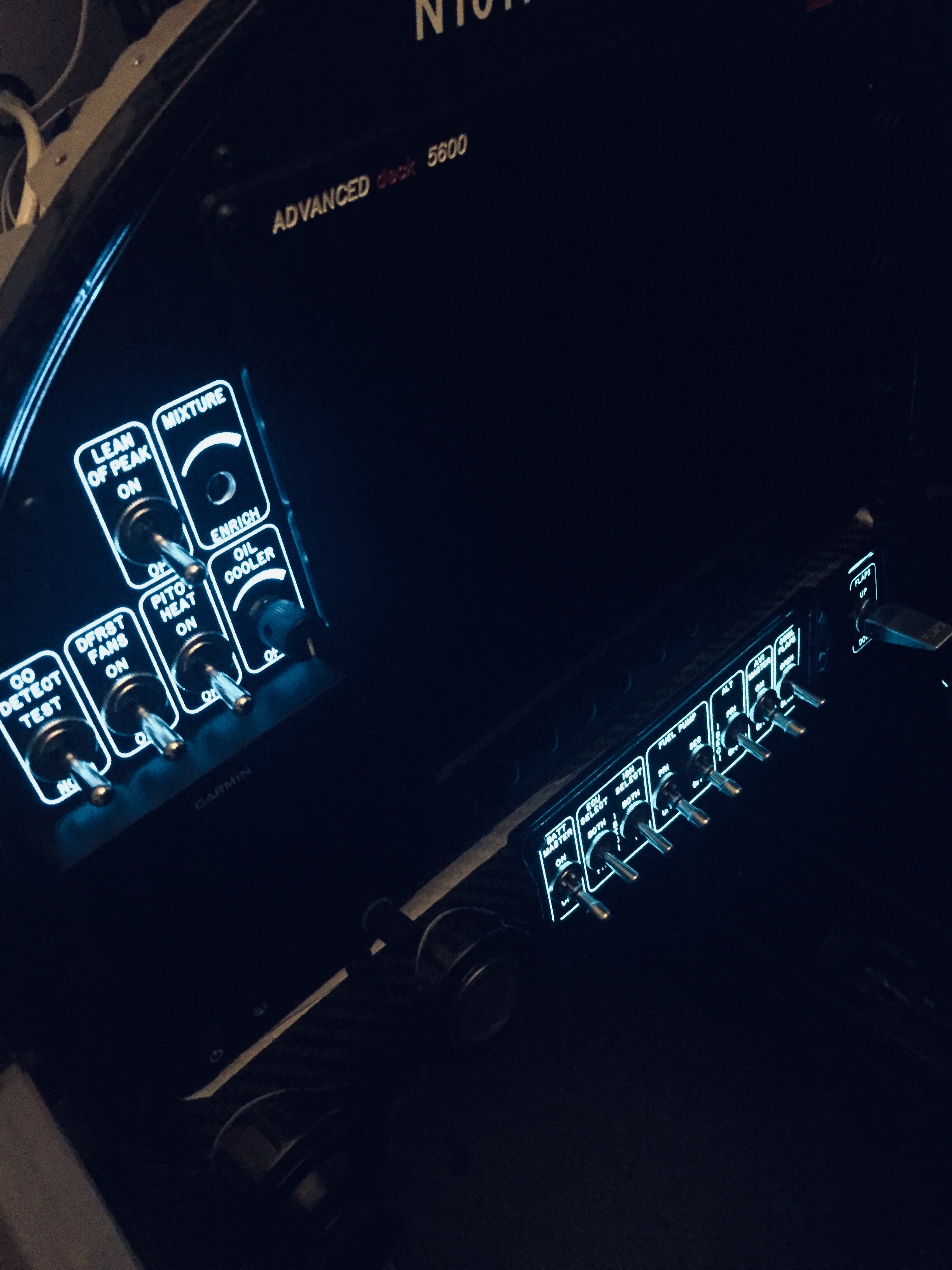
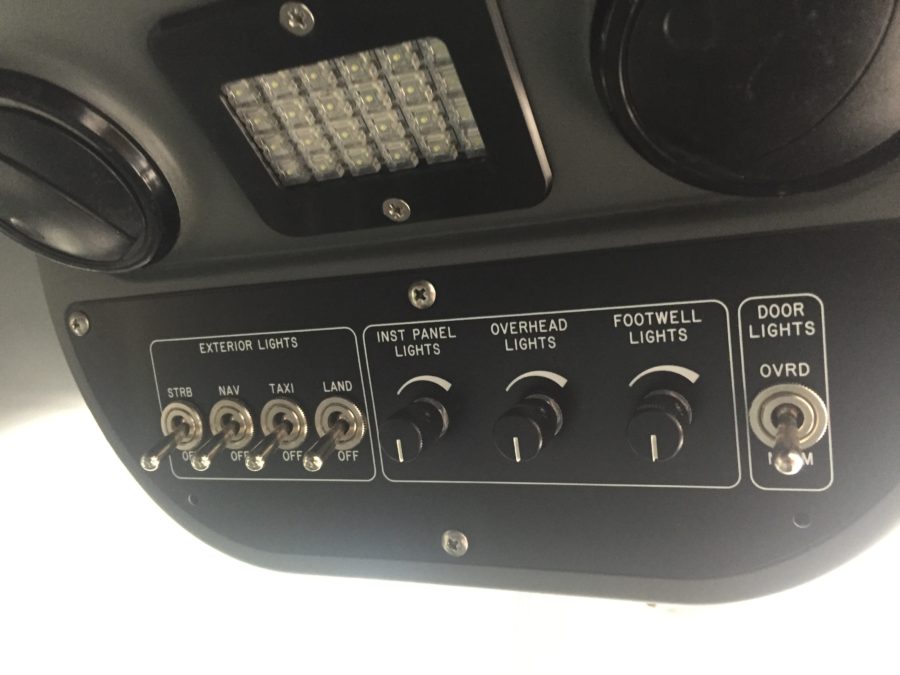
My skills at troubleshooting are more advanced than my confidence, and I was able to correct the wiring on the dimmer module (I had mislabeled the potentiometers) and figure out the back light power supply had a solder sleeve that didn’t solder all the way causing a bad connection.  Those were corrected and I had two out of three working.  The back lighting looks magical (yes, I said magical) and I sat in the dark for five minutes ooohing and ahhhing at myself.  The overhead dimmer and foot well dimmer circuits were now working and I could see how well Sean’s (Plane Around) LEDs illuminate the cabin.  The door lights and switches were still not working, though.  As soon as the door opens, I could hear the relay click causing the lights to turn off.  It turns out I had added an extra ground to the override switch and it was immediately overriding the timer in the LCM.  I corrected that and at the end of the evening got to see the fruits of my labor on the LCM as everything worked exactly like it should!

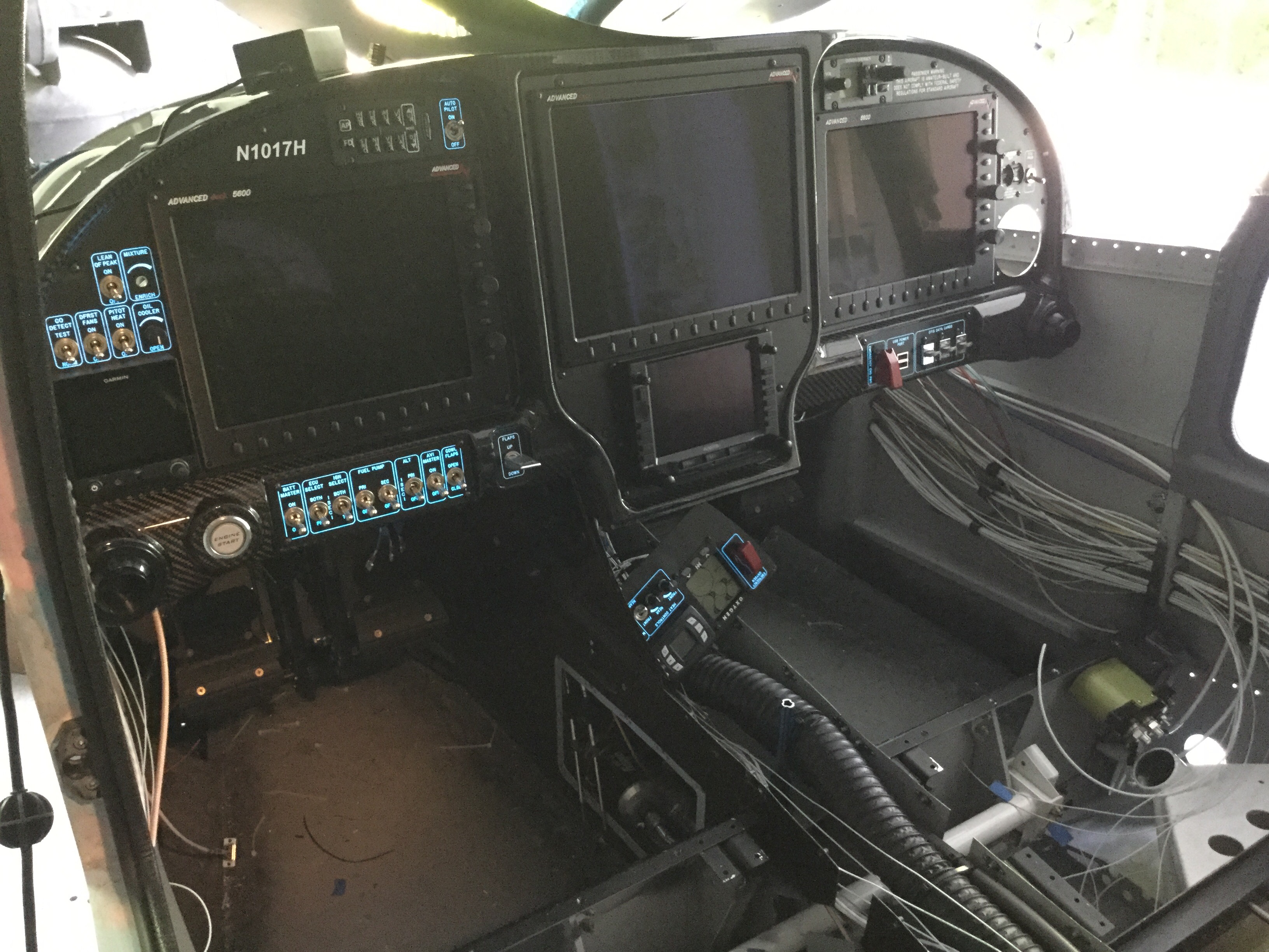
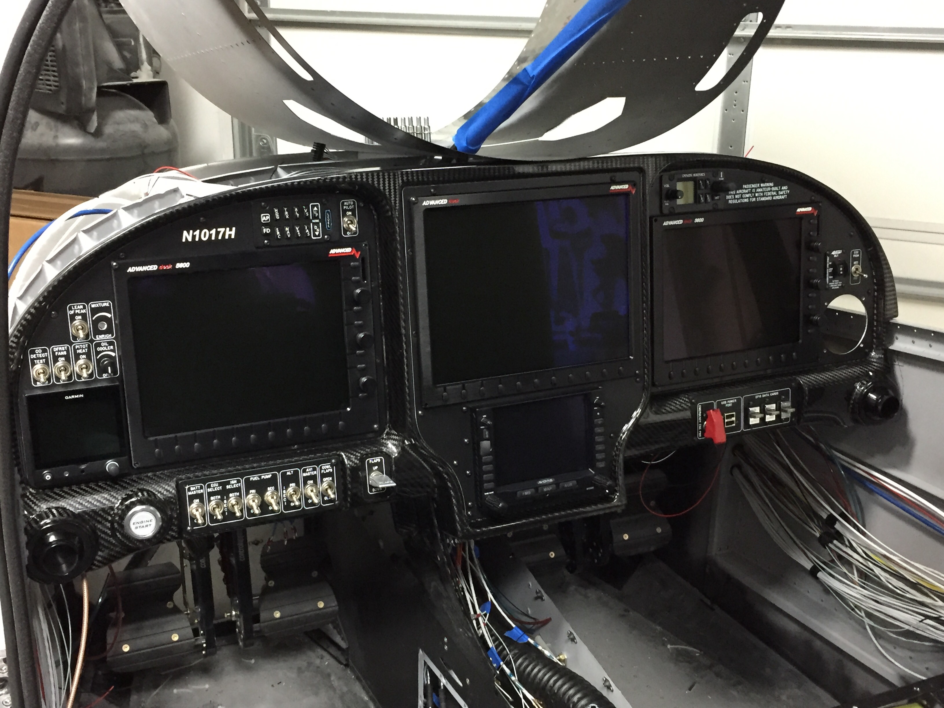
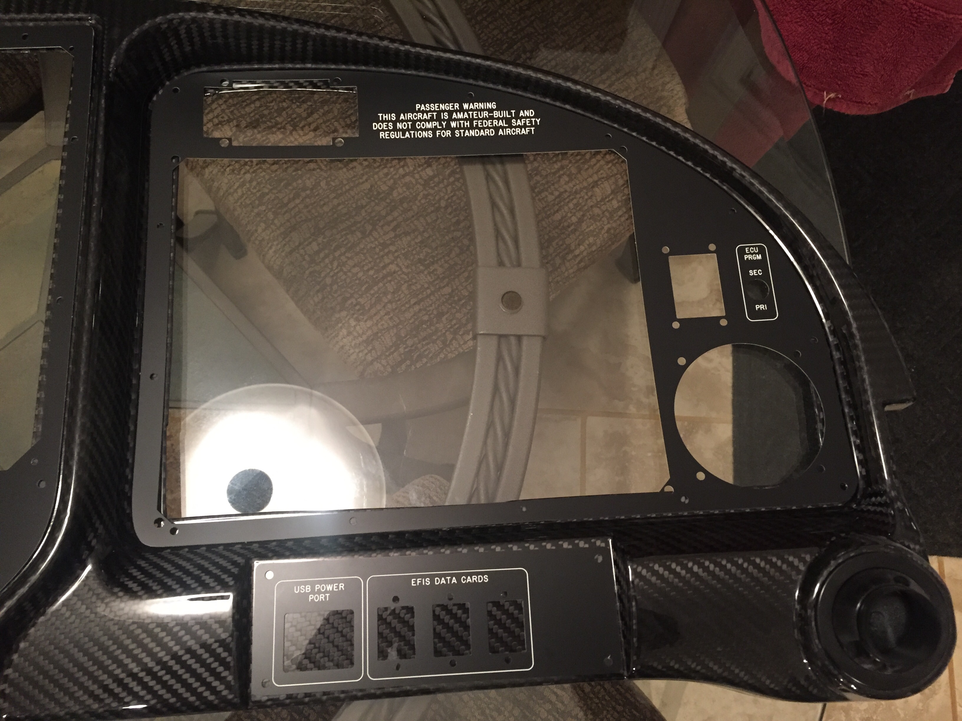
It’s finally time to slide all of the pretty glass screens in place and see what it looks like all fired up.  The cutouts on the panel inserts are exactly the size needed, so clearance was a bit tight.  Pretty soon, I had all three screens in place along with the IFD slid into the tray.  The G5 was installed and I hooked up the last two fittings for the pitot static system and got the tubes plugged in.  The PFD was a tight fit and required several attempts and getting all the wire bundles situated just right on the ACM to allow the connectors from the screen to fit without crimping.

Man, does this panel look awesome!!  I have spent literally years designing the layout and dreaming about this very moment.  I couldn’t be happier with the way it turned out.  I’m really looking forward to sitting behind it and having great adventures with a massively capable avionics suite that is just as suitable for fun VFR flights as it is hard IMC.  The carbon is a great look, the overlays are perfect, everything is in reach, and it is a real show stopper!

I also hooked up the lower console panel back lighting just to see how it works but won’t get the rest of the components connected until after power is applied.  That is the next big step, so stay tuned!

Back that light up

One of my most exciting side projects on the plane is to have a truly unique instrument panel.  From the start, I have wanted a back light system similar to fancier aircraft out there and to pretty much every car out there.  Glareshield lighting, post lights, or dome lights just don’t work or look the same, so I wanted something better.  Ed Krantz did a great job using LED strip lighting but had to do a lot of work to get it working.

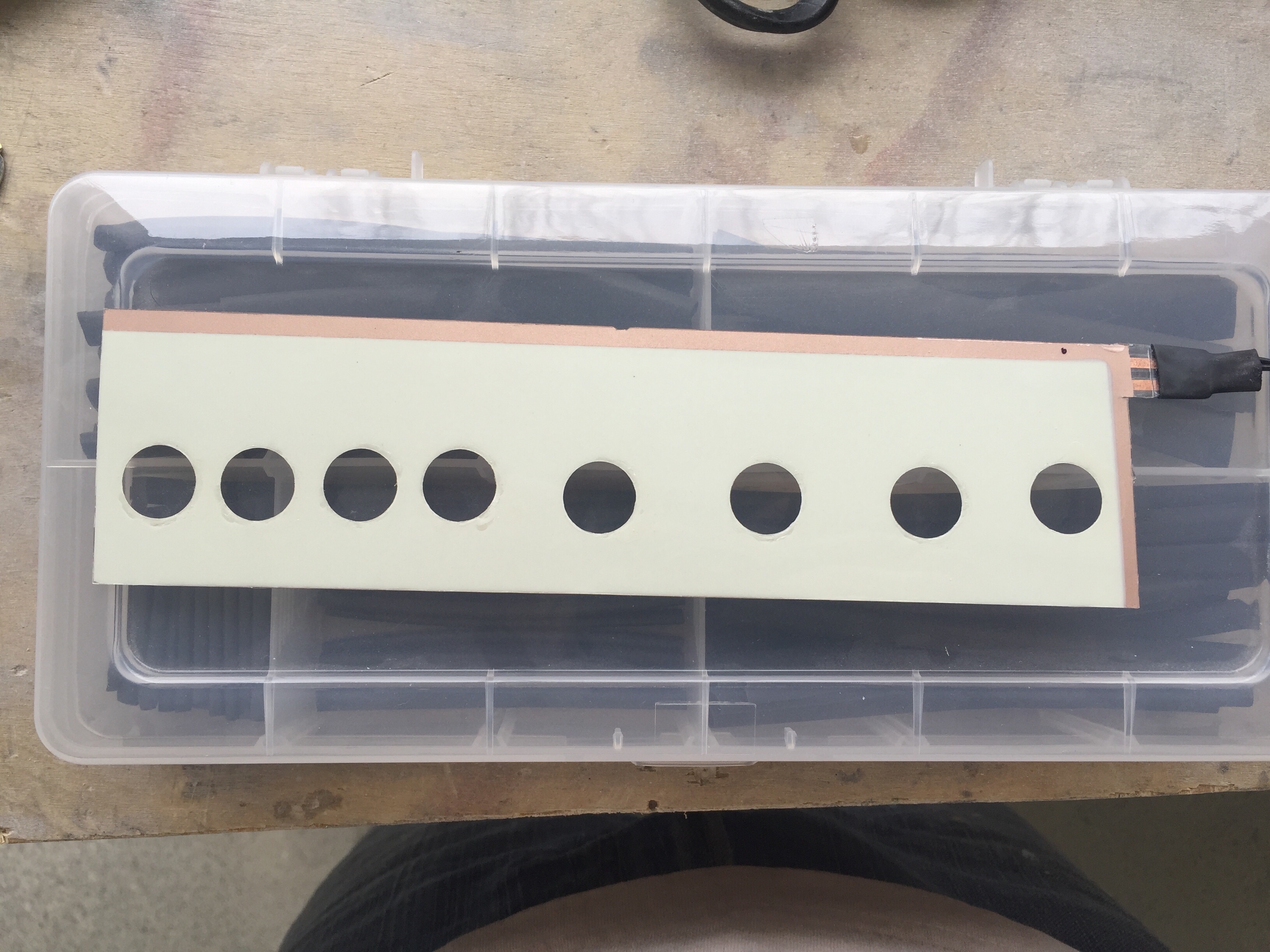
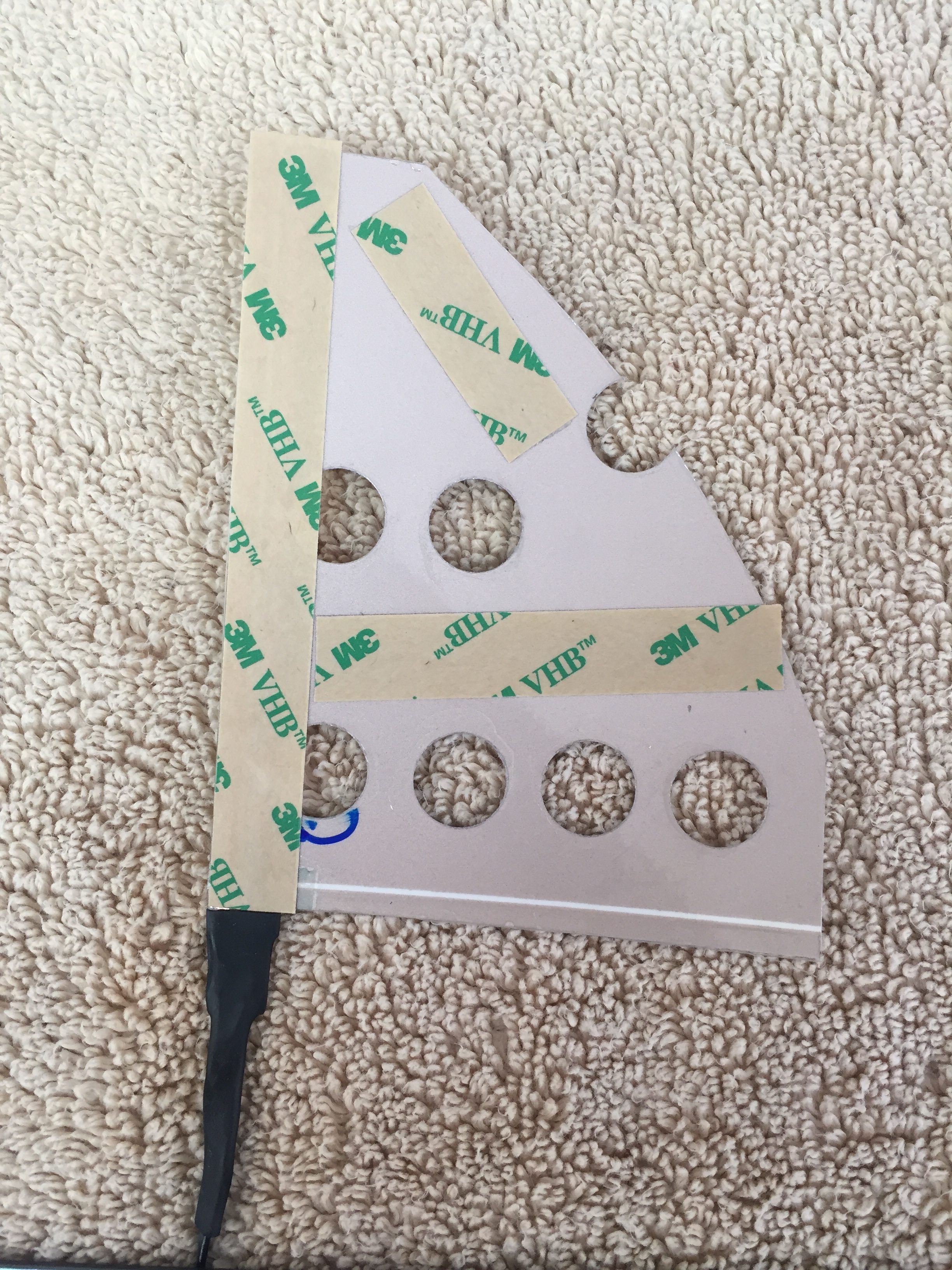
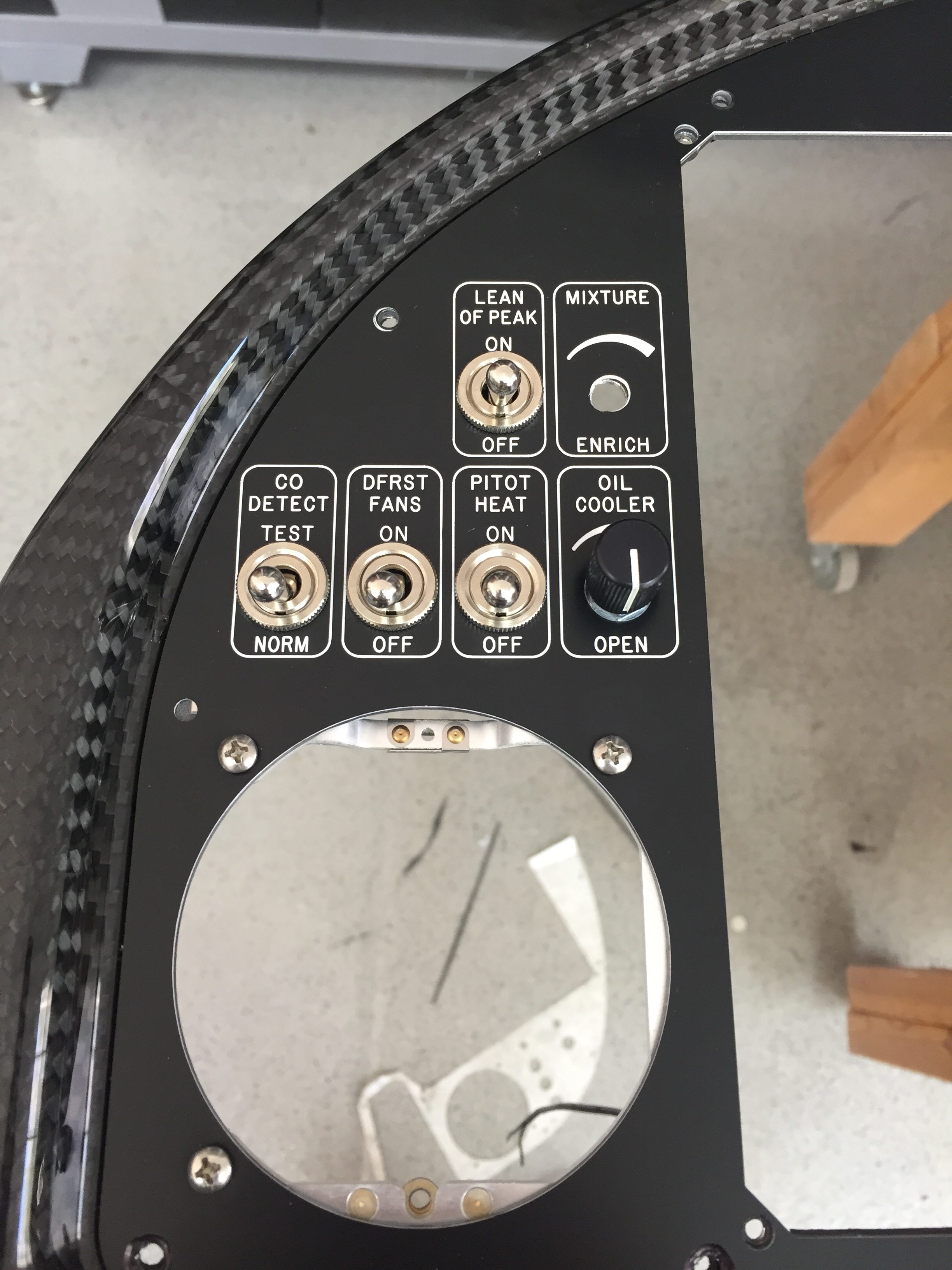
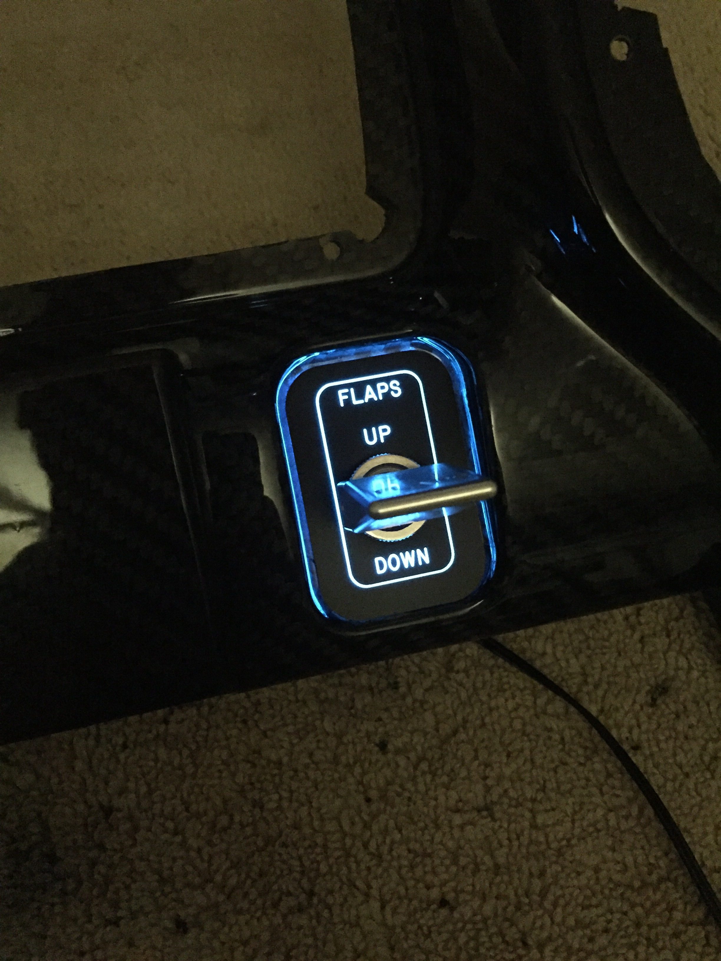
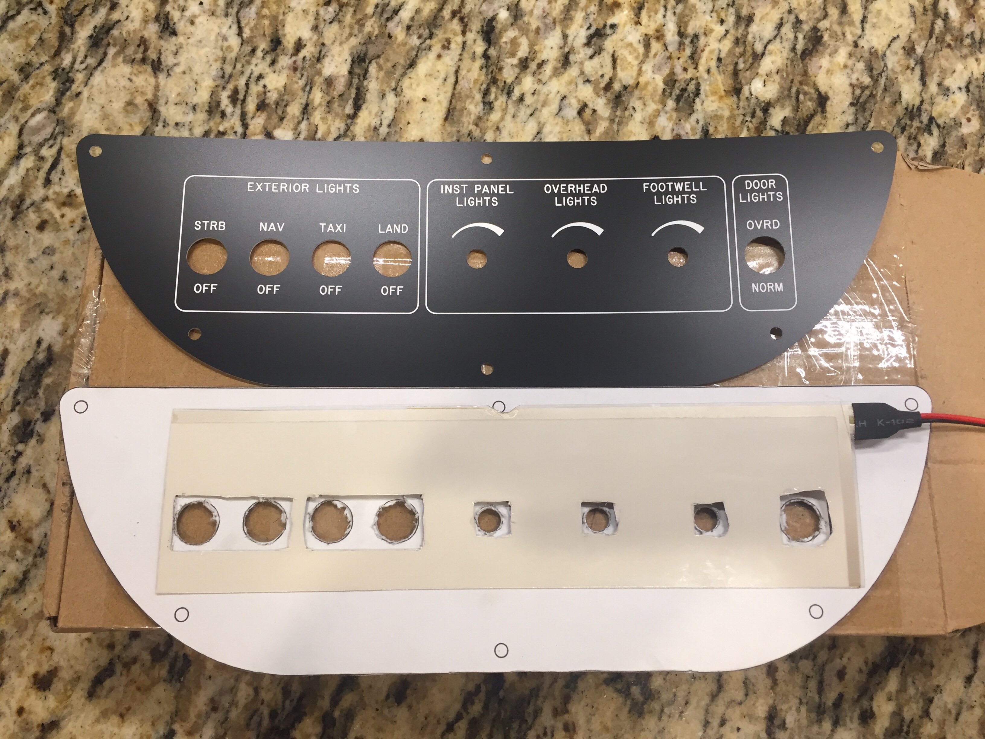
As briefly discussed in THE ART OF DESIGN, I decided to experiment with electroluminecent panels.  These EL panels are almost paper thin, flexible, and can be cut in all sorts of shapes.  Better yet, they are dimmable and have a uniform light output.  After a successful prototype on the overhead console panel, I pulled the trigger and ordered the full layout of the EL panels and the laser engraved acrylic overlays.

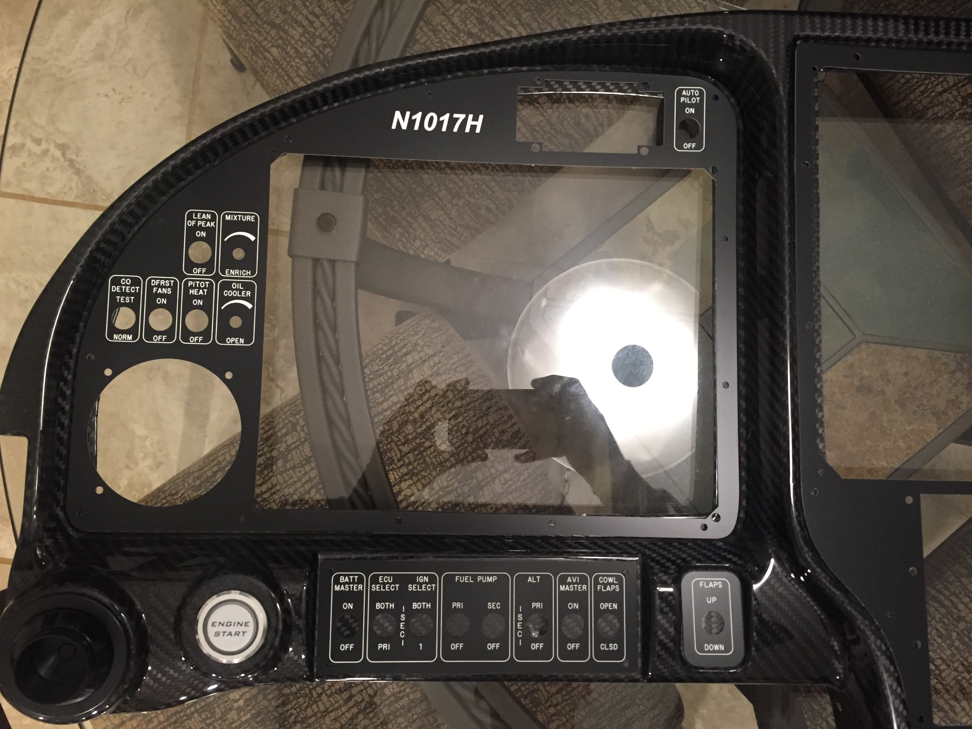
The EL panels came from Marc at Lightkraft via Etsy.  Marc was phenomenal to work with and took a personal interest in the project.  We had to iron out some dirty details on orientation, power leads, size constraints, etc.  I wound up taking his limfacs and finessing the panel layout a bit around the EL panels to make sure everything lit up as desired.  I also had to be strategic on where the power leads would be located along with the two edges that are unlit where the leads run.  On those two sides, it’s about 3/16″ that is unlit and cannot be cut, so positioning those correctly was key.  The other two edges could be cut and shaped in any way needed.  Finally, holes in pretty much any shape can be cut out of the middle to allow for switches or components without affecting the rest of the EL panel.  On any cut edge, the panel must be sealed to prevent oxygen from ruining the EL material.  Marc suggested clear acrylic nail polish which was easy and quick.  The prototype was done in white, but I wanted the final product in all blue.  Marc did a great job taking the 1:1 sized PDF I produced from my CAD design and producing the panels.  He provided a transformer based on the total surface area of the panels so all will be wired together and be on one dimmer.

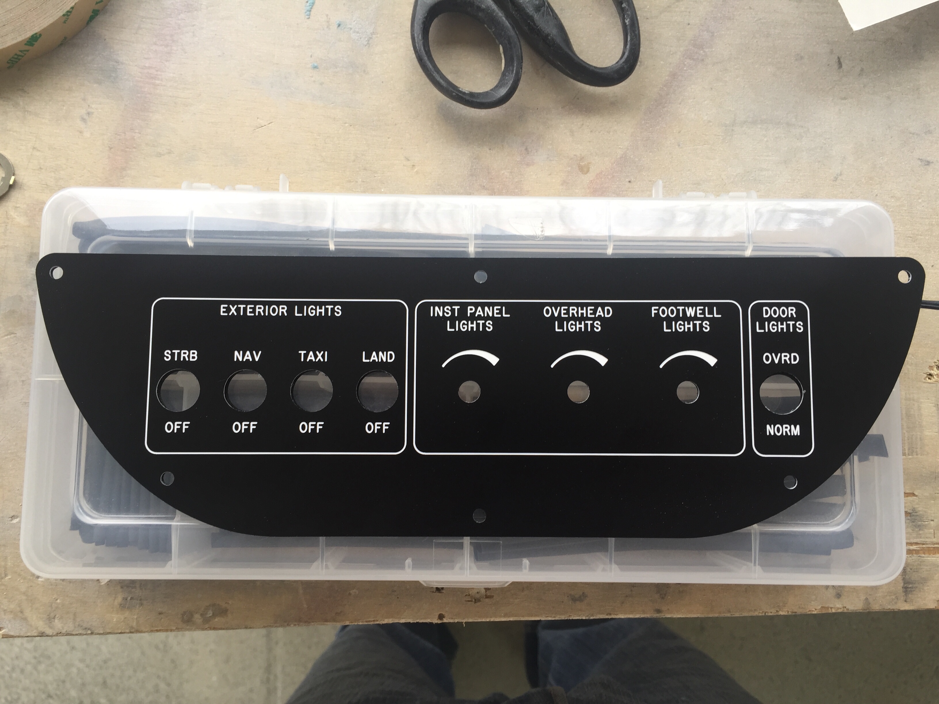
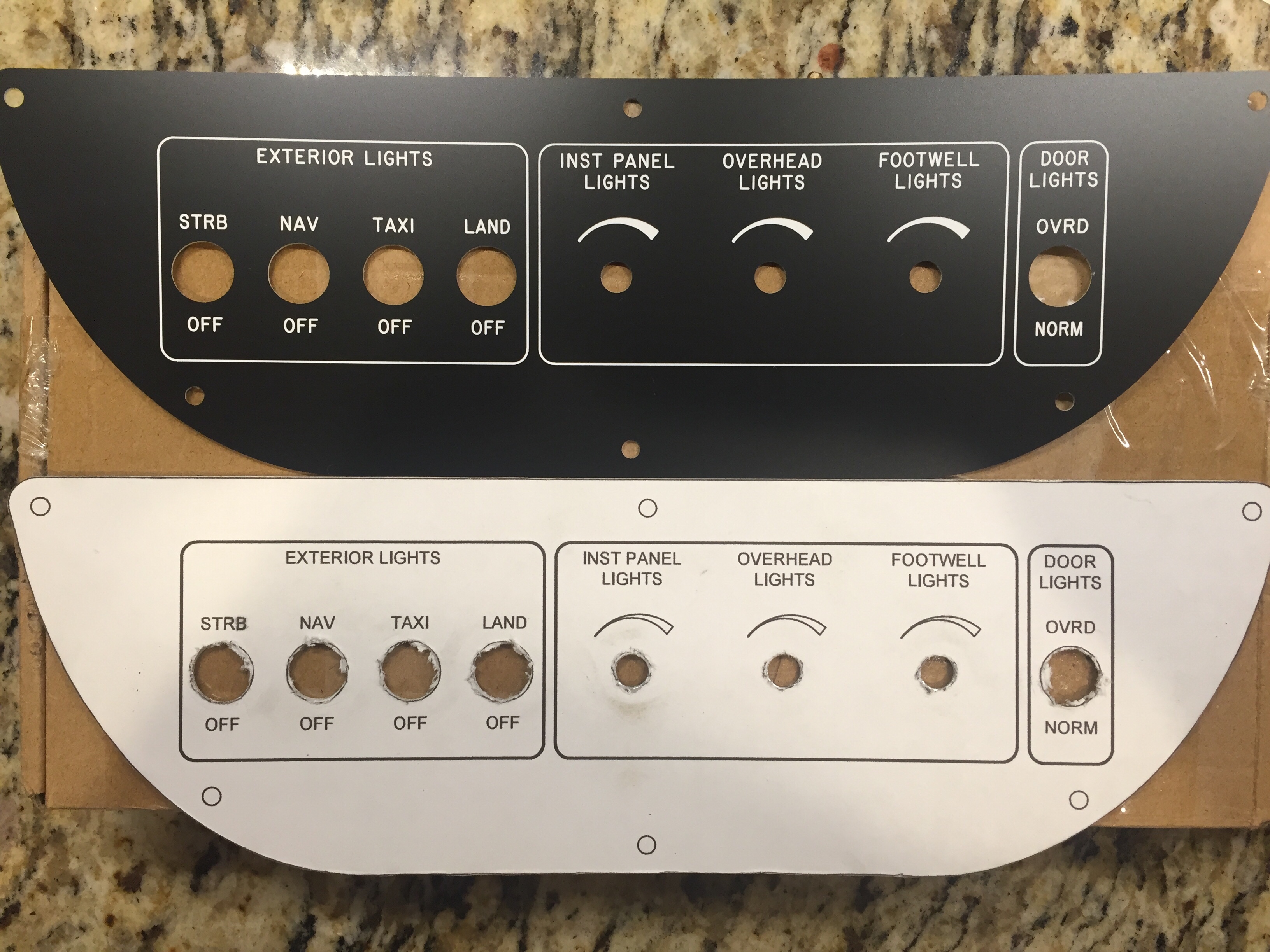
Since AFS helped design and is producing a quick panel for me, the metal inserts for the four major sections of the Aerosport 310 panel are being cut and silk screened by AFS.  I wanted that as a back up to the EL panels just in case those didn’t work out or fail and are not replaceable sometime down the road.  After finalizing the design with Stephan at AFS, I sent the same CAD design to Matthew at Aircraft Engravers and requested all the panels be cut from black on white acrylic, just the same as the overhead console test panel.  Matthew was able to cut all component, switch, and screw holes then laser engrave all of the markings.  The acrylic panels have a self sticking backing so applying them for good is as simple as pulling off the backing and sticking them on the metal panel!

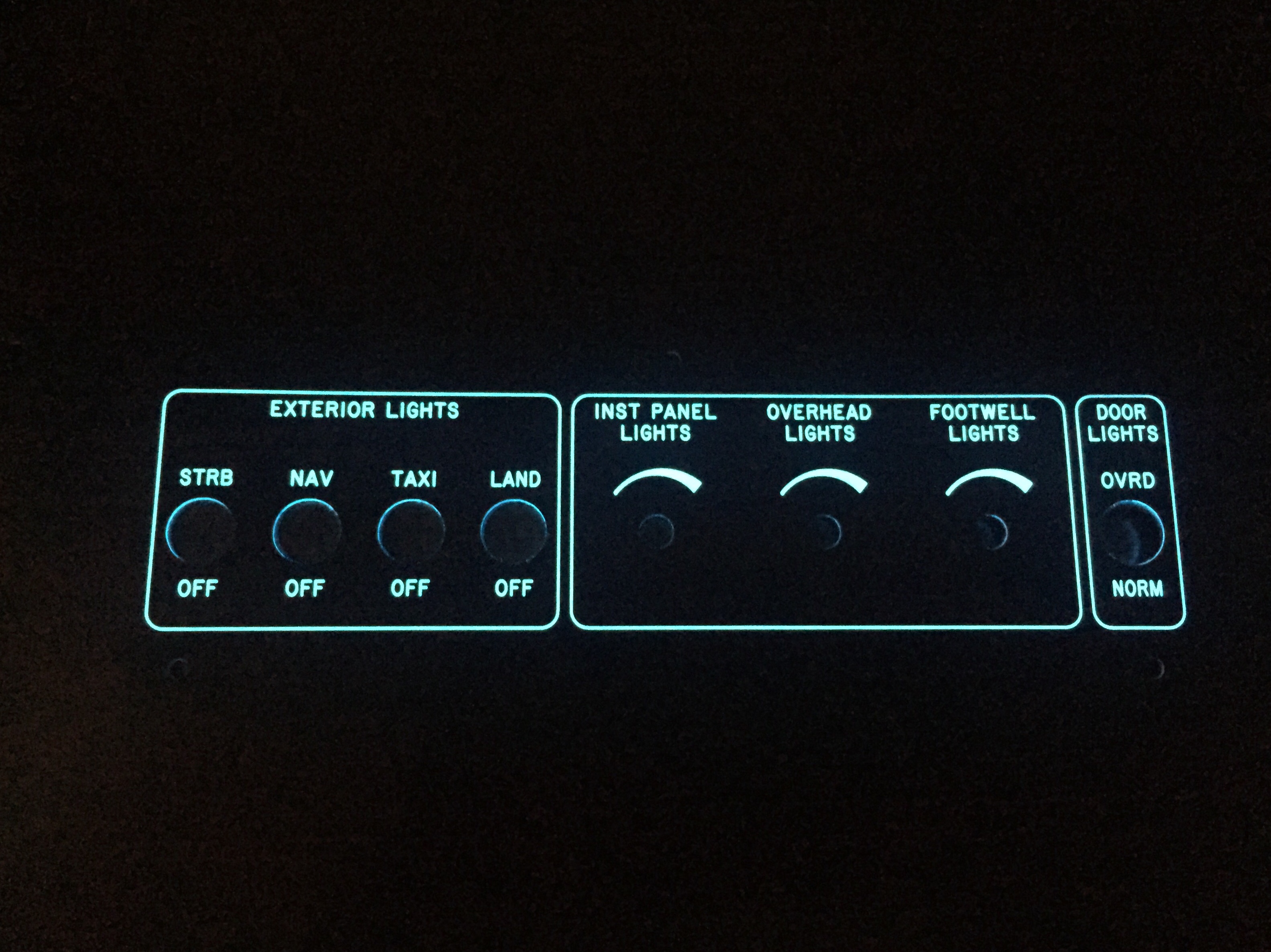
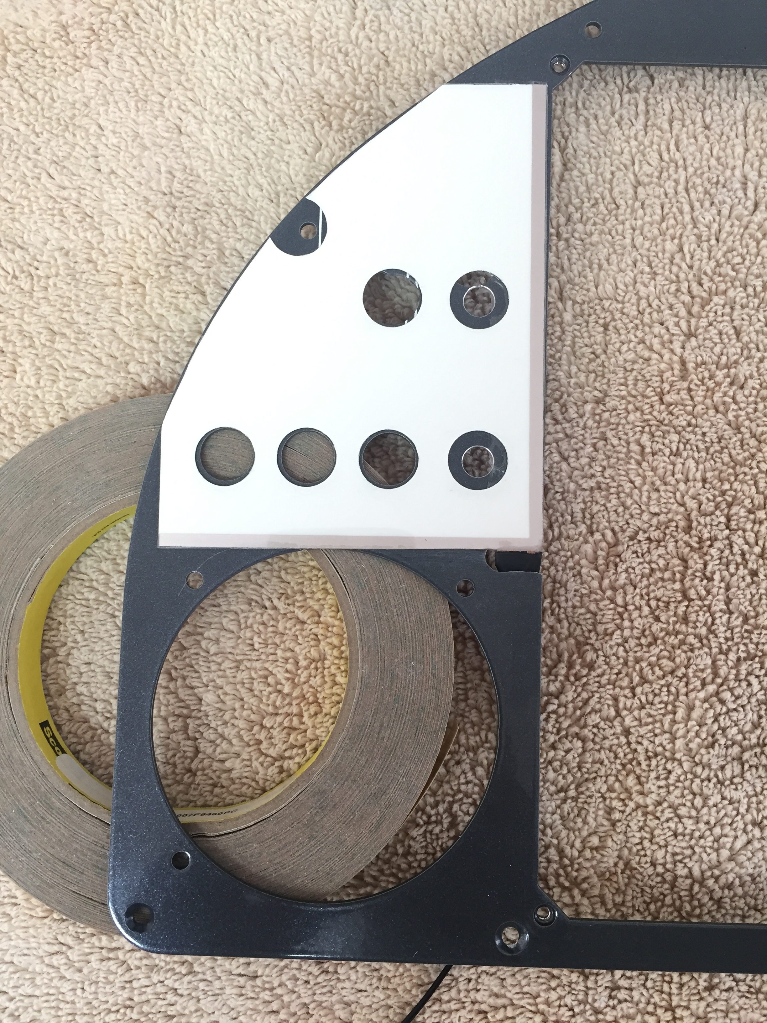
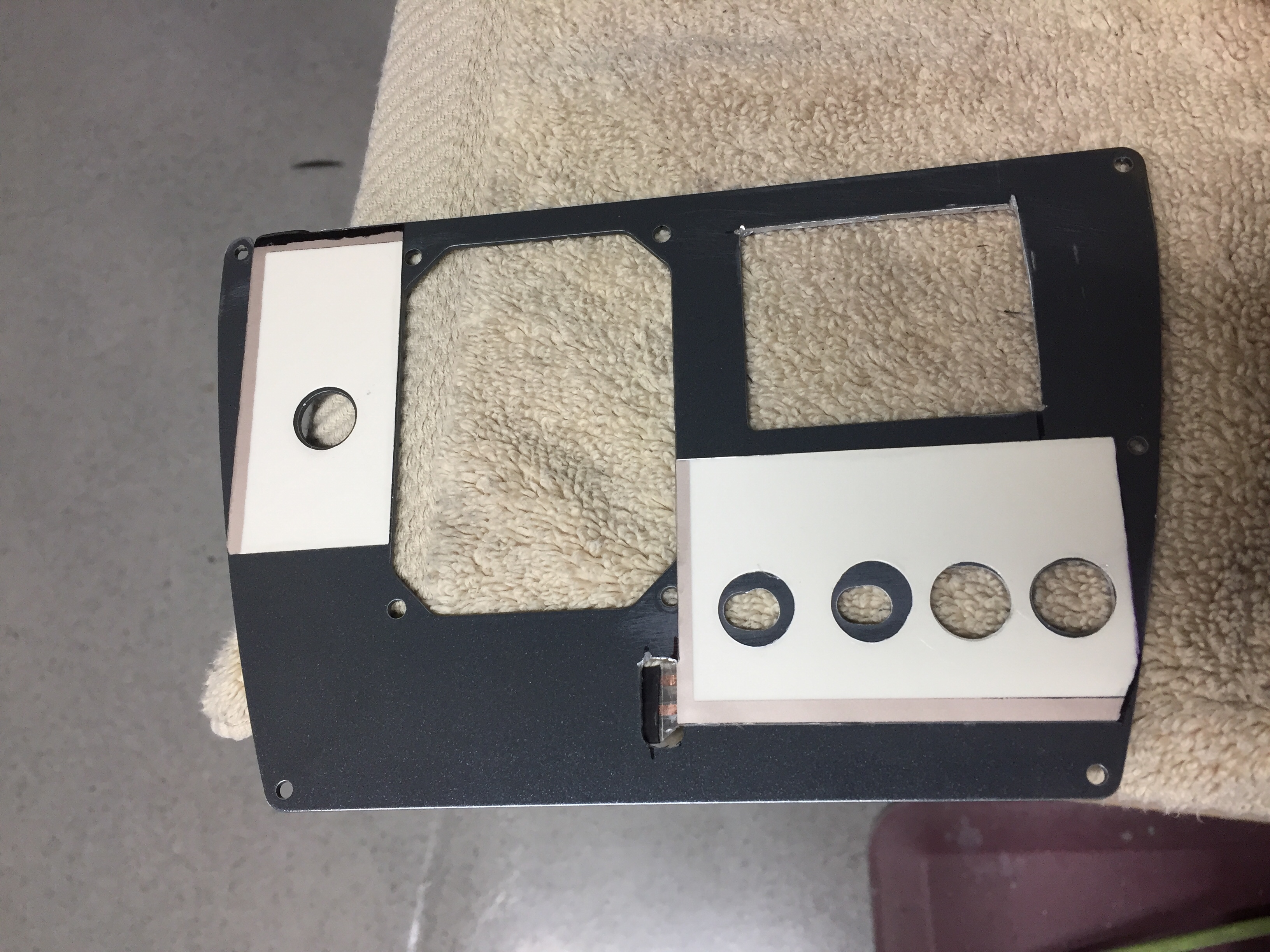
I took some time to ensure each EL panel fit the area needing back light and trimmed a few spots to clean it up.  I used a 5/8″ punch to punch holes for switches and dimmers in the EL panels.  The idea was to avoid the EL panel contacting any metal avoiding shorting and any interference noise the panels may translate to the air frame.  From what I can tell, neither is necessary as metal doesn’t seem to bother the EL panel and test flying the prototype in the Diamond yielded quiet radios and headsets.  After all of the holes were cut and trimming was completed, I turned into a little kid and played with everything in the dark to make sure all engraving was properly lit.

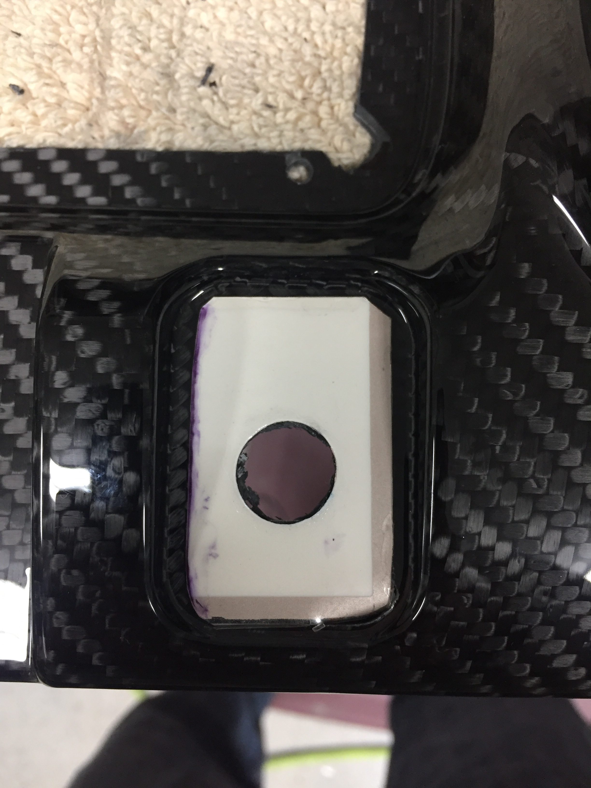
Next task is to cut a relieve for the power leads to rest in.  Since the wire is soldered onto the EL panel, it needs to slip either to the edge or behind the metal panel so that it is all flat once completed.  The areas where EL panels are not near and edge, I cut a slot for the leads to fit through ensuring no exposed lead touches the aluminum.  Several locations will require the leads coming out from the side of the acrylic panel and going into the carbon fiber structure through a slot.  Those are a bit tough to cut out but with patience and a lot of though prior to cutting, it works just fine.  The main switch panel and flap switch panel were the toughest ones.

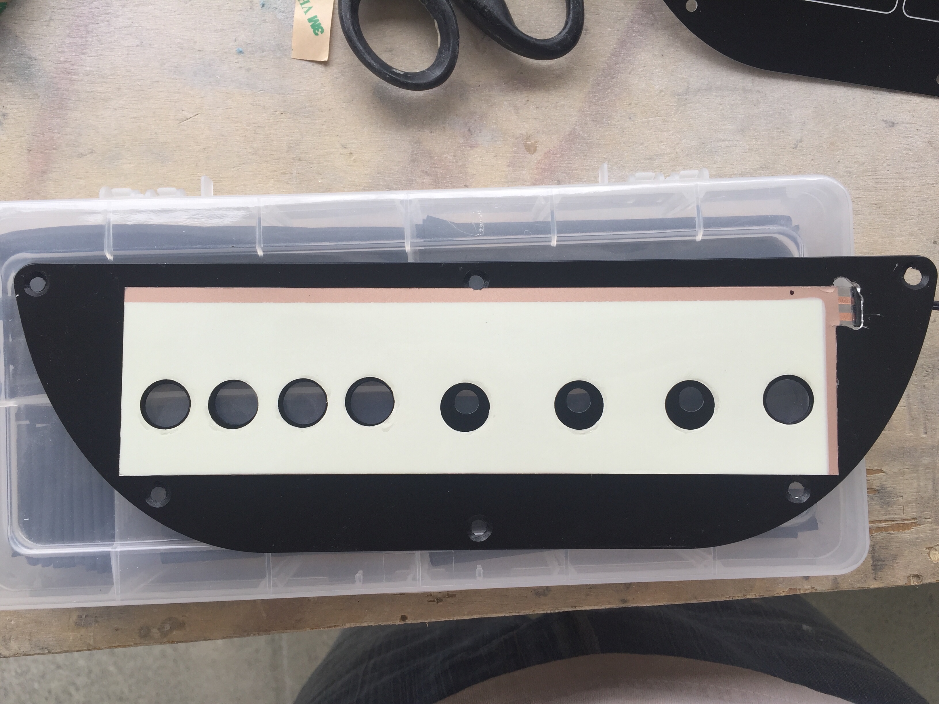
To install it permanently, I cleaned the metal backing panel and positioned the EL panel with 3M clear double sided tape (the same stuff Van’s recommends for trailing edges).  This is really just to hold it while placing the acrylic overlay on top.  The backing is removed from a small section of the acrylic overlay so that I have some adjustment playing the overlay on the metal panel.  Once everything is lined up just right, I removed the rest of the backing and pressed the acrlyic down evenly.

The end result is a sandwich with the acrylic on top, EL panel, then metal panel at the back.  There is just a slight thickness difference over the EL panel, but not enough to be noticeable without really inspecting up close.  If you’re doing that, keep your judgments to yourself!  Switches and dimmers are installed just like you would anything else and before you know it, I was able to screw the panel on the overhead console and fire it up.  I went ahead and wired all of the switches and had the dimmer pots ready to go, so the overhead console and panel is now complete pending black screws coming from AFS!

Overall, I am really impressed with the result and happy I did the project.  It wasn’t cheap, costing about $1000 with most of that coming from the engraved acrylic overlays.  The EL panels were about $200 after all said and done.  The acrylic would have been much cheaper if I had only done the areas around each switch or back light panel, but I wanted a uniform look across the cockpit.  I would absolutely recommend it to anyone wanting a little extra light and wow factor on their build.  The CAD work was fairly simple and fun as was putting it all together.  I can’t wait to get the rest of the avionics and get the whole thing fired up.  She is going to look stunning in the dark!

Shutting the door on the doors!

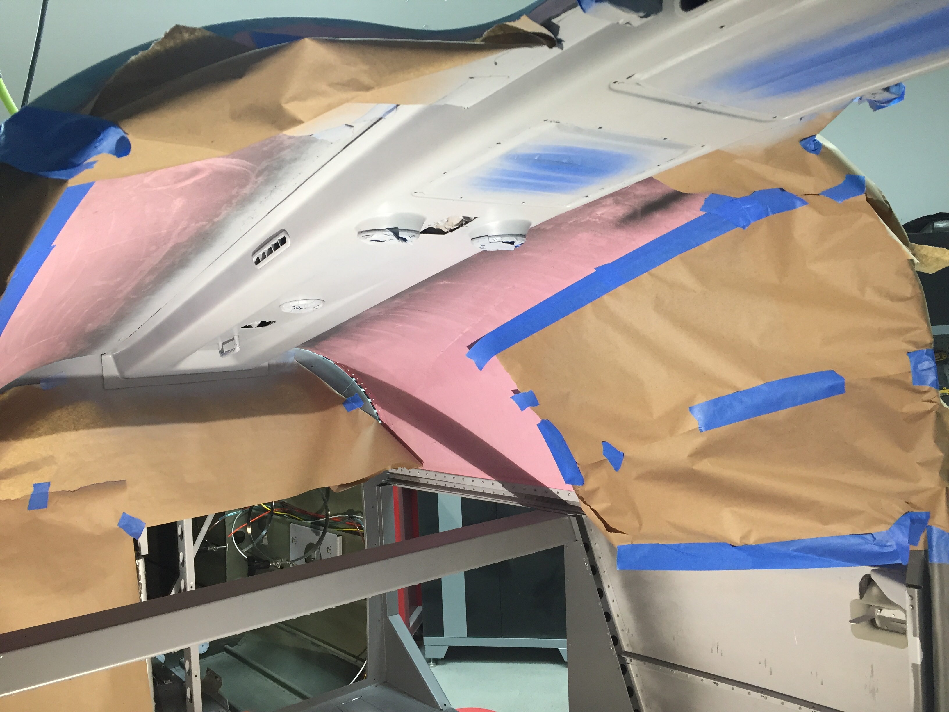
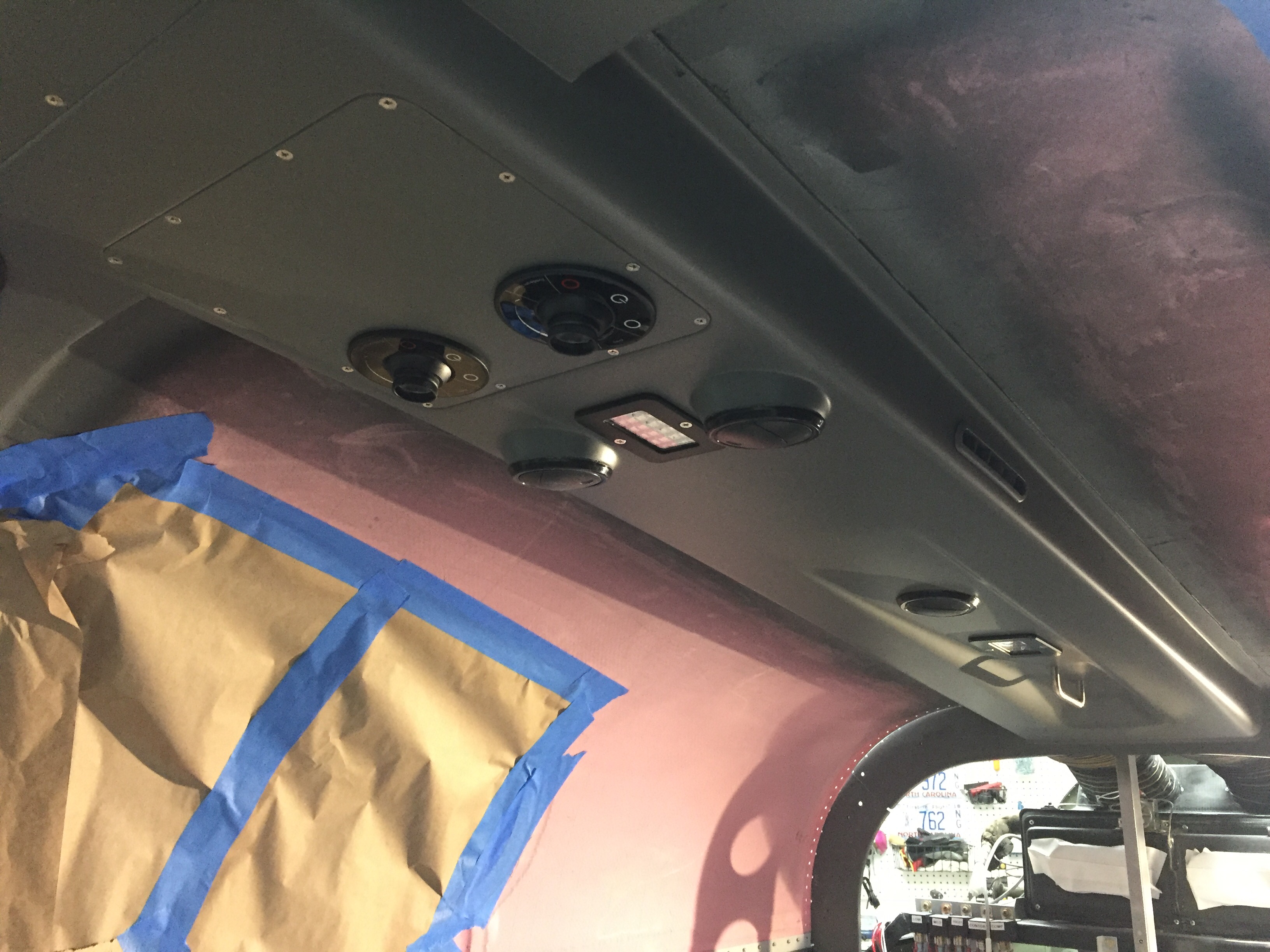
Doing things better the second time seems to be a driving motto for my project.  The paint on the overhead console is a great example.  With it properly prepped, I sprayed primer on it using the adhesion promoter and instantly saw improvement.  Once the primer cured, I did some test scrapes and the stuff stuck like epoxy!  After that, the color was easy, again using adhesion promoter after a good wipe down with tac free.  I followed all of that up with two coats of the satin clear on the entire painted interior.  It’s about time I replace the cartridges on my respirator.

I also fixed the rear foot well spar paint after cleaning the old stuff off and re-scuffing and priming the surface.  I wound up test fitting a few pieces of the carpet just to get an idea of how much metal is exposed and what actually needs to be painted.  The Aerosport carpet is nice, I couldn’t have done a better job myself, but they aren’t an exact fit which is a bit irritating especially for how much it costs.  Not sure if all of the patterns are like that, but the floor carpet for the rear foot well is about 1/2″ too big on length and width, so one side or both will need to curl up a bit.  Never noticeable once it’s flying, just being picky I guess.

The doors are finally done!!!!  The last coat of color and clear went on smoothly and I’m calling them fully baked.  What a royal pain in the ass they were.  I am very happy with how they turned out, though.  I put the Aerosport handle covers on and got the Plane Around center cam final installed with the roll pin.  The door lights went in for good as well. I took my time putting the final door seal on from McMaster Carr and made the seam hidden by the strut and strut bracket.  I used a bit of E6000 glue to ensure no gap in the seal lets water in up there.  Holding my breath, I closed the door and much to my surprise, both closed with the seal on smoothly!  The right side door is a bit more firm on the handle motion, but the wife is happy with it which is all that matters.

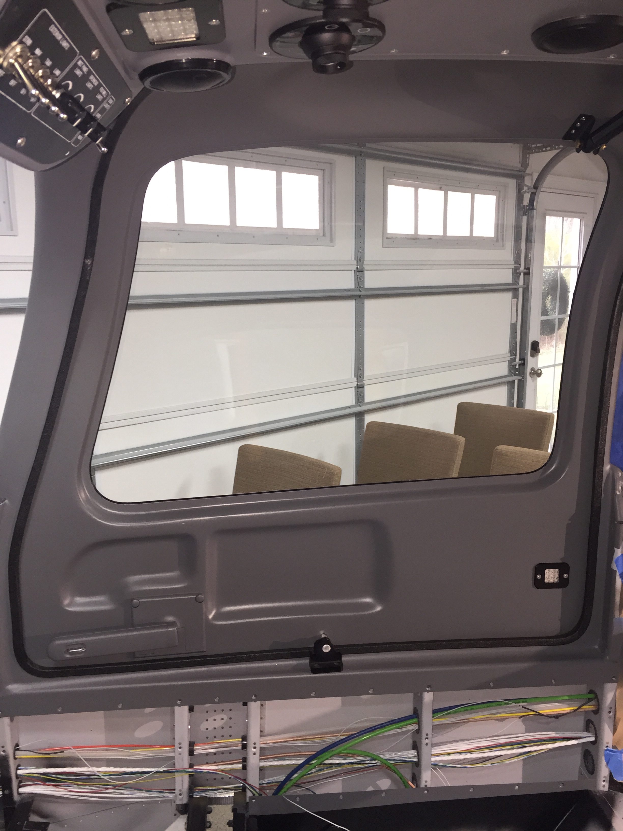
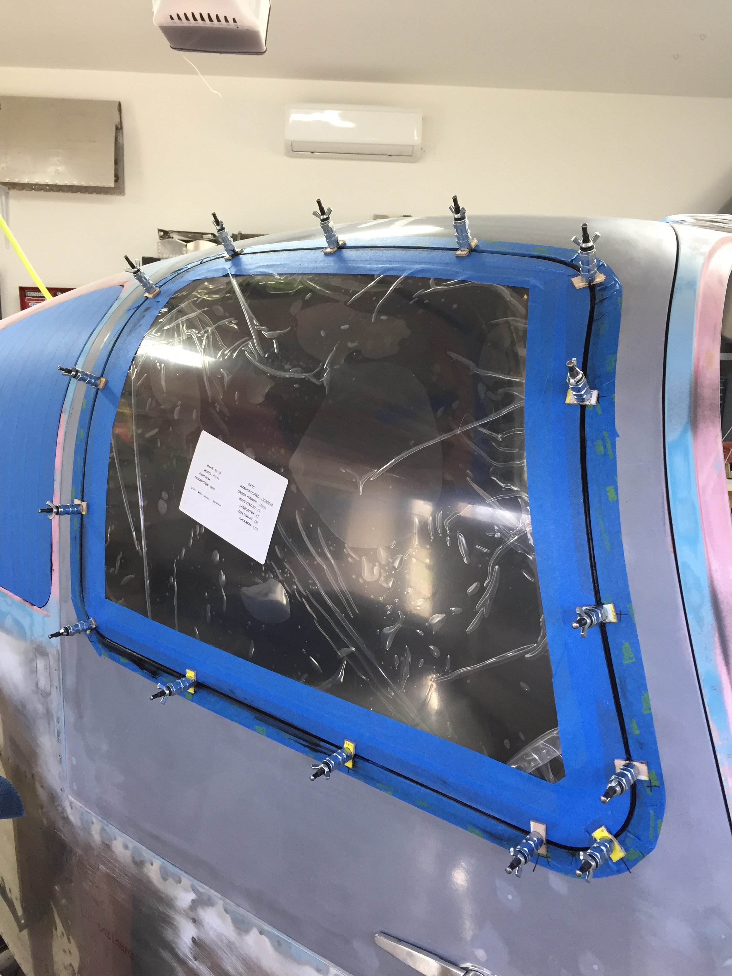
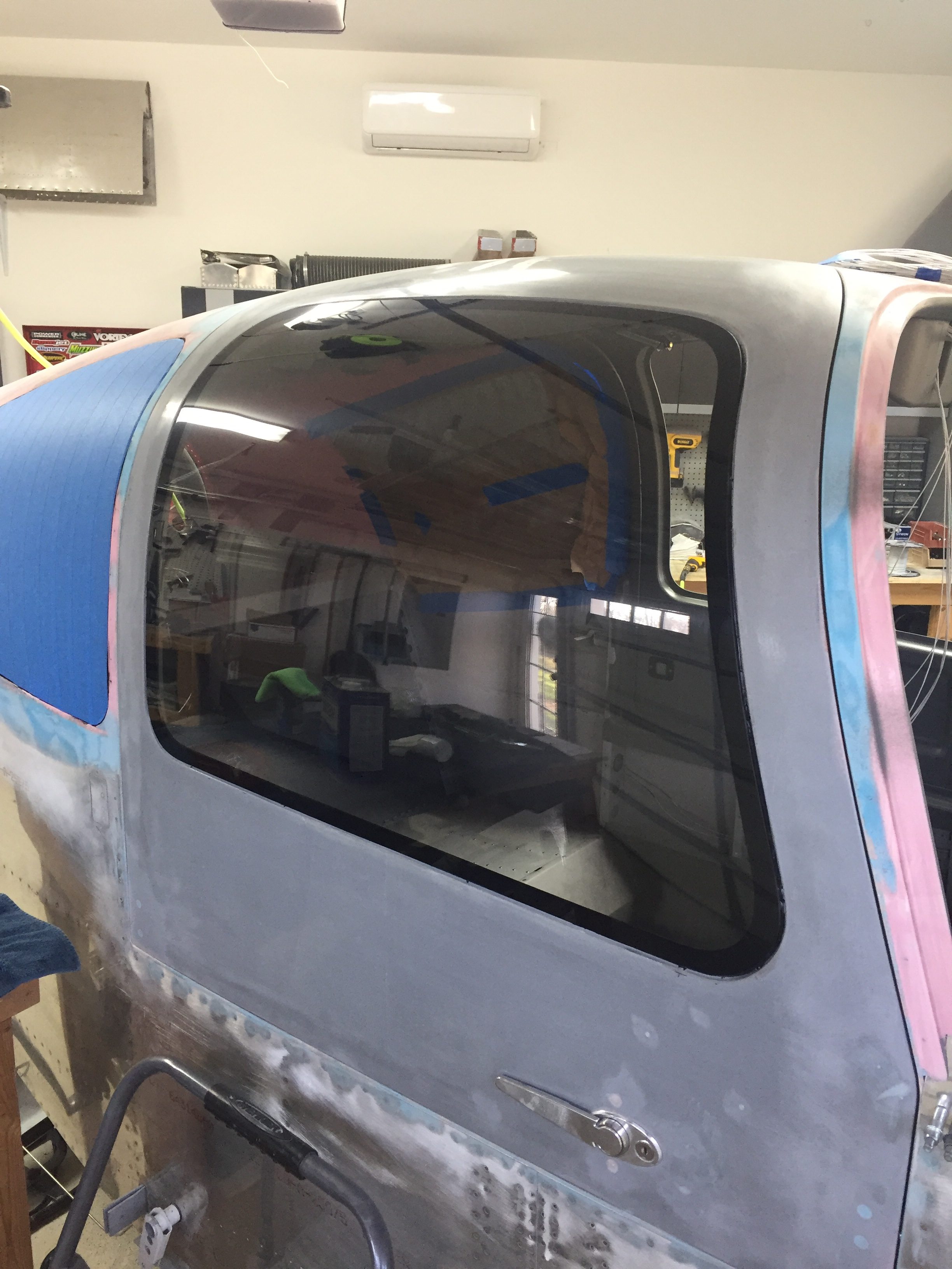
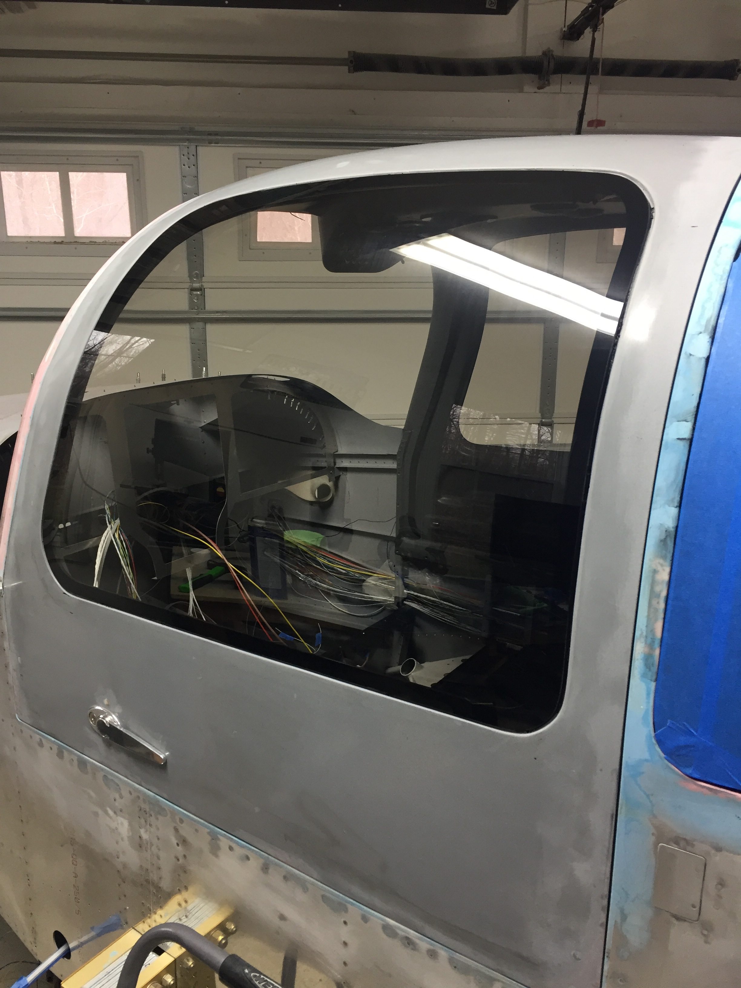
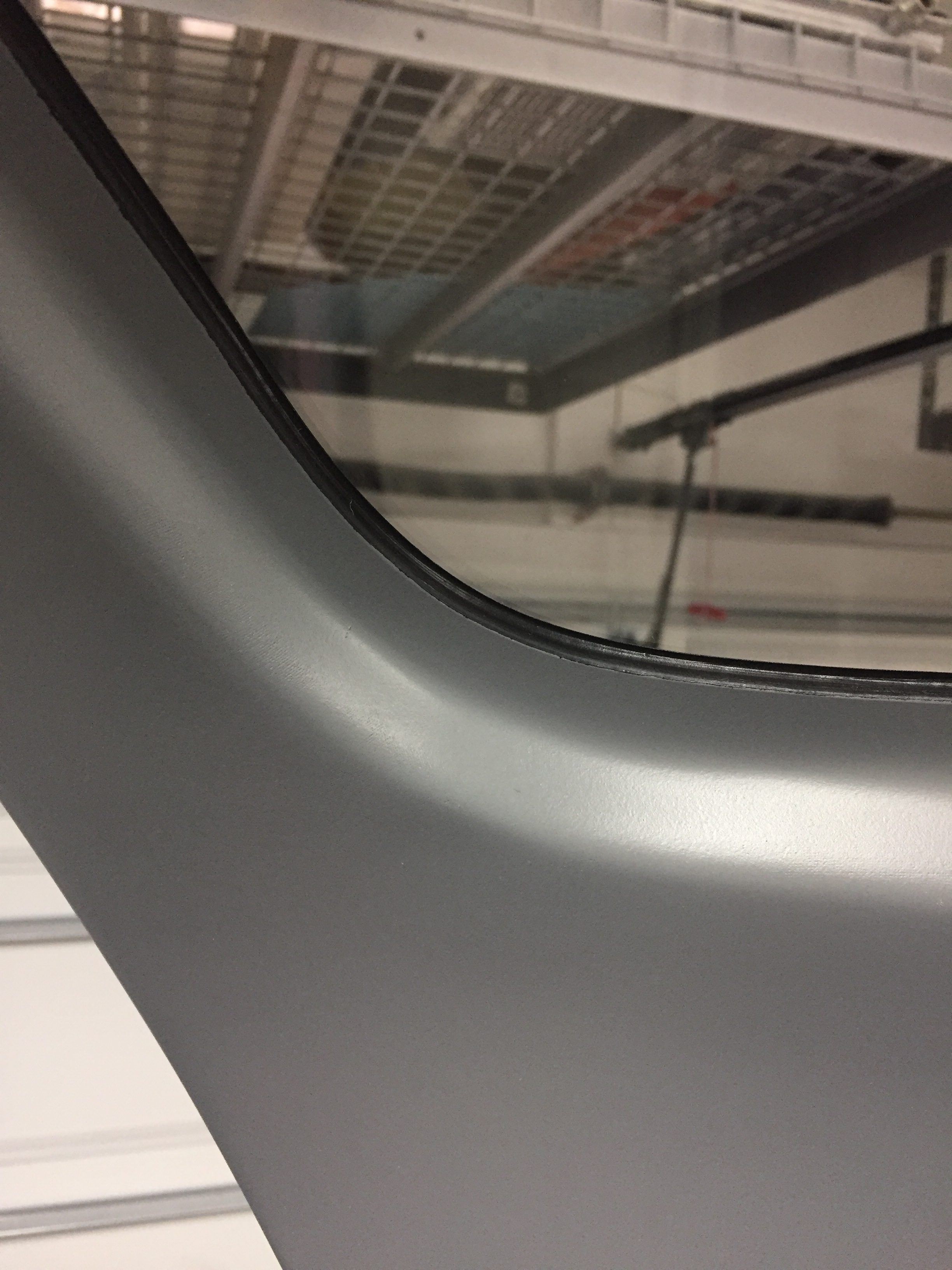
Now that the paint is all complete on the inside, I was ready to install the front windows.  Repeating the process from the rears, the right window went in very smoothly and thanks to good prep work and patience, the inside finish is nearly perfect.  I wound up with a very nice fillet of adhesive creating a nice finish around the perimeter of the door cutout transitioning to the window.  I did notice that the strut now feels much better with the extra weight and doesn’t cause the door to fly open violently.  If anything, it needs a bit of encouragement to go all the way up but has no problem keeping the door open once it’s there.

It took one more evening of work to get the left window in which again went very smoothly.  One additional piece of prep was to put masking tape on the outside of both front windows to help clean excess adhesive from the gap.  It will just make paint prep a bit easier and quicker.  Again, that gap gets filled in with more adhesive after paint for a flush clean look and finish.

I’m back to cleaning up the inside, yet again, of dust and debris since the windows are now in and I can control what goes into the cabin.  The seat belts and receptacles were bolted back in and I riveted on the baggage door panel and gas strut (which I keep forgetting is on when the damn door hits me in the stomach).  Avionics are shipping soon so I need to get the wing root wiring harness complete to be ready to put the expensive boxes in next.

Bringing up the rear

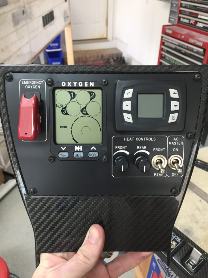
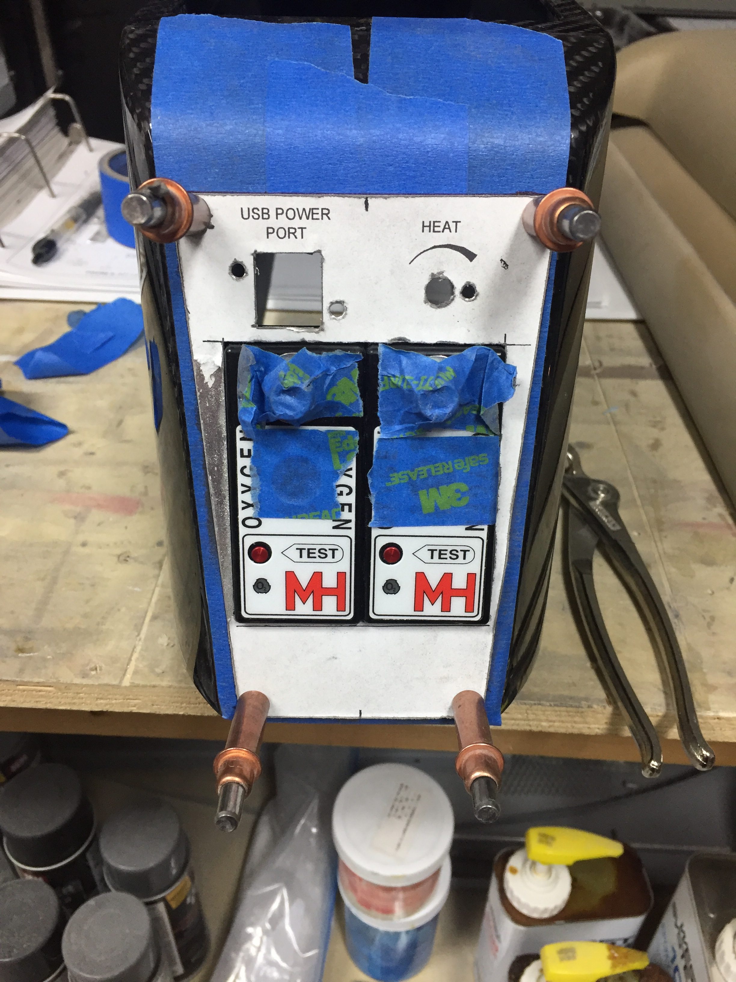
Now that the carbon fiber bits are cleared, I went to work on the rear panel for the back seaters.  My original plan was to mount the oxygen ports, a USB power port, heat control rheostat, and headset jacks into the rear console but it all just wouldn’t fit.  The O2 ports had to stay there, as I didn’t want them in the side panels due to lack of room, so the headset jacks got the boot.  I drew up a layout based on the measurements of the rear panel area.  The carbon is too thick and rigid for the ports to cleanly snap into so I will use AL with a matching acrylic overlay just like the instrument panel up front.  I was able to keep the power port and heat control on top.  I won’t be back lighting these as there isn’t much room and I figure at night a task light can be turned on easily.

I did need to come up with a way to secure the O2 ports, so I used a scrap piece of carbon and installed a few nutplates before epoxying it into the console.  I had to trim the brackets of the O2 ports so they fit side by side as well.  In the end, it’s a nice fit and still allows easy removal for maintenance.

I used some advice from TCW Tech folks to add a source selection switch into the controller for the rear heat servo.  I had to cut the rheostat off of the circuit board and ordered two matching ones from DigiKey, wiring them up with the control wire going to the switch.  This will allow me to control the rear heat using the rheostat mounted up front or give control to the rear seaters.  Testing with the multi-meter confirmed the desired function so those were tucked away for future install.

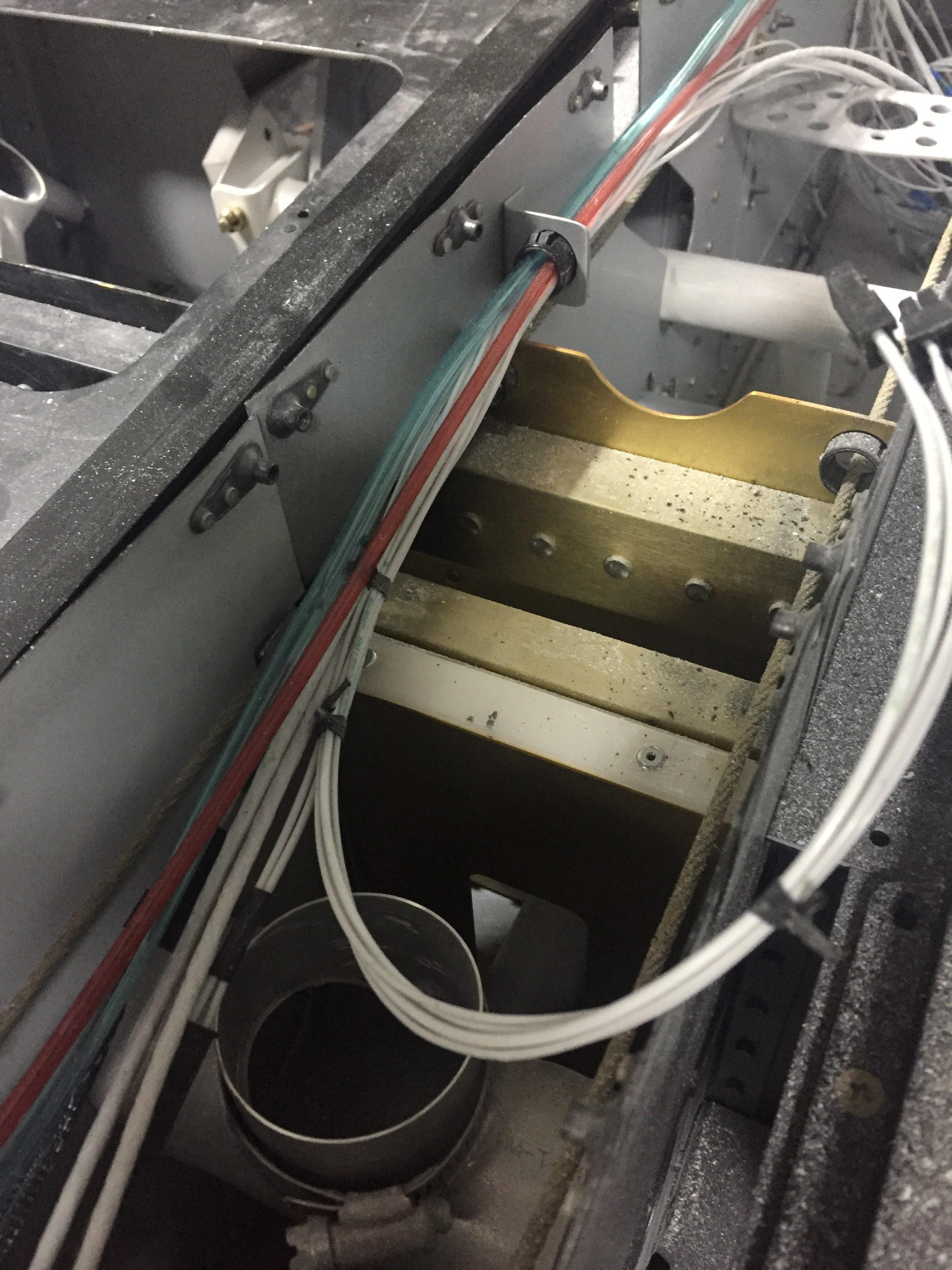
Now that I knew where the rear O2 ports would exactly be, I could continue the plumbing of O2 lines.  That also led to running the wires to the O2 ports, power port, and rear heat rheostat.  I fabbed up a few bushing holders to attach to the tunnel and ran everything down the left side.  The front seat headset jack holes were drilled inside the armrest cubby and the wires will be secured onto the tunnel cover.  I placed connectors on all of the wires so that the tunnel cover and center console could be removed for maintenance without needing to remain attached via wires.

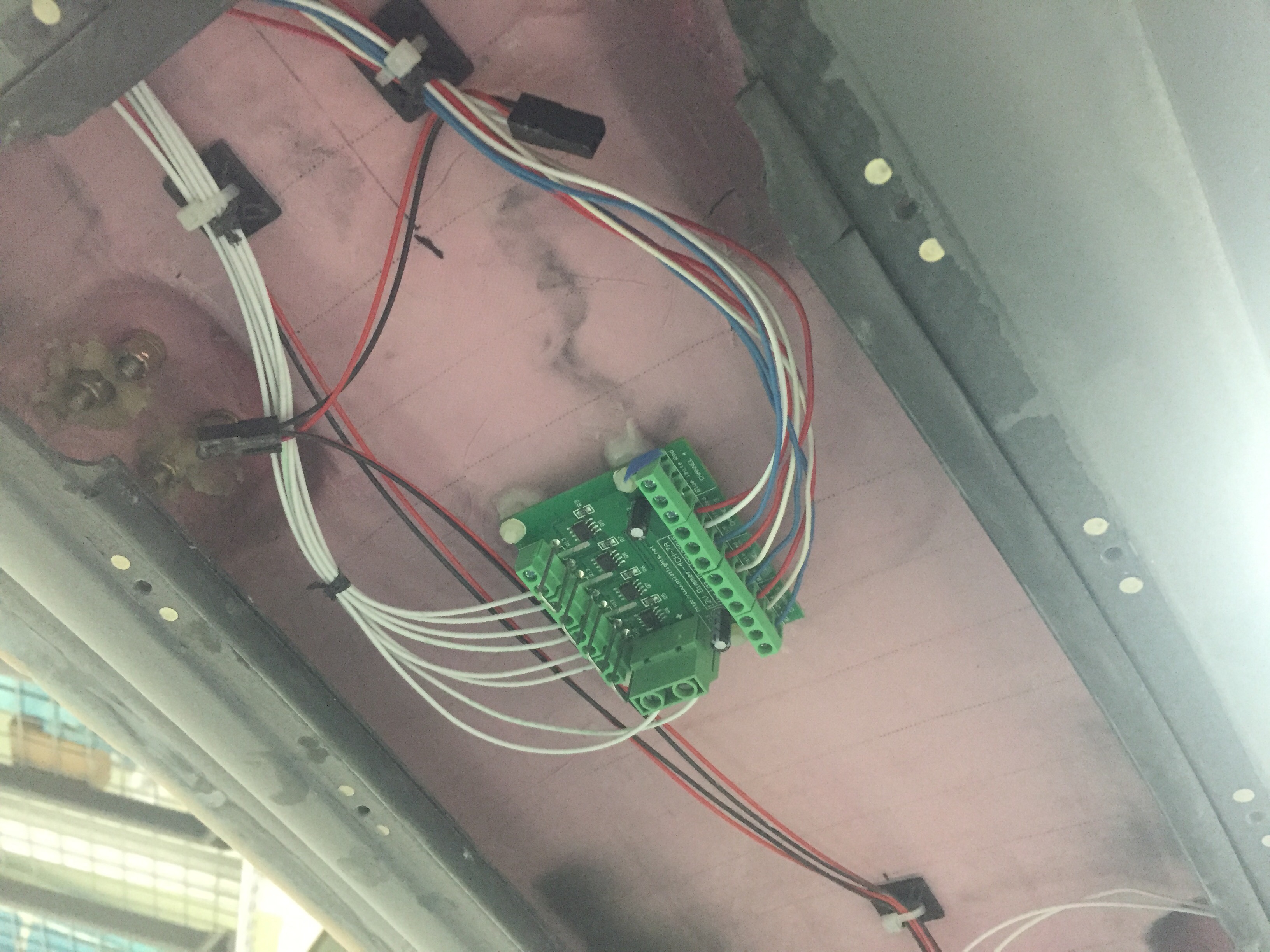
I also ordered a four channel dimmer from Pilot Lights to replace the three single channel dimmers for the overhead panel.  They all would fit up there, as space is tight, so this was  a good solution.  I’ll have a spare channel if I want to add anything later.  I chose to epoxy the mounts to the overhead cabin top which kept some of the wiring runs short.  All wiring for the overhead will be coming up through the center post from the sub panel.  I went ahead and fabbed up the wires for the switches and controls on the overhead so I could ensure it would all fit within the post – no issues there.  With that bit done, I was able to close up the overhead console minus the switch panel which is waiting on the back light panel.

Oh yeah, I sanded more on the doors.  You know, the same thing I’ve been doing for months now.  Gah, the damn things are never going to be done.

The art of design

If you aren’t building, you probably don’t care about this article regarding how and why I laid out my instrument panel the way I did.  For those of you that are building, be my guest and read on.

I have spent many Air Ventures looking and playing with avionics and decided some time ago that AFS was my favorite.  I don’t have anything against others, but the layout, functionality, and features of the AFS just fit perfectly for me and my flying mission.  I’m going to fly a lot of IFR with my airplane, as I already do with the Diamond so want a very capable suite of avionics up front.  I also don’t want to upgrade or add on for a very long time so I budgeted to do everything I wanted upfront.

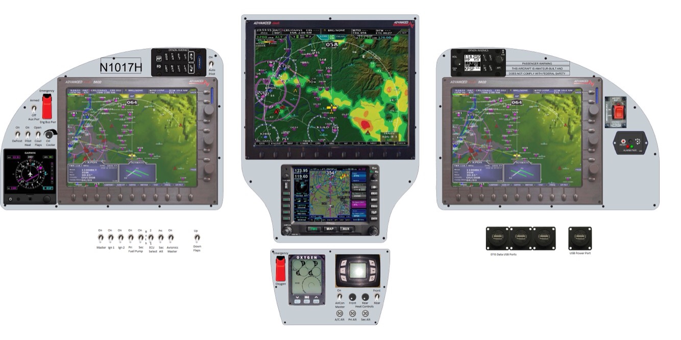
A quick run down of the panel includes:

Two 10″ PFD touch screens

One 12″ MFD touch screen

Dual ADAHRS

IFD 540

Garmin G5 as backup instrument

XM radio and WX

ADSB in and out

Oxygen control head for MH 4iP

A/C control head

Space for SDS control head

Toggle switches and rheostats all matching

All controls that I need located to the left of the center console – no reaching over my pax!  Now, my wife is not a pilot and doesn’t really need the PFD in front of her, but we both like her to be situationally aware and I fly with other buddies that will appreciate a PFD on their side.  It also allows me to one day teach someone else to fly easier.  Again, I don’t want to have to put the airplane down for an upgrade later.  Do it right the first time.

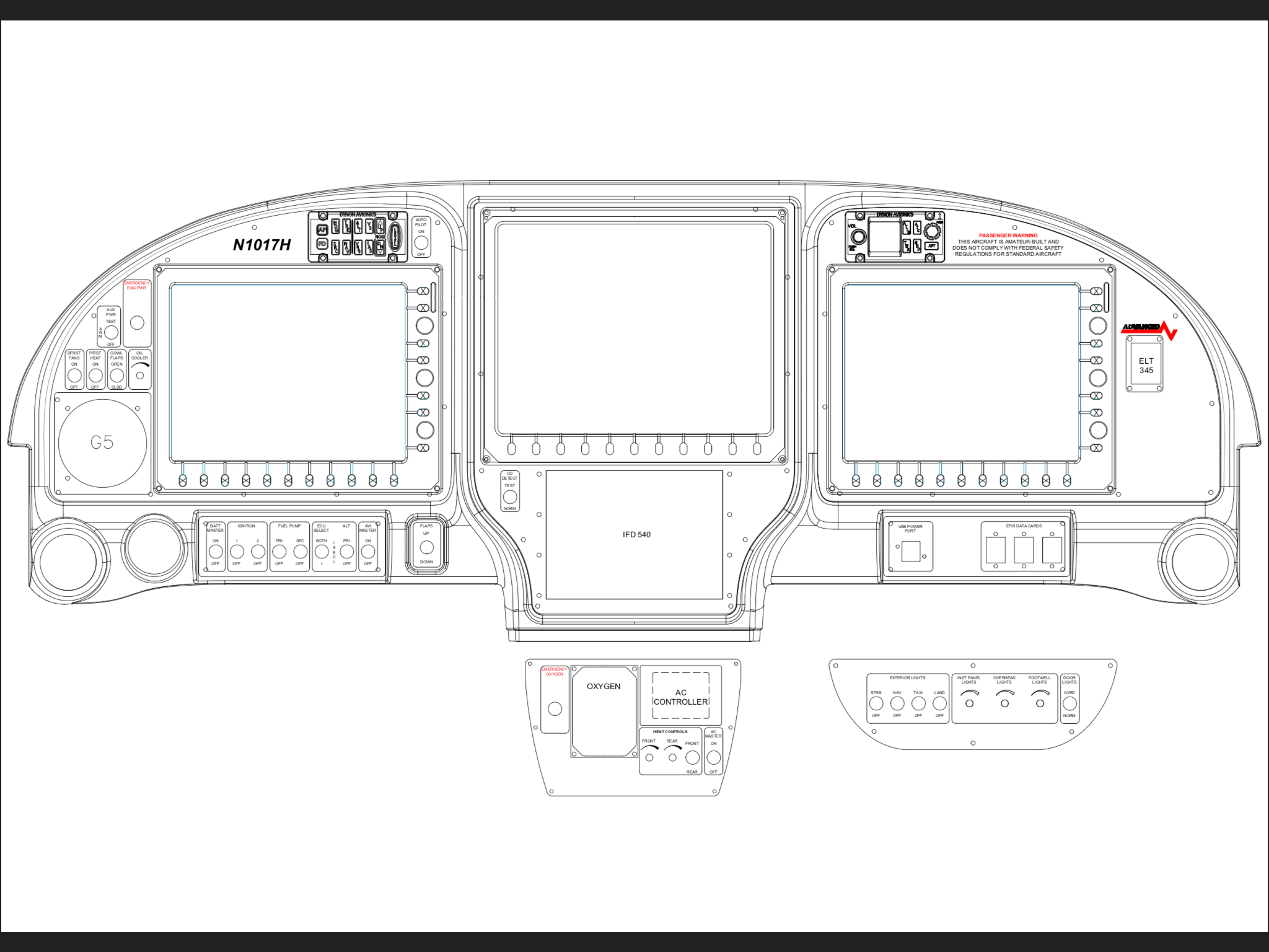
The big pieces go in rather quickly as there aren’t many options of where to put them.  My main concerns were what switches go where and how to get a good flow on the order of switch groupings.  I also was determined to create a back light setup for the switches much like Ed Krantz did on his plane.  More on this later.

With the main components located, I decided on all lighting switches and dimmers to be located on the overhead console.  The upper left has the “misfit” switches like defrost, pitot heat, oil cooler, etc.  The main switch panel in front of me will have master switches and all engine controls in order of startup procedures.  Finally, the lower console will have the O2 and cabin climate controls where either left or right seat occupant can easily control them.

The space for the SDS control head is not ideal, but that instrument, should I go with SDS, is really only used during testing and tuning.  The EFIS will display all engine parameters for normal operations and I haven’t even decided if I’ll mount the display on the panel or remote mount it for use only when I need it.

I do a lot of night flying and despise red dome lights or using a flashlight.  While all three screens and the GPS will put out a good amount of ambient glow, I wanted the switches to be properly backlit to add that extra pop to the panel.  While playing around on the internet looking for lighting solutions, I came across electroluminecsent or EL panels.  They are a really neat product, only about 1/32″ thick and available in many different sizes which are then trimmable with a few restrictions.  All run off of a 12V transformer and provide equal, dimmable, light across the entire surface.  Perfect for what I was wanting!

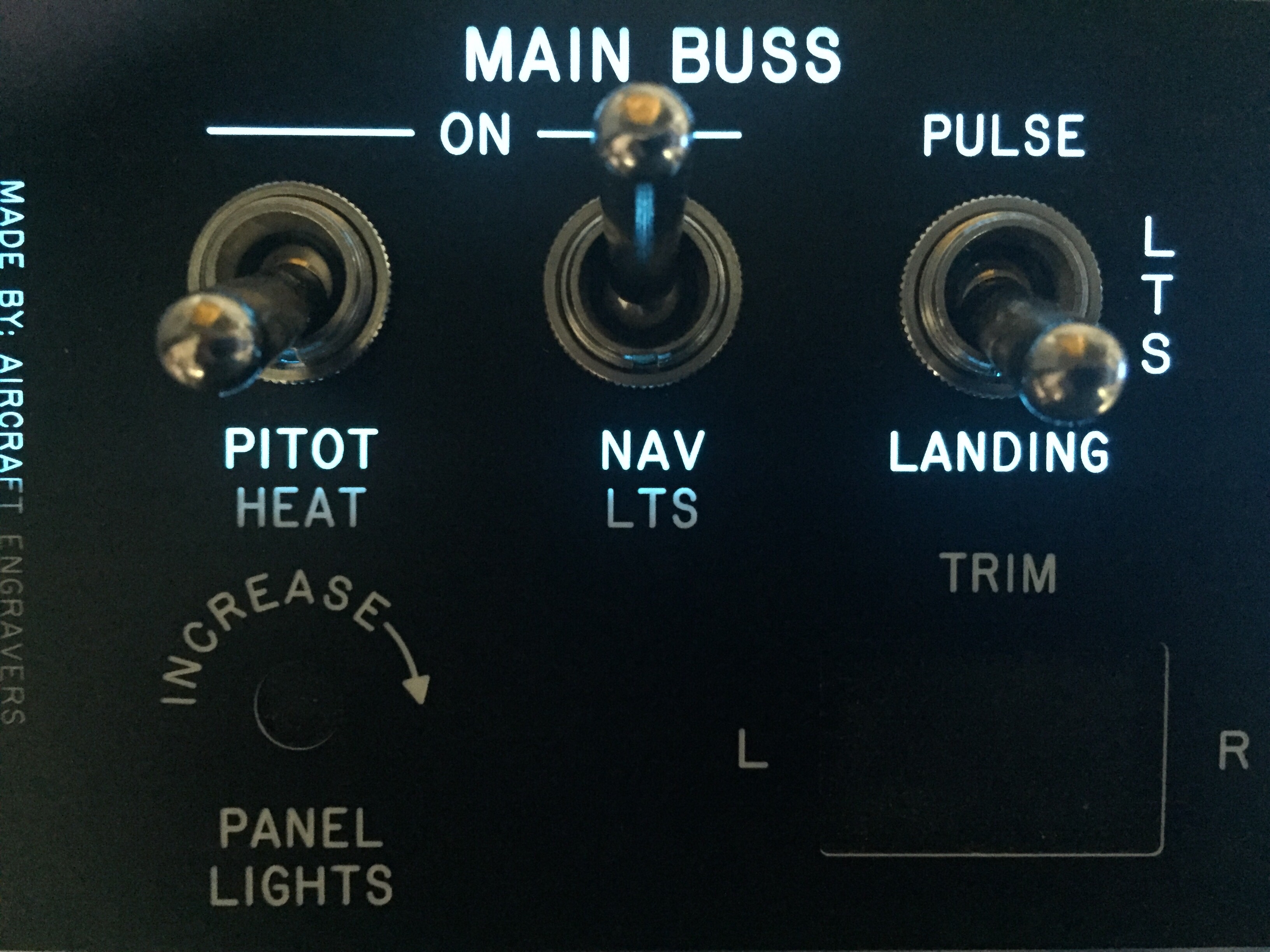
I ordered a test piece to experiment with in the shop and requested a sample of engraved acrylic from Aircraft Engravers.  Match made in heaven.  The EL panel glows nicely through the laser engraved markings and can be cut, trimmed, and hole punched for all of the switches and dimmers that need to go into the panels.  The transformer makes a bit of high pitch whine, but it will be drowned out in the airplane and a few flight tests in the Diamond confirmed that the transformer was not electronically noisy, only audibly so.

With a successful experiment, I set back to work in Draftsight to come up with templates to be cut and engraved by Aircraft Engravers.  AFS, who is building my panel, will still cut, paint, and label the four main panels.  This will be a presentable back up in case my EL project doesn’t work out in the long run.  I worked with an EL supplier from Etsy who has been awesome to get a proper prototype panel cut for the overhead console.  There are some limitations with the EL panels such as the power lead locations and two edges that have the contacts running along them not being able to be cut.  It was a bit of puzzle work, but in the end fairly simple to draft up and layout.  Aircraft Engravers cut and engraved the acrylic overlay for the overhead console panel and I was able to put it all together with switches to see how it looked.

I was so excited that I forget to specify which color, so Marc sent white.  No worries, as the production version will be a blue.  Needless to say, I spent a lot of time sitting in the dark garage flipping switches that weren’t wired to anything!  It’s a very elegant solution and a rather easy one at that.  For the whole cockpit, all EL panels will be wired together with one transformer and be dimmable through a rheostat.  I wanted all of the instrument panel to match, so I’ll be spending some extra money on acrylic overlays for the entire panel rather than just smaller panels around the switches, but it’s my plane and I’ll do what I want to!  Wayne at Aircraft Engravers has been great and is pretty excited at this working so well, as he may be offering more panels like this in the future.

So now, I have finalized the lighting panels and overlay panels for production.  I’m hoping the avionics arrive on time at the end of February for me to finish wiring and installing.  With my higher level of customization, I’m not using the AFS quick panel switches so I’ll have a bit more work to do than most quick panel customers.  I’m very grateful to Rob, Stephan, and all of AFS for hanging in there with me on this over the top instrument panel.  In the end, I’m confident I’ll have a real show stopper that I’ll be admiring for decades to come.

Back to heavy metal work

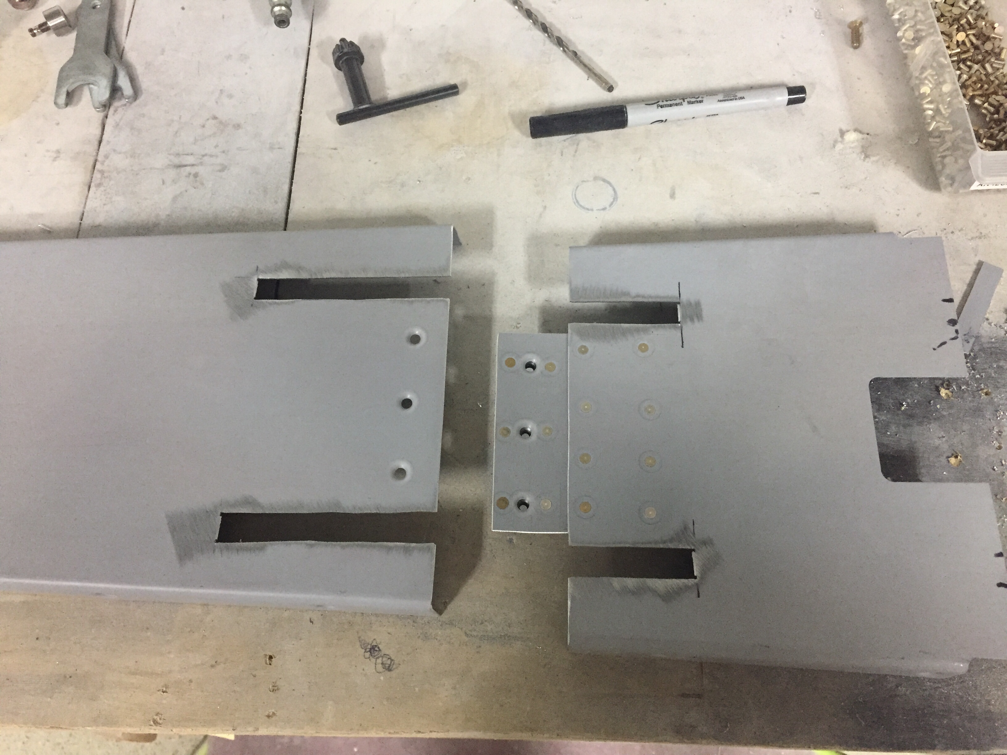
One task that I want to document for others I forgot to mention is modifying the tunnel cover around the Control Approach rudder pedals.  The cable attach arms are relocated inside the tunnel so slots need to be cut for them to move freely in the cover.  I measured their arc and marked the tunnel cover where I wanted to split it into two pieces.  Before cutting, I marked and drilled a center plate to hold nut plates which will allow me to screw the two pieces back together.  It was a pretty simple modification as was cutting the slots for the arms in each piece.  Again, I’m trying to consider maintenance and access down the road as much as I can.

I also took the time to modify the seat rails since I got the Aerosport seat levers.  Others have described this mod and it makes removal of the seats a snap.  Step one is to remove the delrin guides from the seat bottoms and trim the first 1 ½” off followed by reinstalling them.  This allows the seat to be slide rearward on the rails and then tilted around the flap tube cover with the necessary clearance.  I then removed the aft rail stop and drilled through the rail into the plate below.  Installing nut plates below the plates lets you put bolts in place of the screw and nut on the stop.  Now, I can get to the bolts from the top down eliminating the need to reach under the seat plate to get the lock off, allowing the seat to slide freely rearward.  It all makes sense when you look at it.

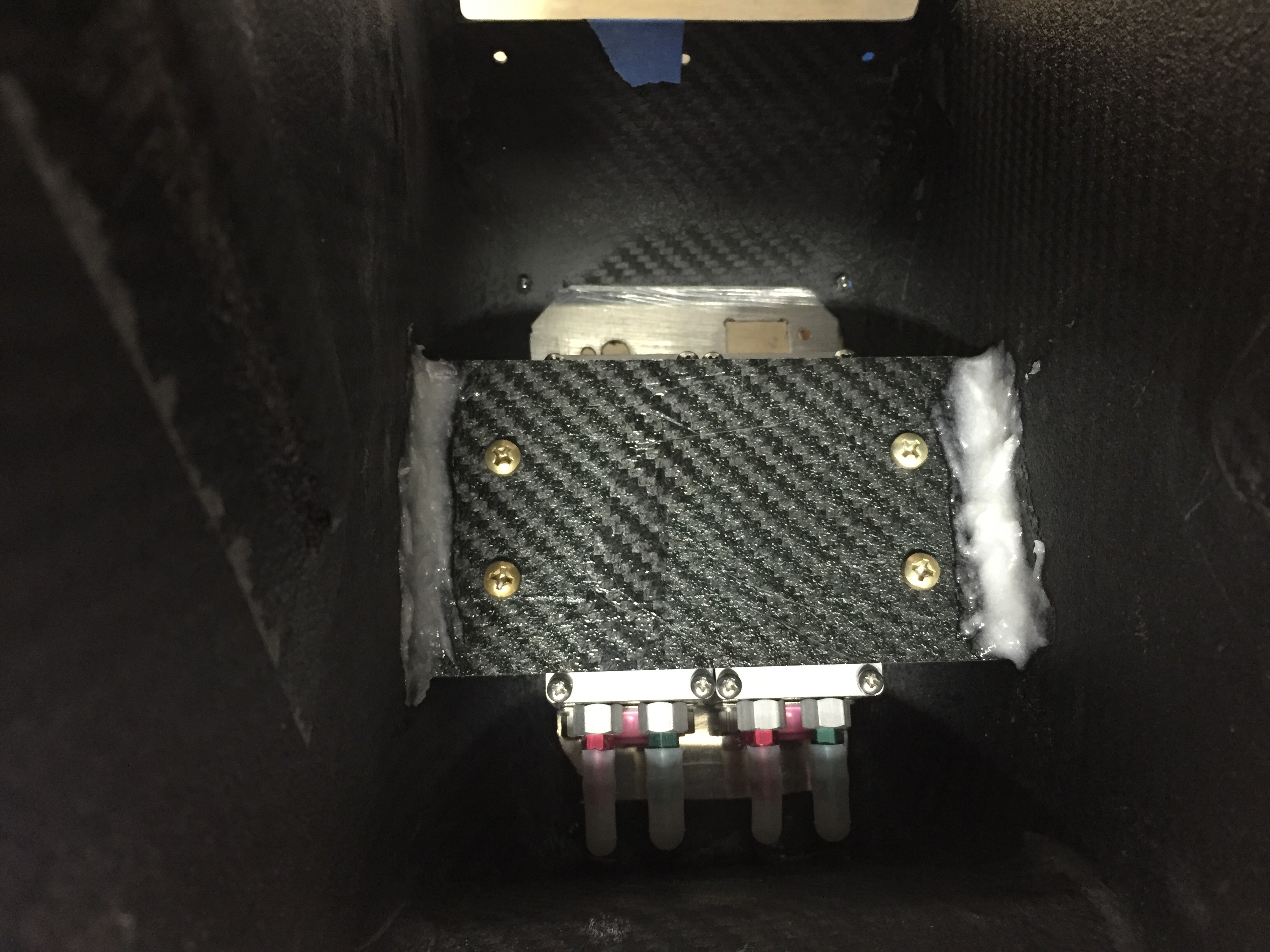
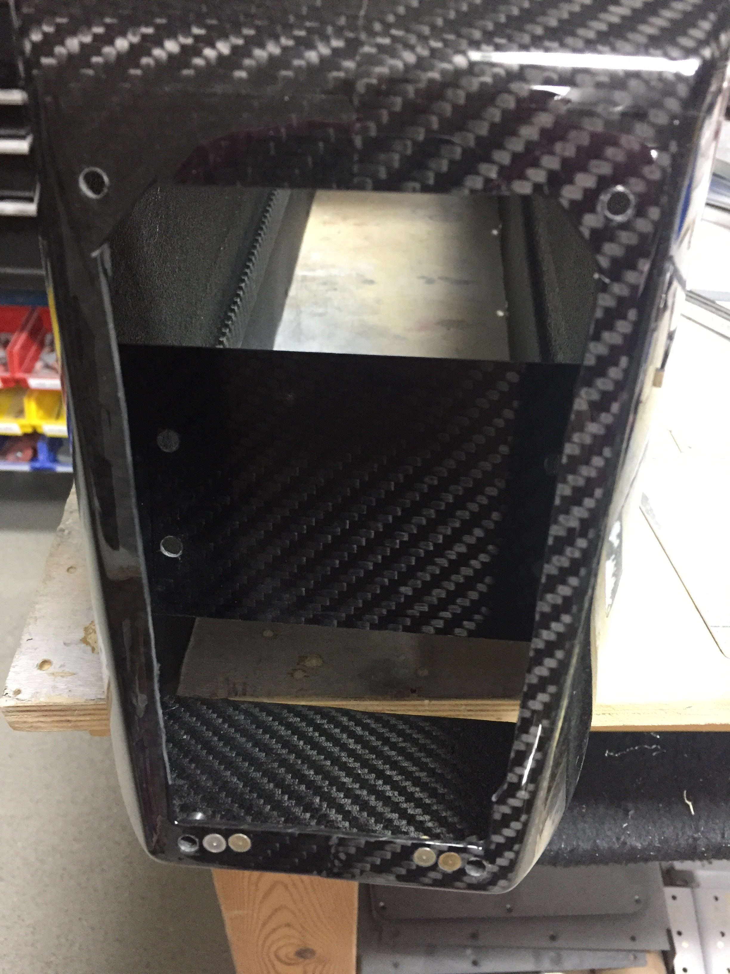
I’m trying to knock out some little side tasks along the way now in the spare time.  I used some excess epoxy from a door filling session to install the front vent NACA scoops.  I drilled a few holes and used clecos to hold them in place while the flox cured overnight.  I don’t have proseal and didn’t want to use any silicone on the area since it will be painted.  With minimal flexing and a good scuffing on both surfaces, I am confident the epoxy will hold these just fine long term.  The scat tube will have a short run from there to the Aerosport vents that I installed in the instrument panel.

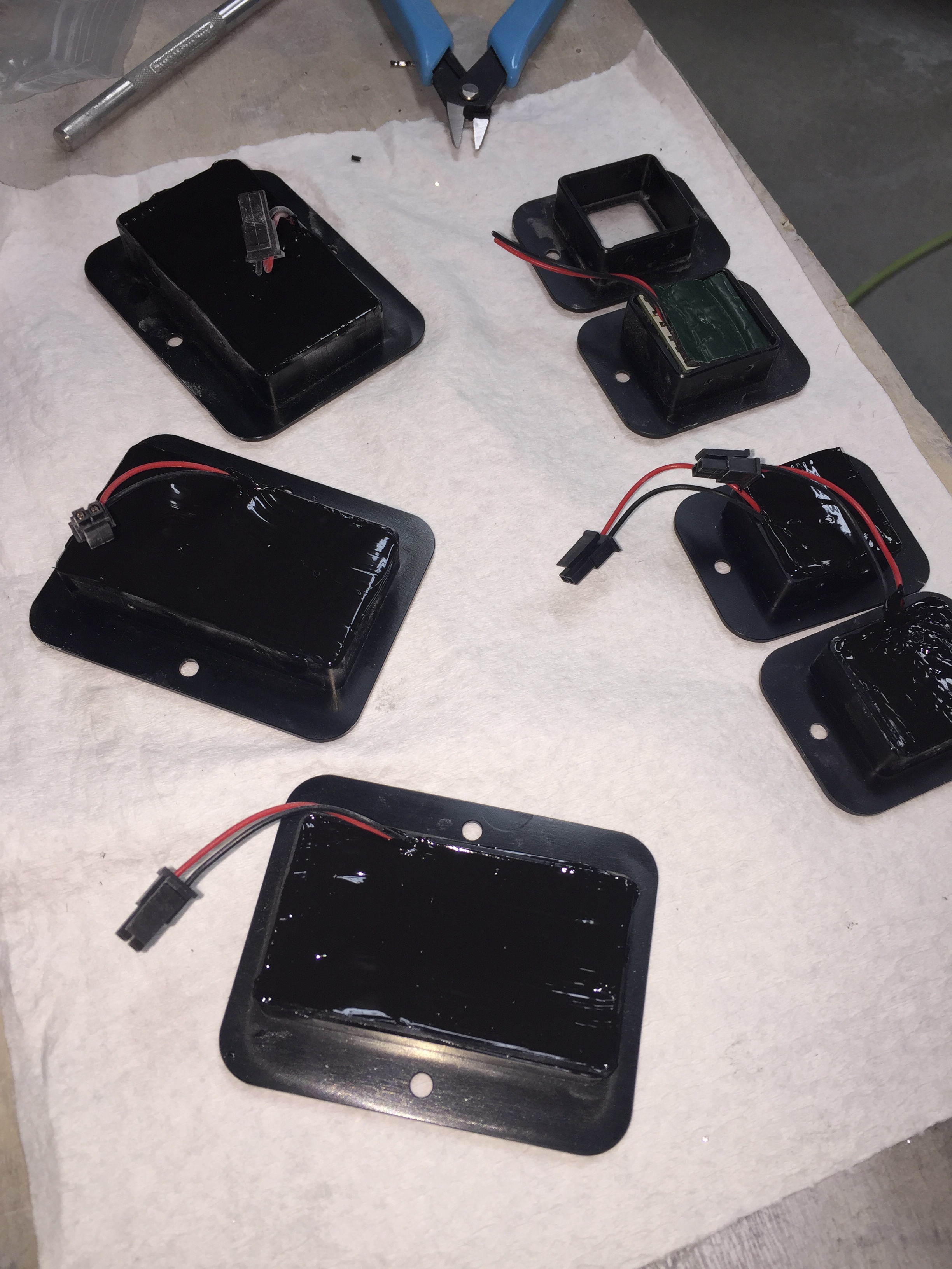
I also performed a quasi service bulletin from Sean at Plane Around.  When I received the lights from him for the overhead and doors, several had bad boards which he promptly replaced.  I got a call from him with an interesting finding.  He used a brass wire over a piece of foam to hold the LED boards inside the aluminum and plastic housing.  He found that in a few instances, the wire was touching the board and shorting out LEDs.  Awesome service!  He called and suggested using a different method such as silicone which is an easy solution.  I removed all of the installed lights and completed the rework after ensuring all LEDs checked good.  I took the opportunity to install the micro molex connectors on the remaining few assemblies as well.

Service bulletin complied with in accordance with published guidance, OPS check good!

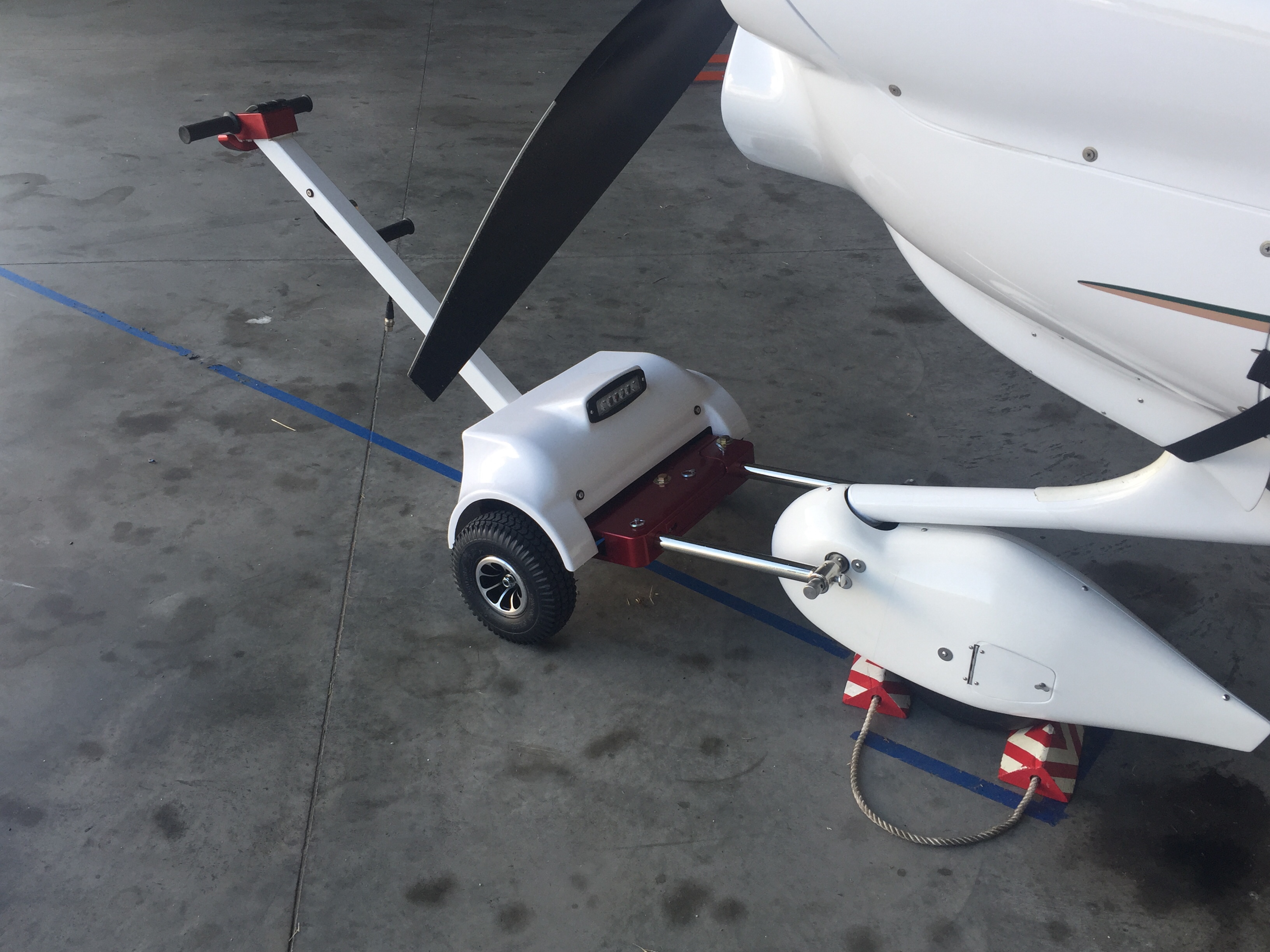
And finally, another cleanup item to mention was the addition to the hangar family.  While she hasn’t been officially named, our new Best Tugs Alpha 2 arrived!  I ordered this at OSH last year to use on the DA-40 we fly now and for long term with the RV.  It cost a pretty chunk of change (plastic, let’s be honest) but man is it nice.  It will save my twice-operated on back for years to come and is really handy to maneuver the airplane around.  It took a bit of practice one afternoon but now it’s just like pushing a shopping cart!  I requested the smooth cover with the intention of having it painted by Jonathan to match the RV but didn’t realize the red anodizing was going to arrive.  Oh well, not the end of the world.