This Bird is Squawking

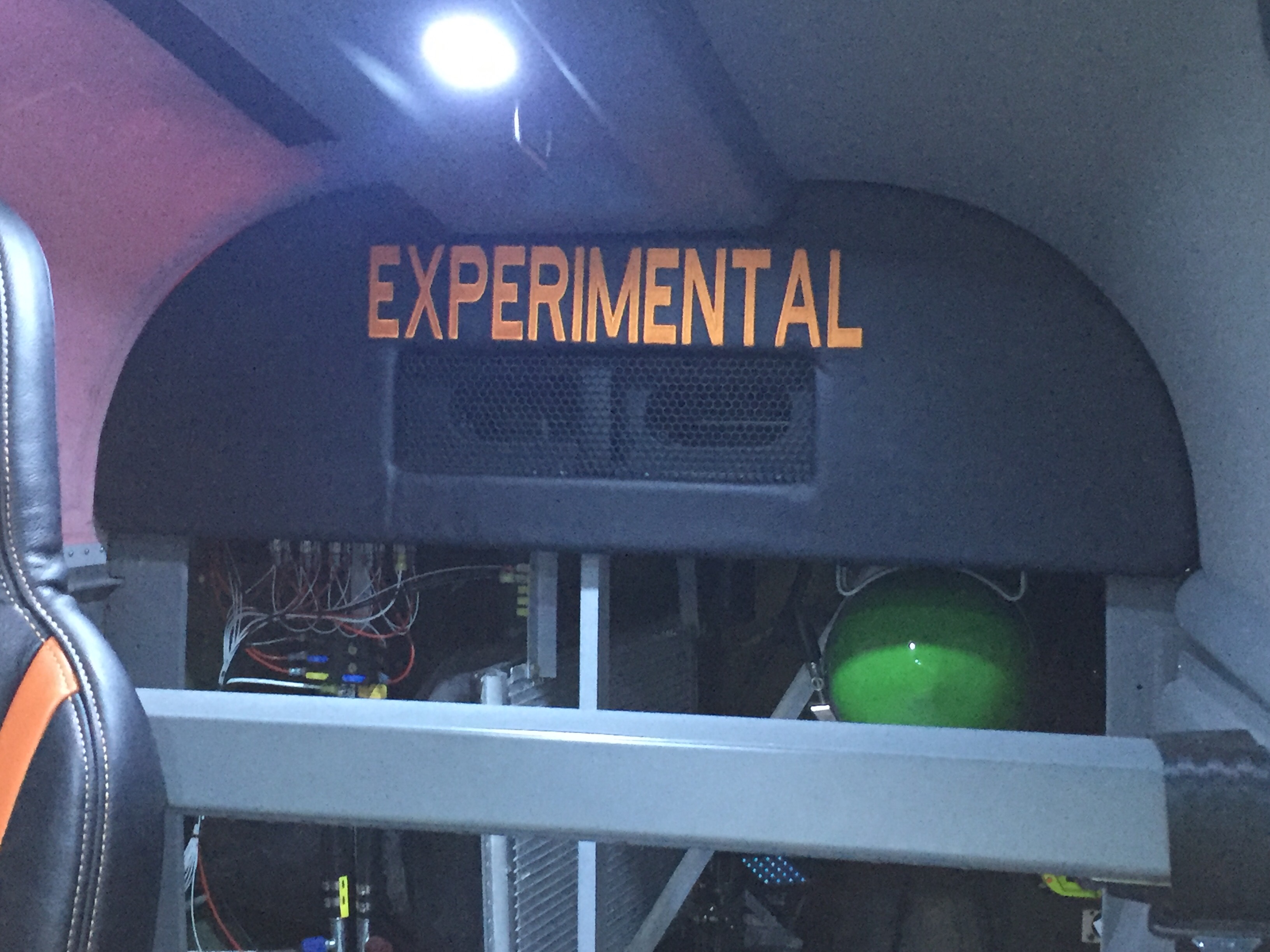
I will document the biggest and most annoying things wrong with the airplane during the test flight here but do not plan on blogging about every repair or modification to the airplane. Mainly because I’d have to become a full time writer.

The flight tests went fairly smoothly and I finished the 40 hour phase 1 in under a month. Most of my issues were builder caused, I must admit. Either a rework or bad soldering, decision making or lack thereof, and a few “that’s good enoughs” that came back to haunt me were to blame.

I tracked these by creating a list in my phone/iPad that I could check off as I corrected the issues. The list kept growing for some time before it started getting checked off. It’s worked really well for me and actually motivates me to complete all the repairs or adjustments to get the check boxes checked. I can also make group entries into the logbook to keep track of the work.

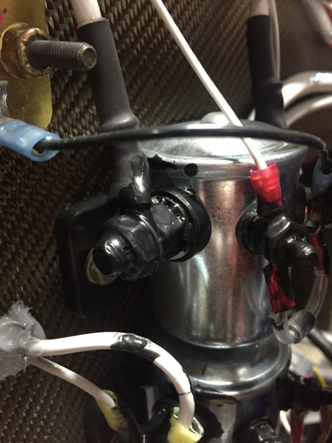
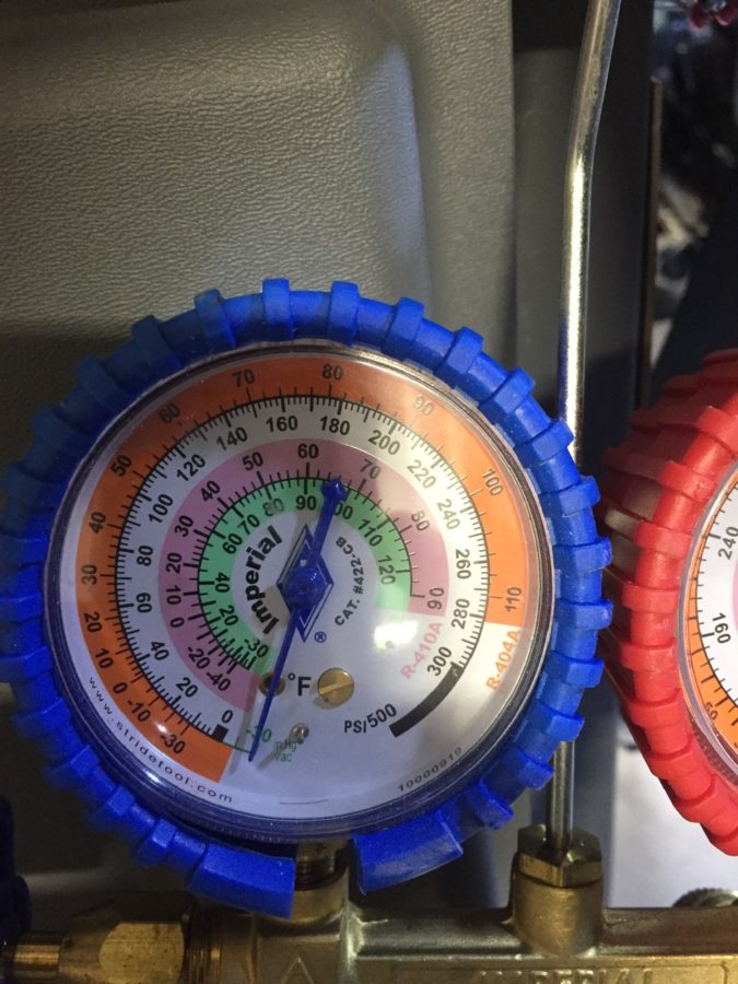
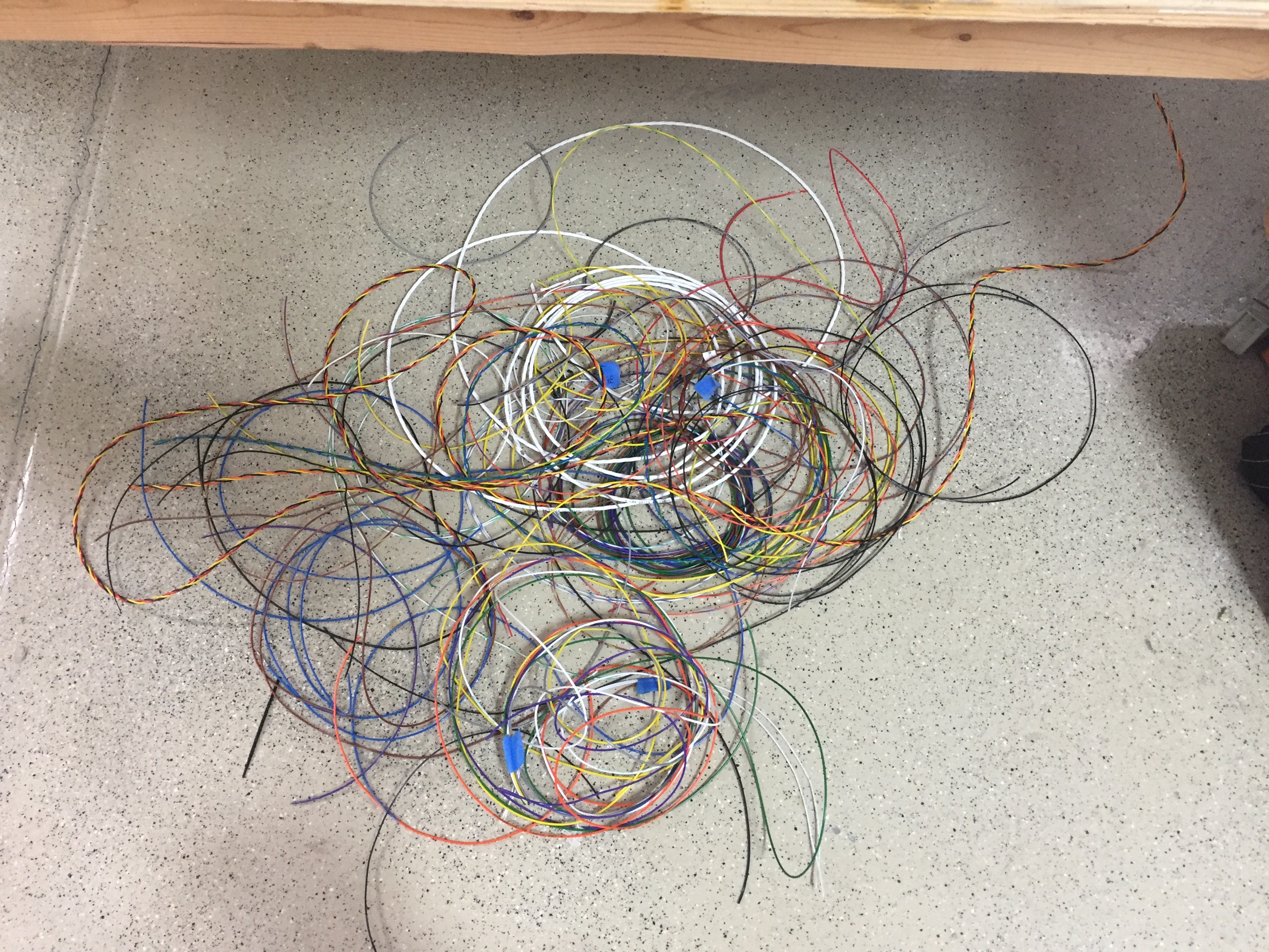
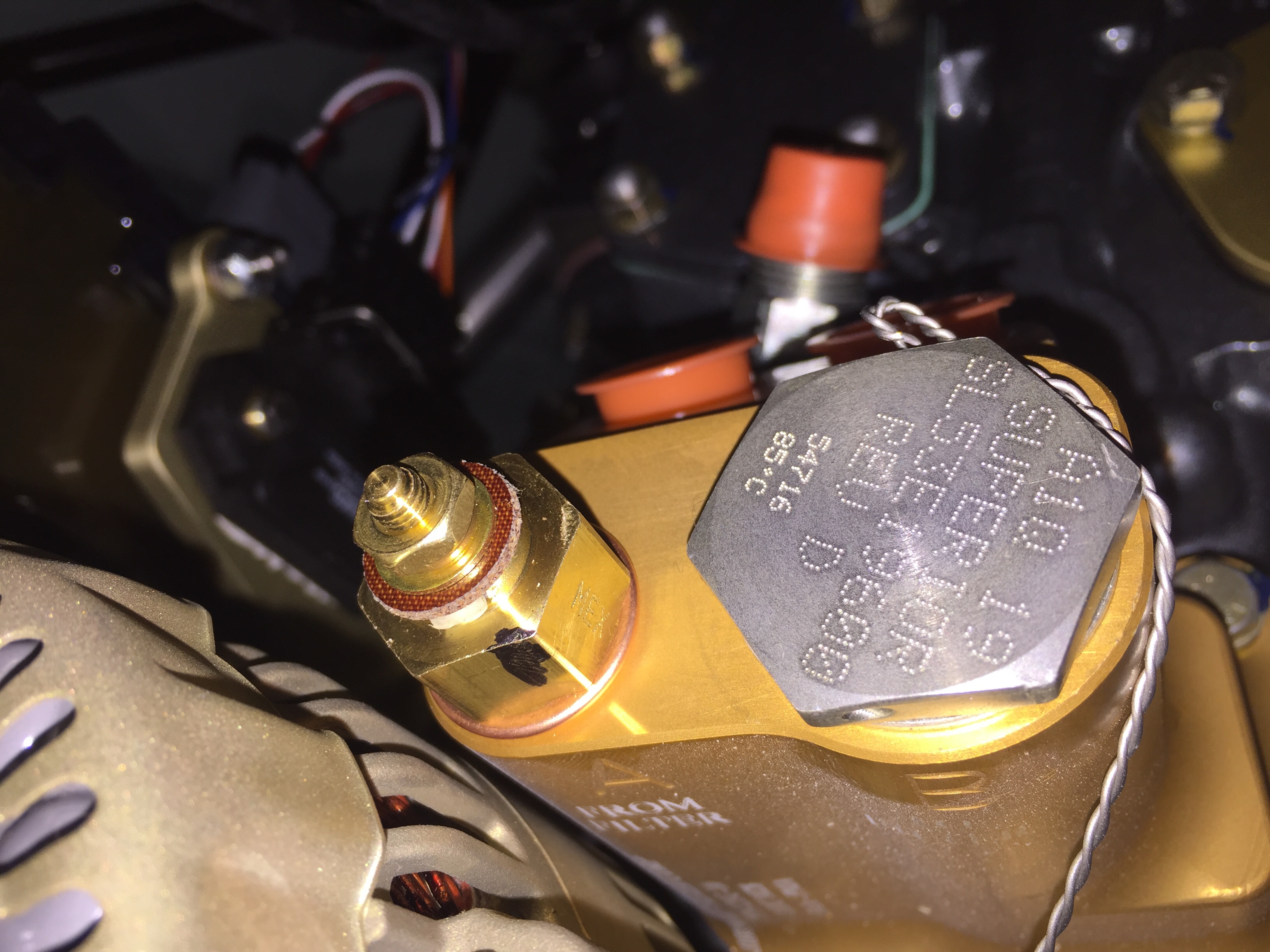
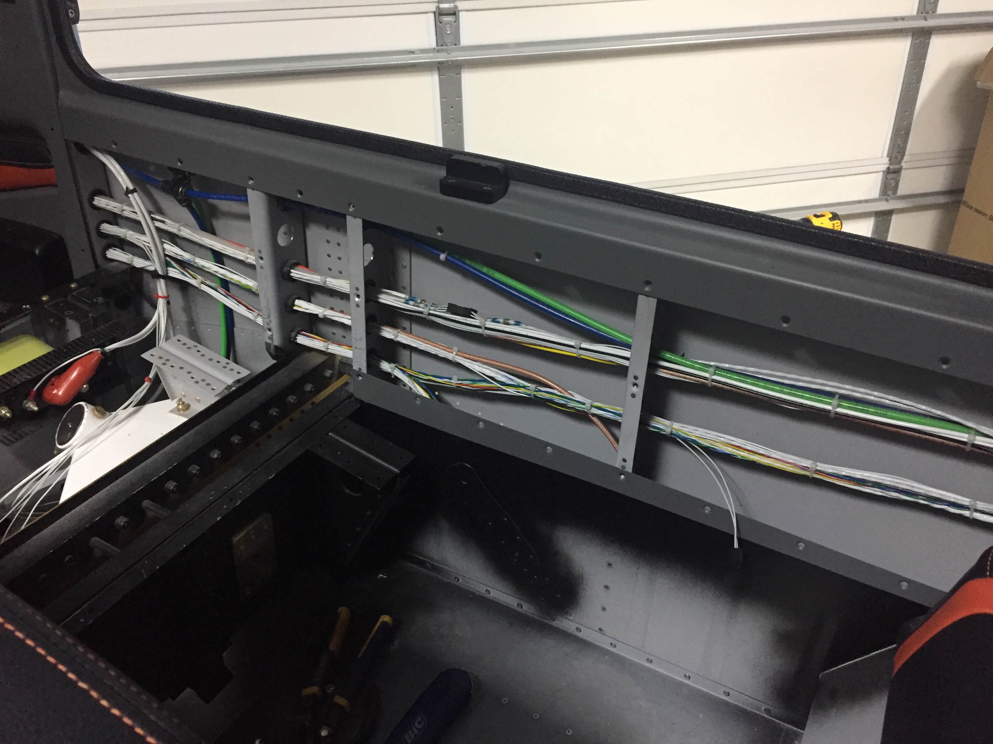
I found that I had a lot of electrical gremlins throughout the first bit of flying. Solder sleeves are amazing little buggers that are notoriously difficult to use correctly. I used sparingly while building, but they still bit me a few times. The problem is you think the solder ring has melted completely but it hasn’t. The connection will be good until it’s subject to some vibration and then all kinds of weird things happen. My oil pressure spiked to 200 PSI, multiple random annunciations based on my discrete inputs, and a few others due to the solder sleeves. And I only have about 10 in the whole plane! I will use them now if I have good access to the connection, but if not, I’ve found using Dsub pins and heat shrink as more reliable.

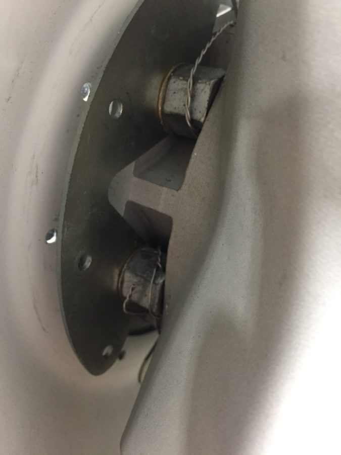
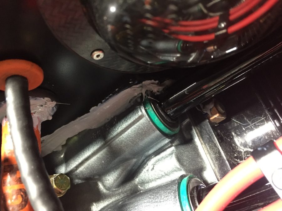
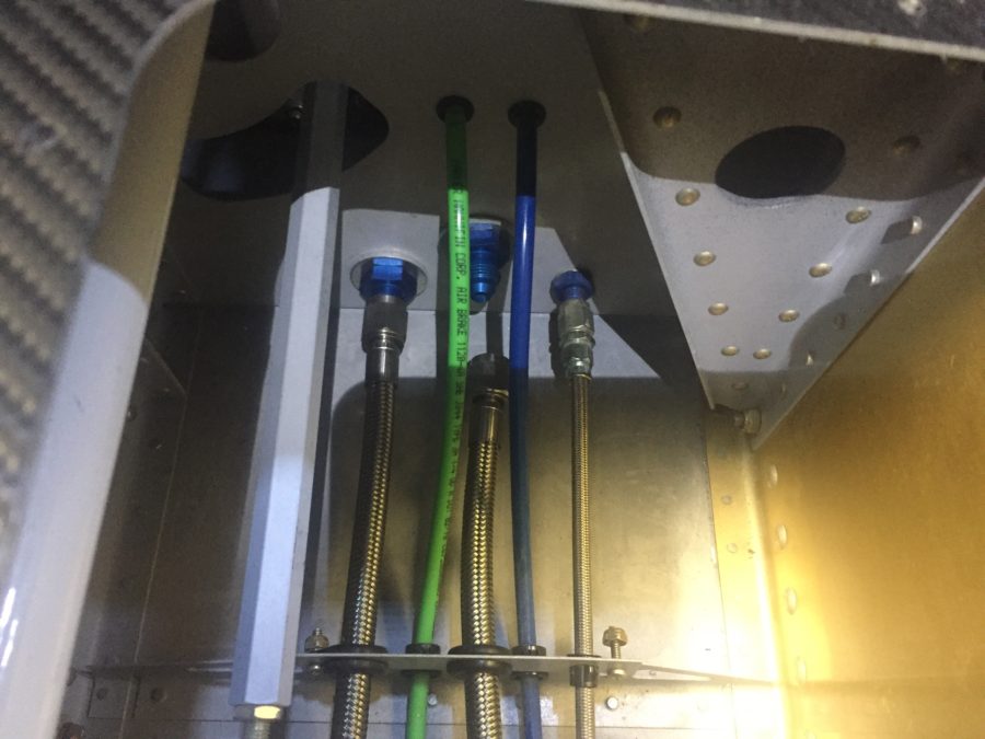
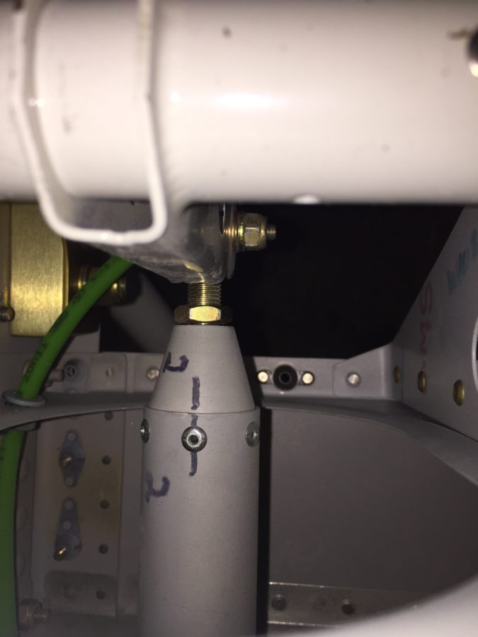
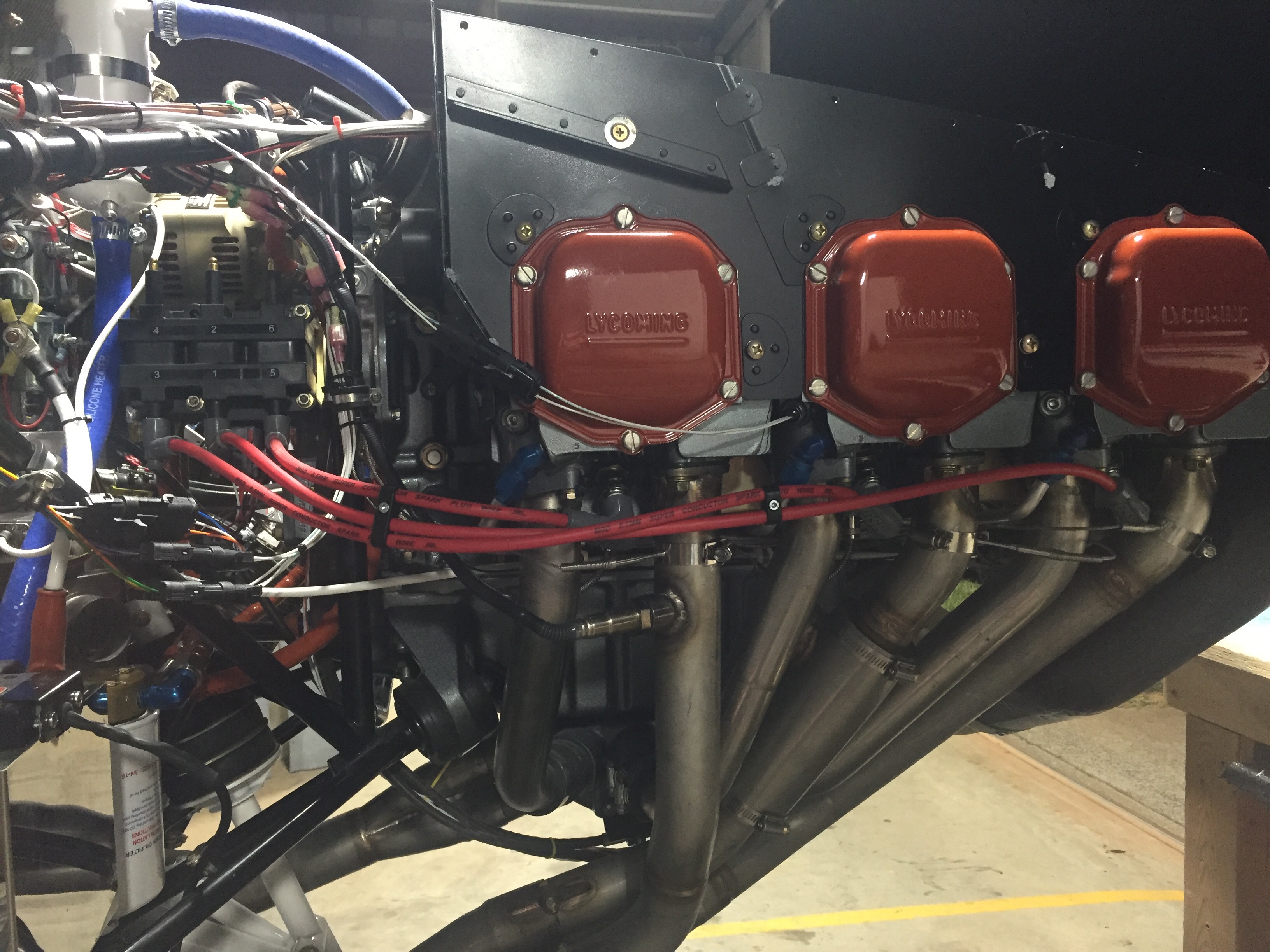
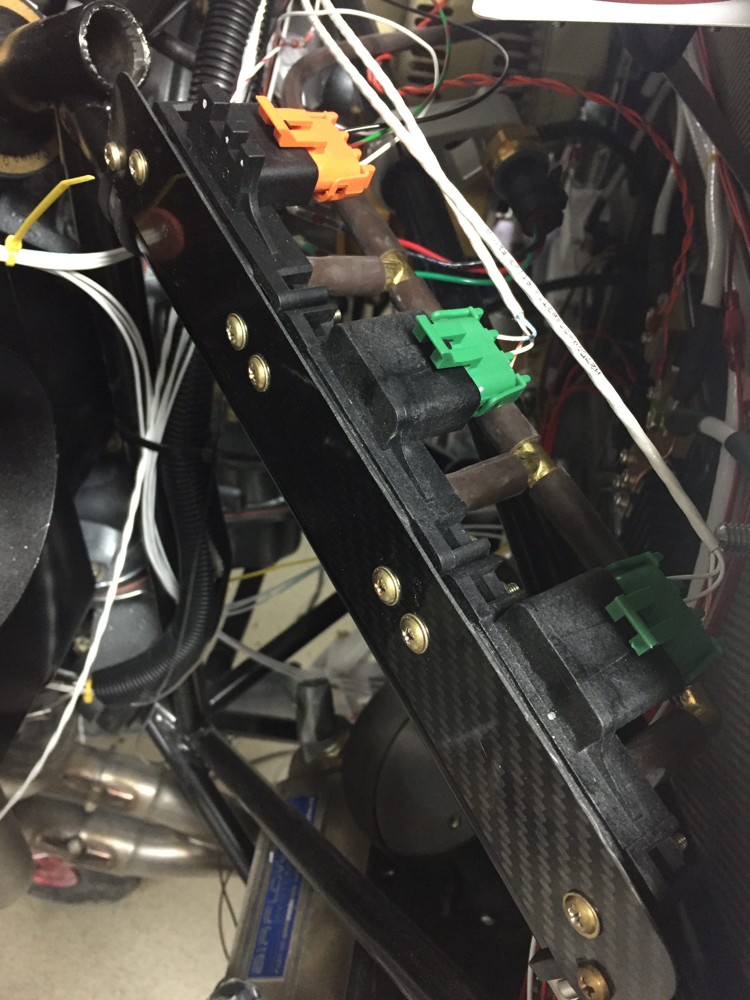
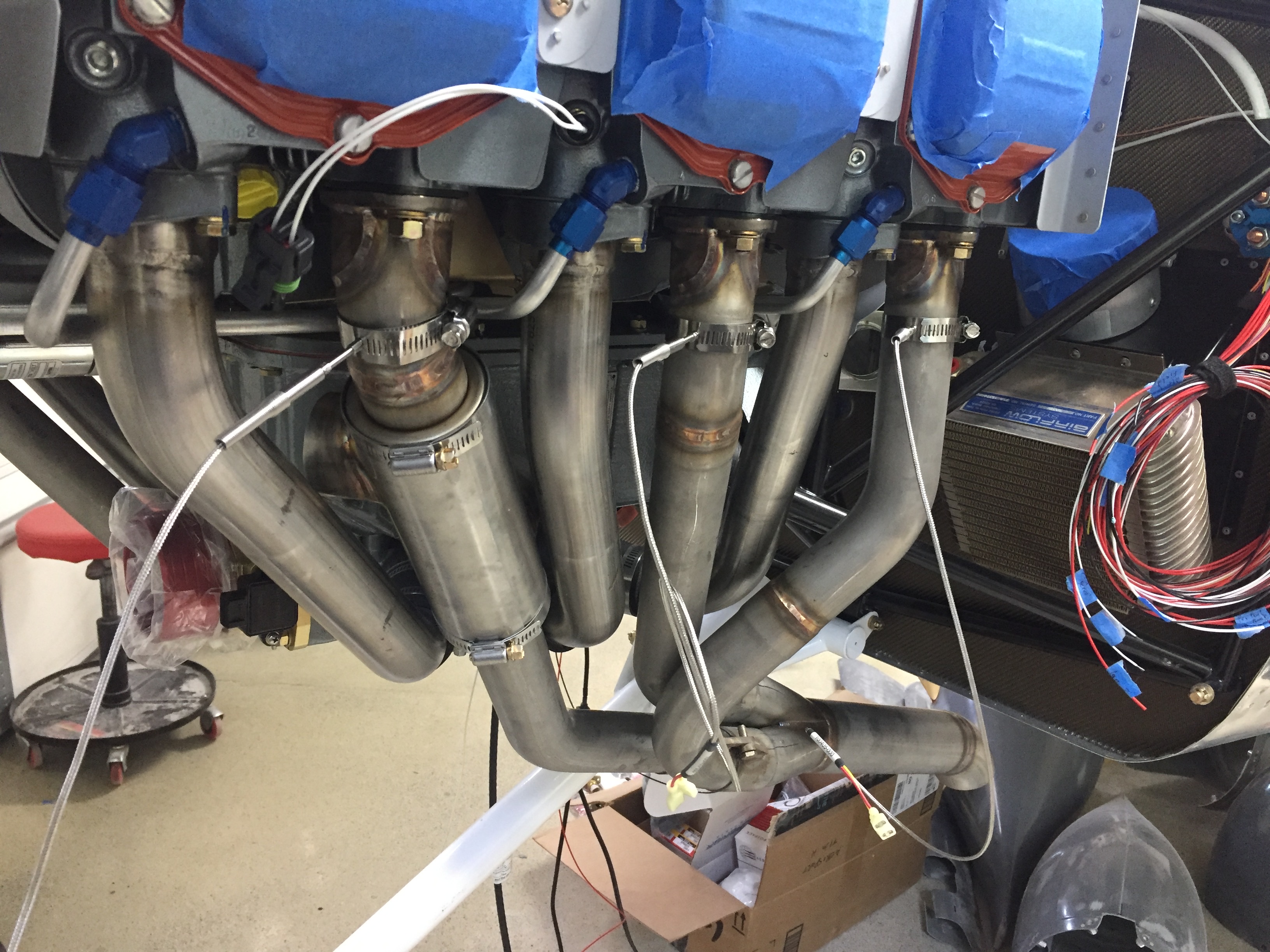
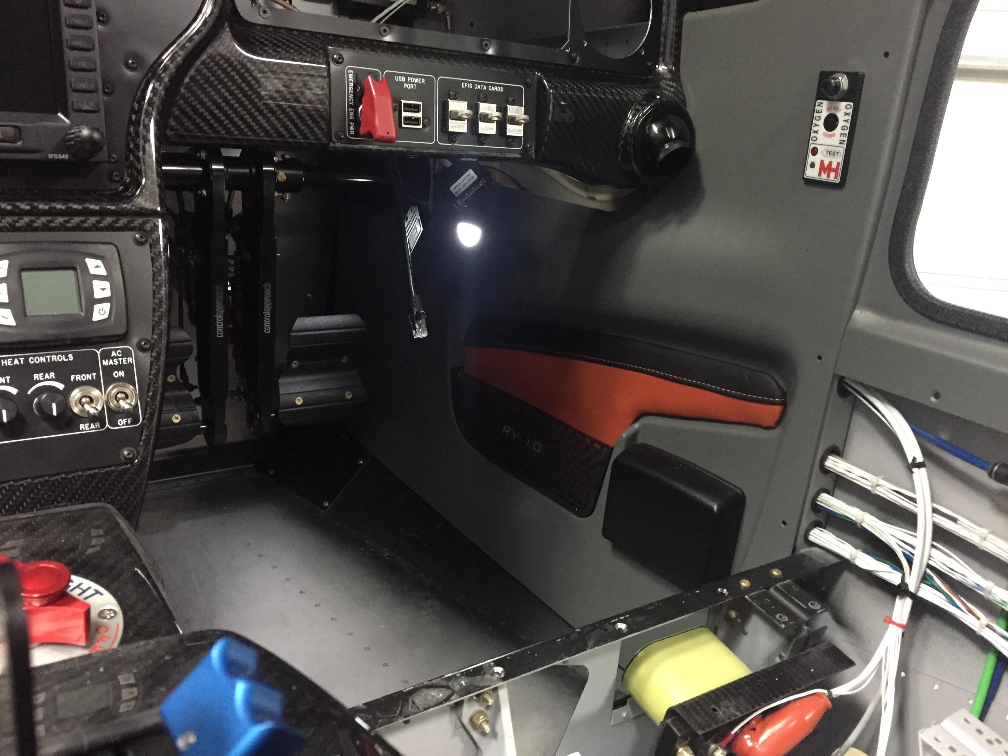
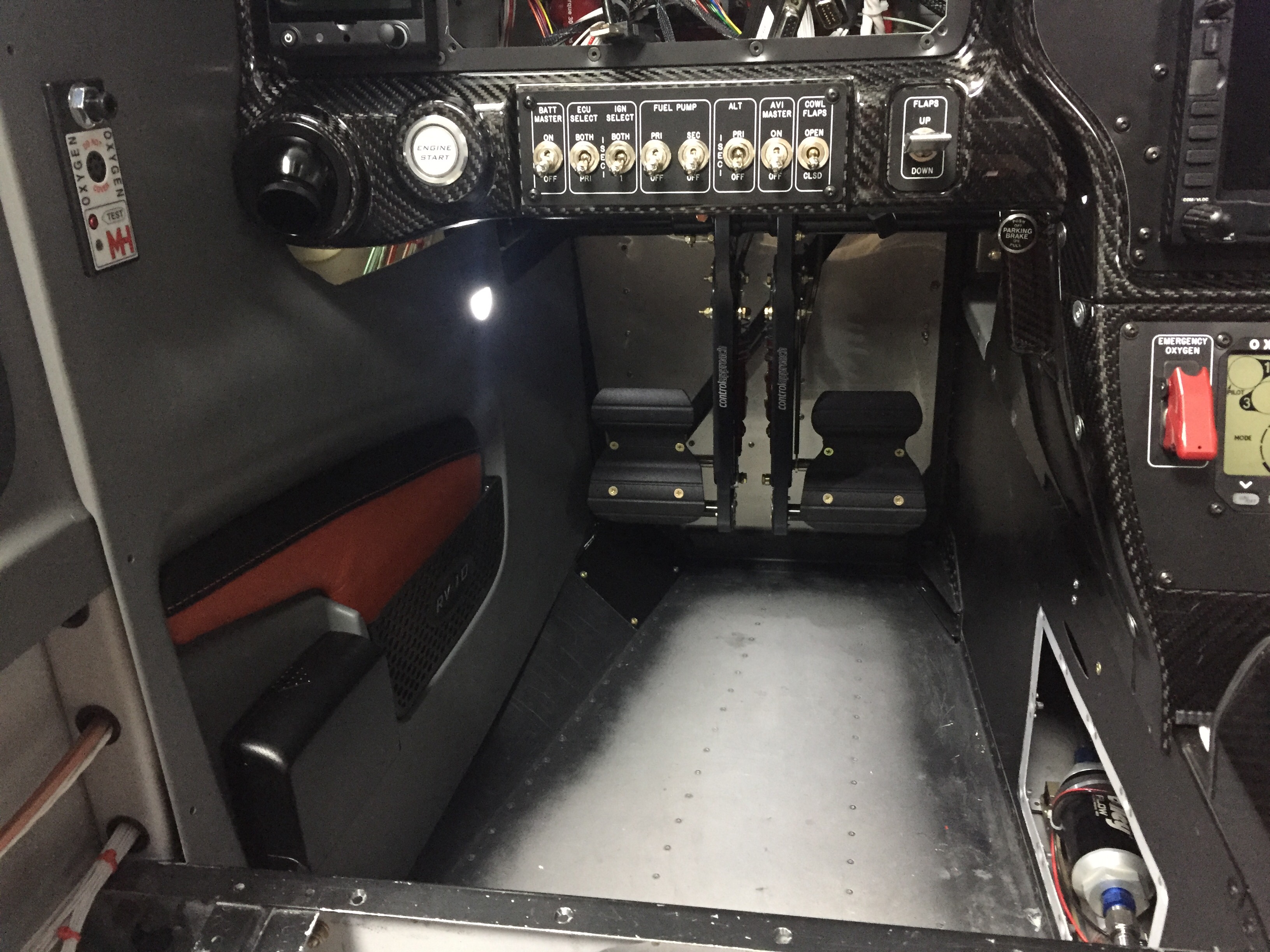
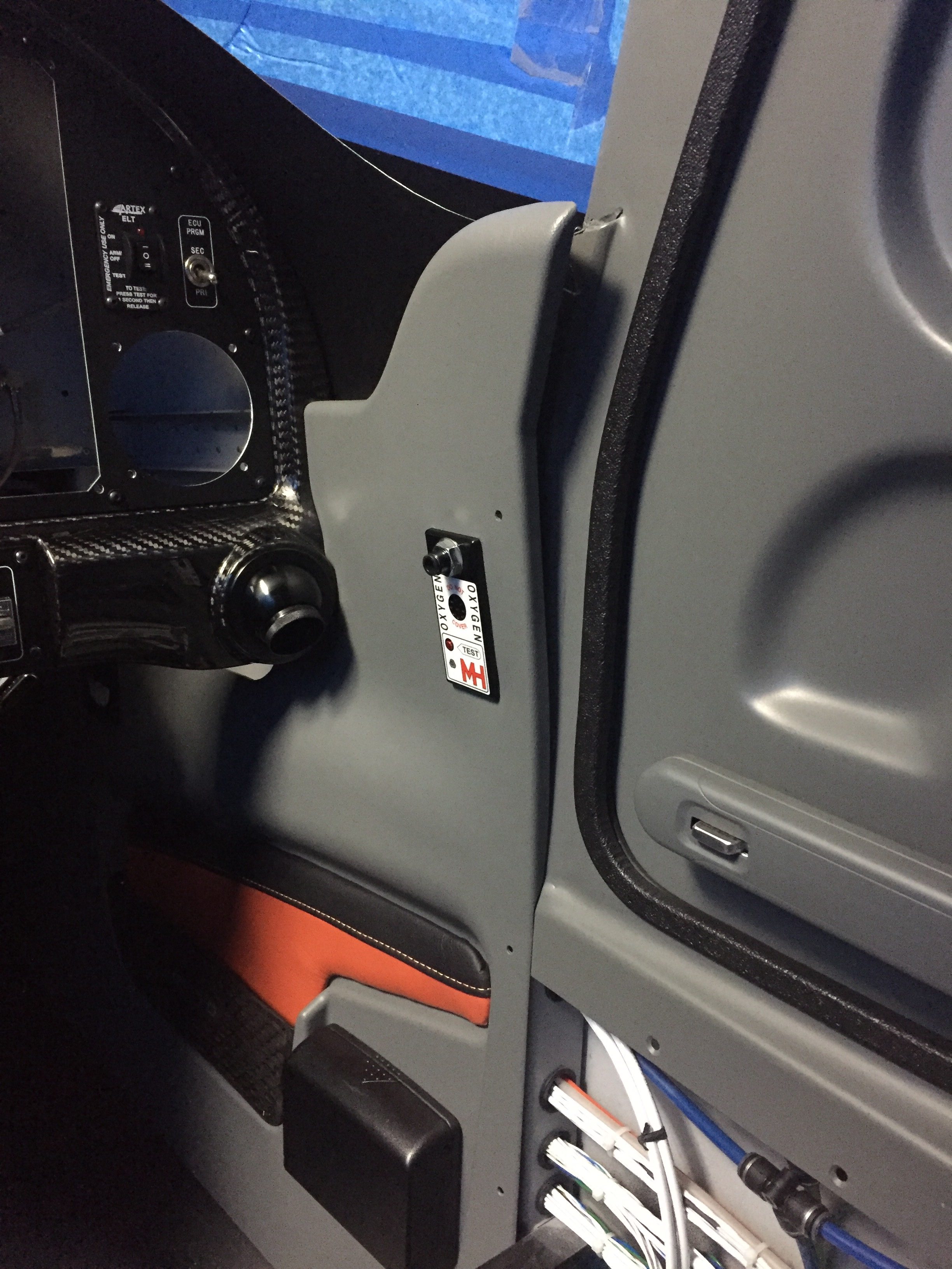
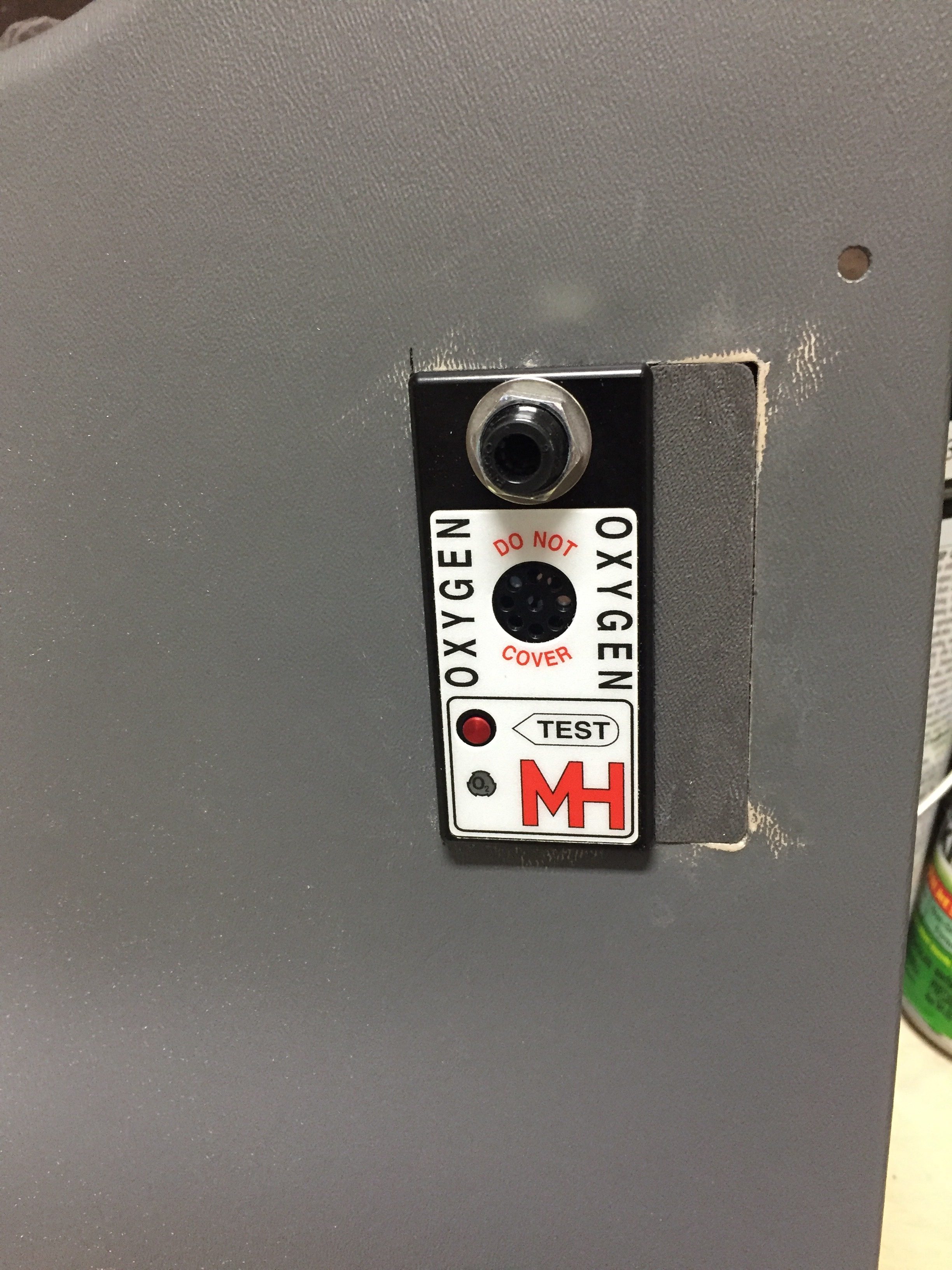
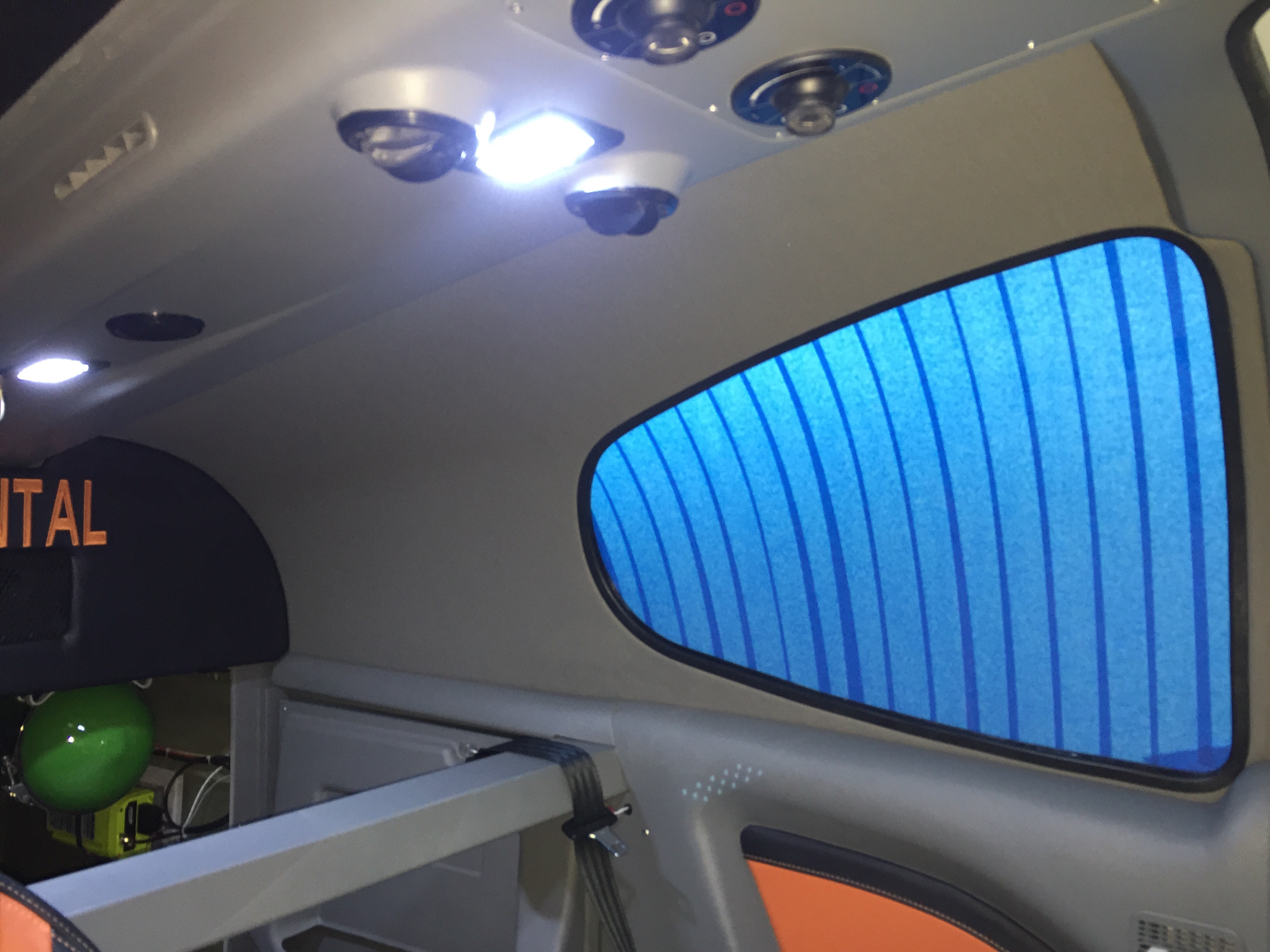
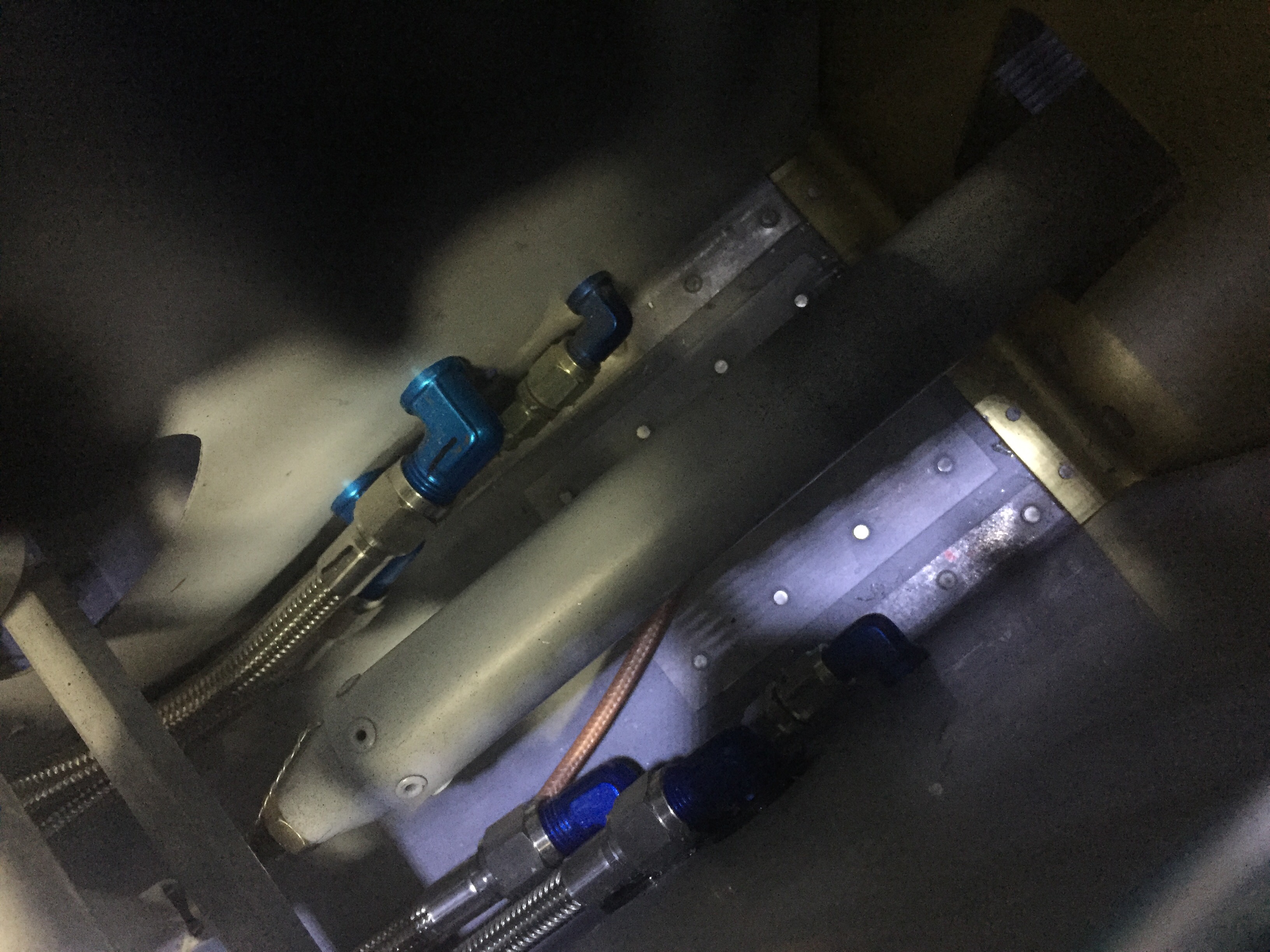
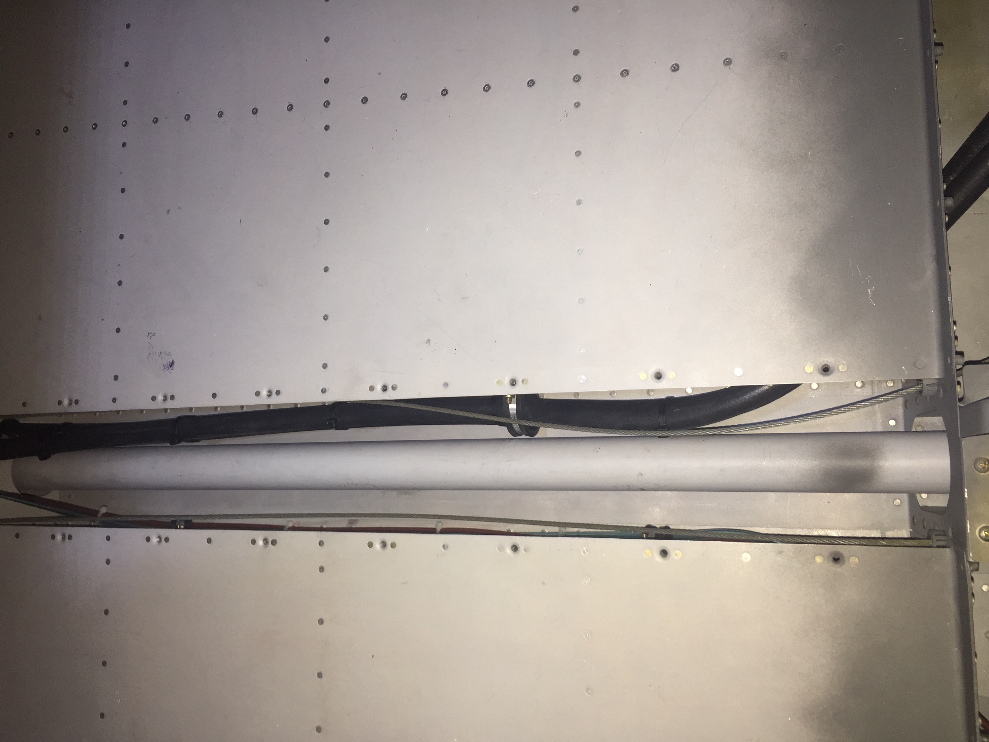
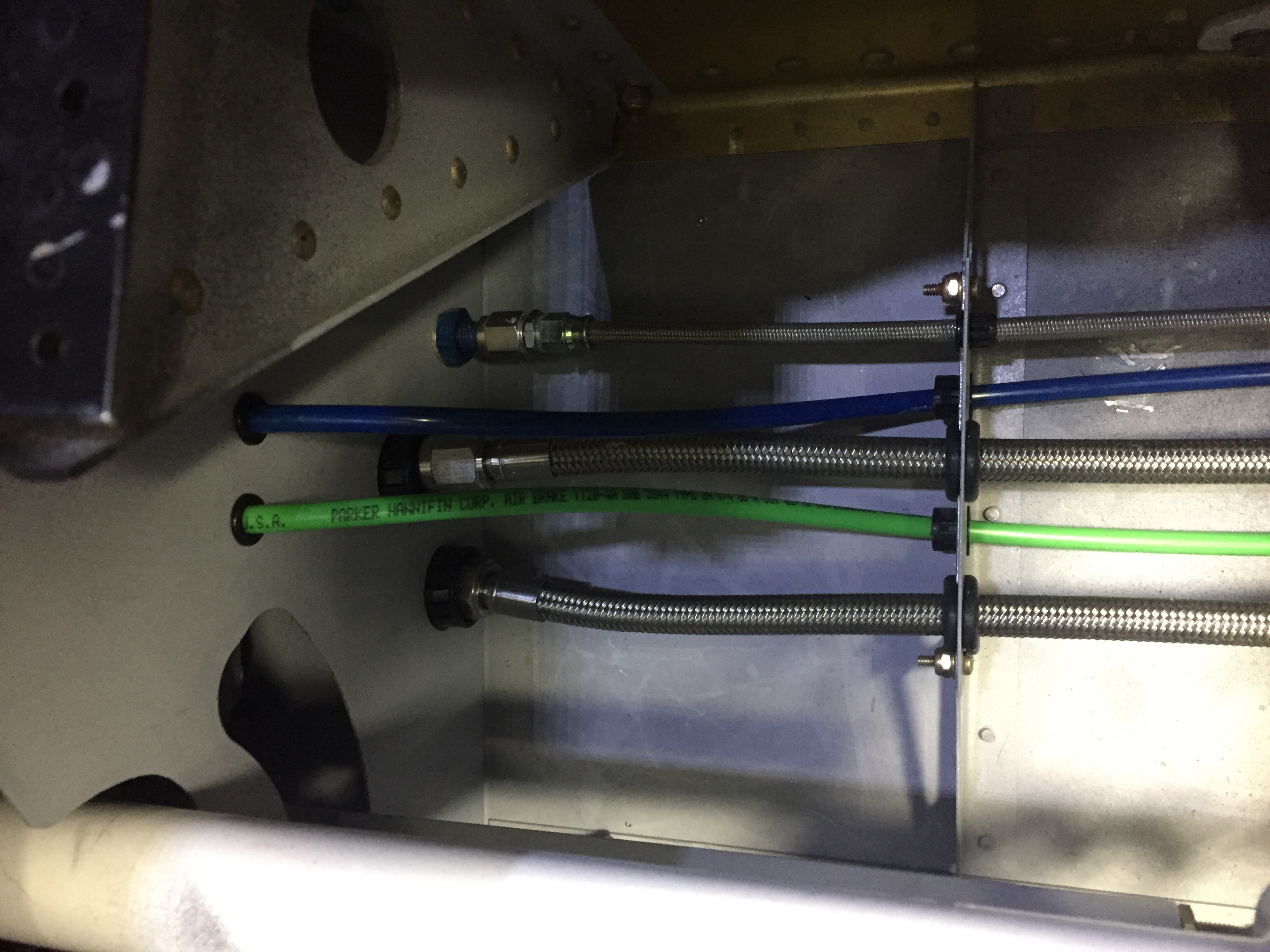
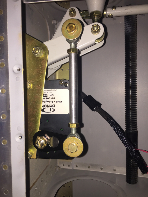
I had to reposition my EGT probes, as I realized they blocked 5 out of 6 spark plugs. I had a master cylinder bolt leaking just a bit. Lots more clamps and zip ties were installed, mostly firewall forward, to avoid chafing after a few oil changes and seeing where things moved a bit too much. I had to replace the autopilot pitch servo due to a service bulletin, roll servo due to slipage, and had to reinforce the rudder trim tab mount to get it to work effectively. I chose to rewire a few engine switches and add a engine master switch, which I should have done in the first place. That all neccessitated under the panel work, a new switch panel overlay and backlight sheet. The oxygen system leaked above 1200 psi (loose connection), and a few adjustments to the door light switches have been made.

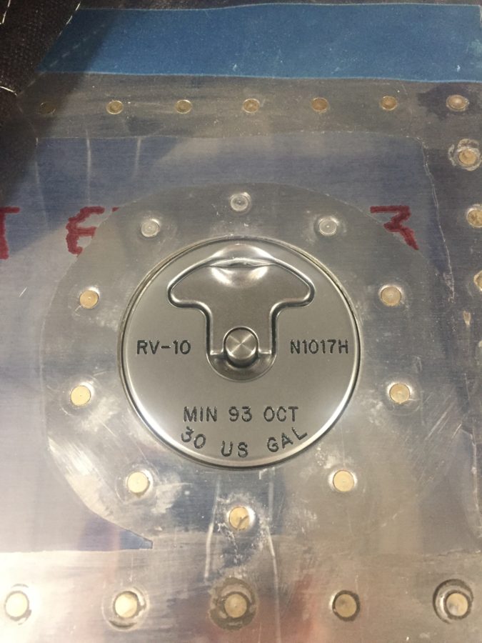
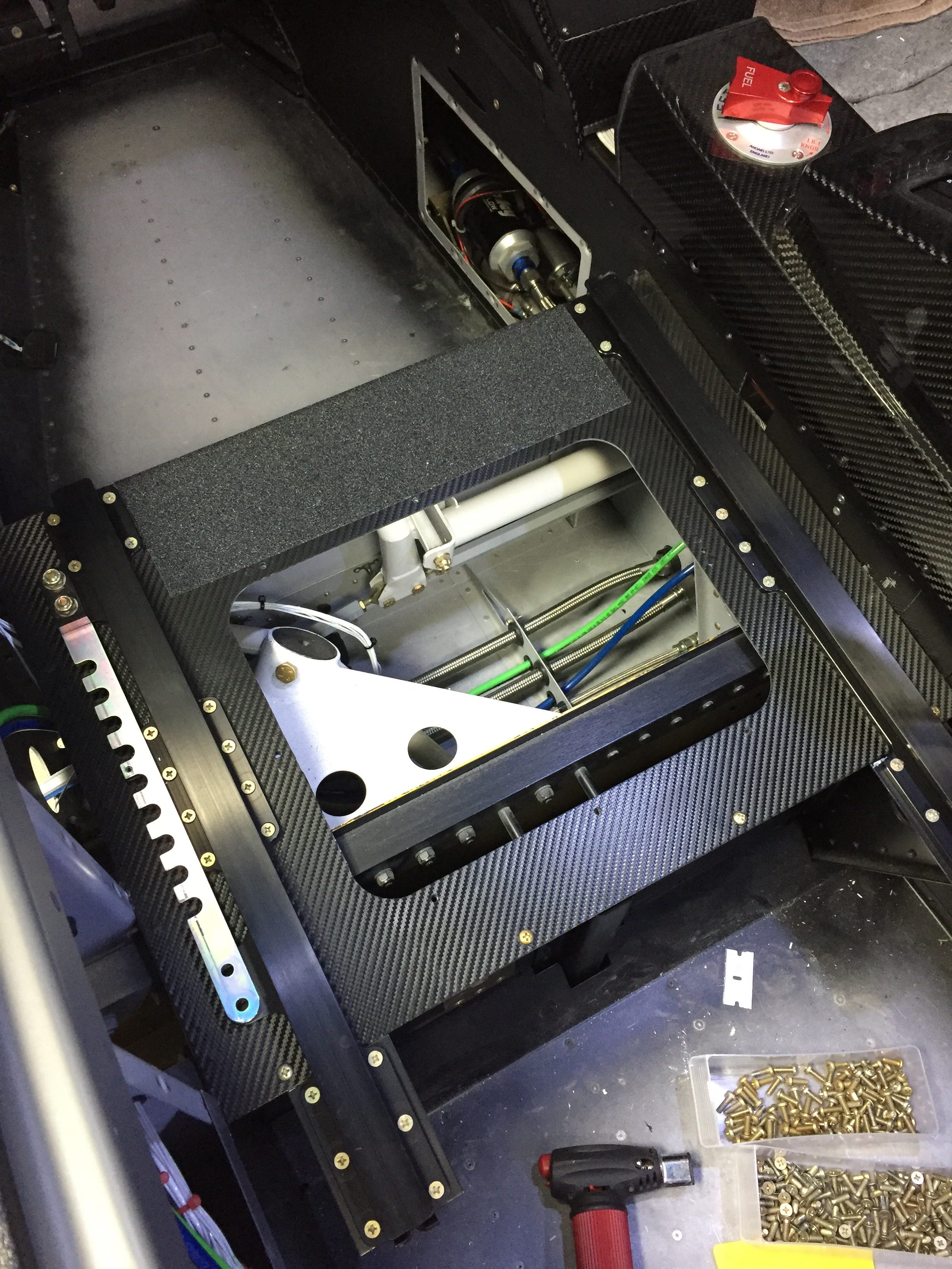
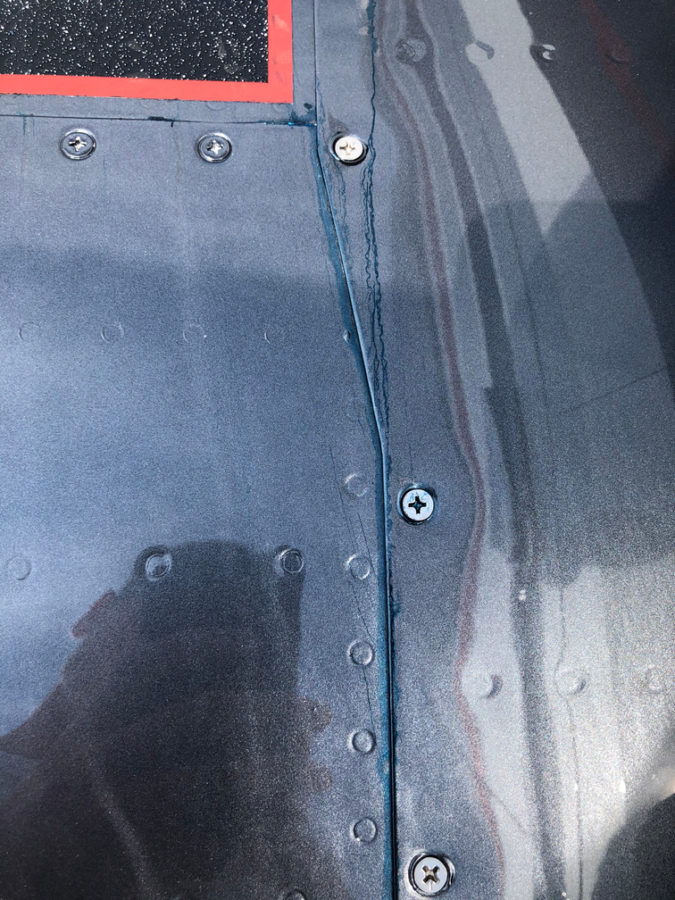
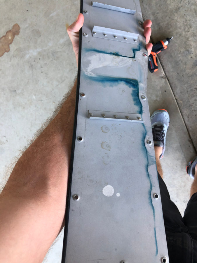
The biggest squawk is a leaking fuel tank. I am getting ahead of myself on the blog, but this was discovered post paint unfortunately. Turns out a little weeping rivet that I discovered prior to paint and thought I had fixed with the Loctite trick wasn’t fixed. In fact, it wasn’t a weeping rivet, but a pinhole in the sealant on the rear baffle. Fortunately, I spent an entire day and was able to use my borescope to provide a view and a coat hanger/tube of pro seal to apply sealant and fix the leak without taking the tank off. Not a fun job.

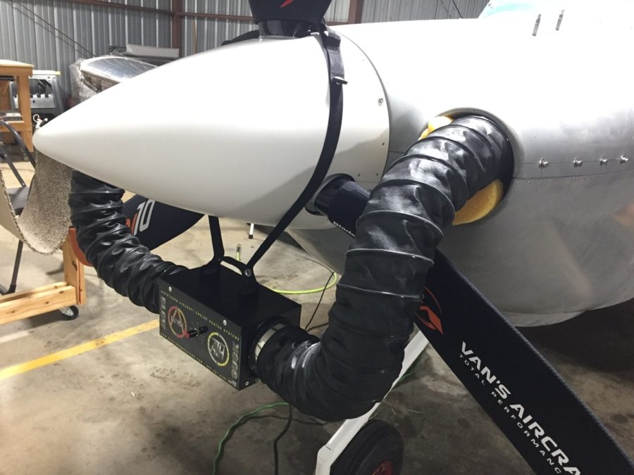
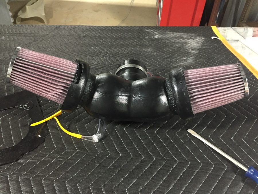
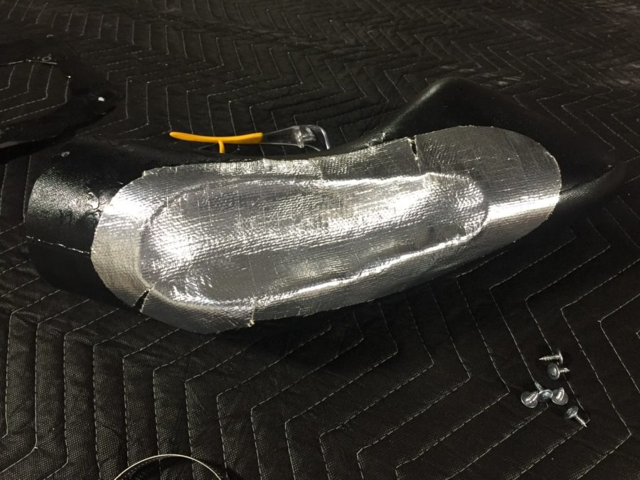
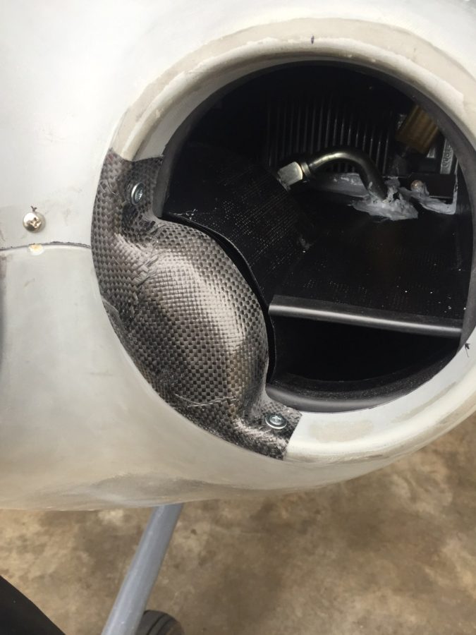
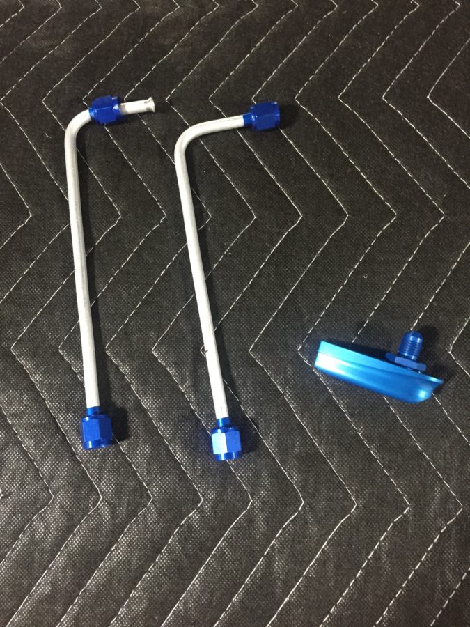
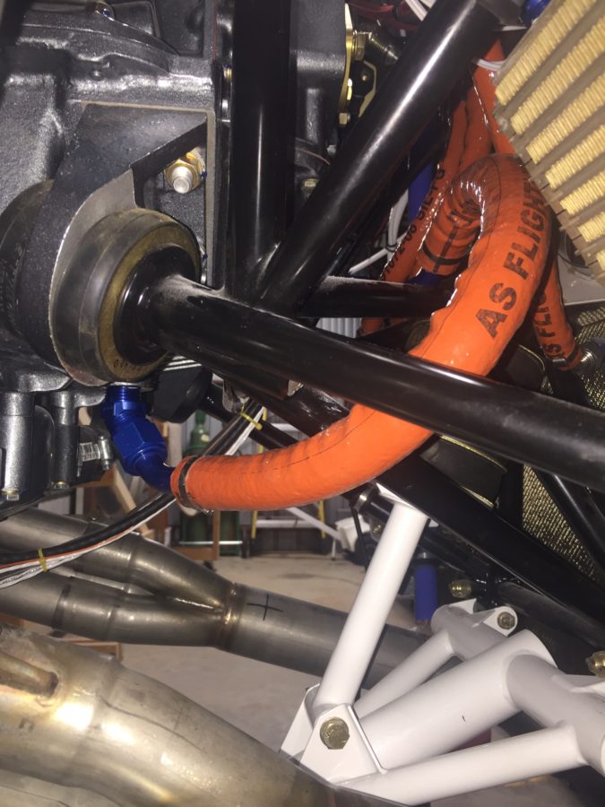
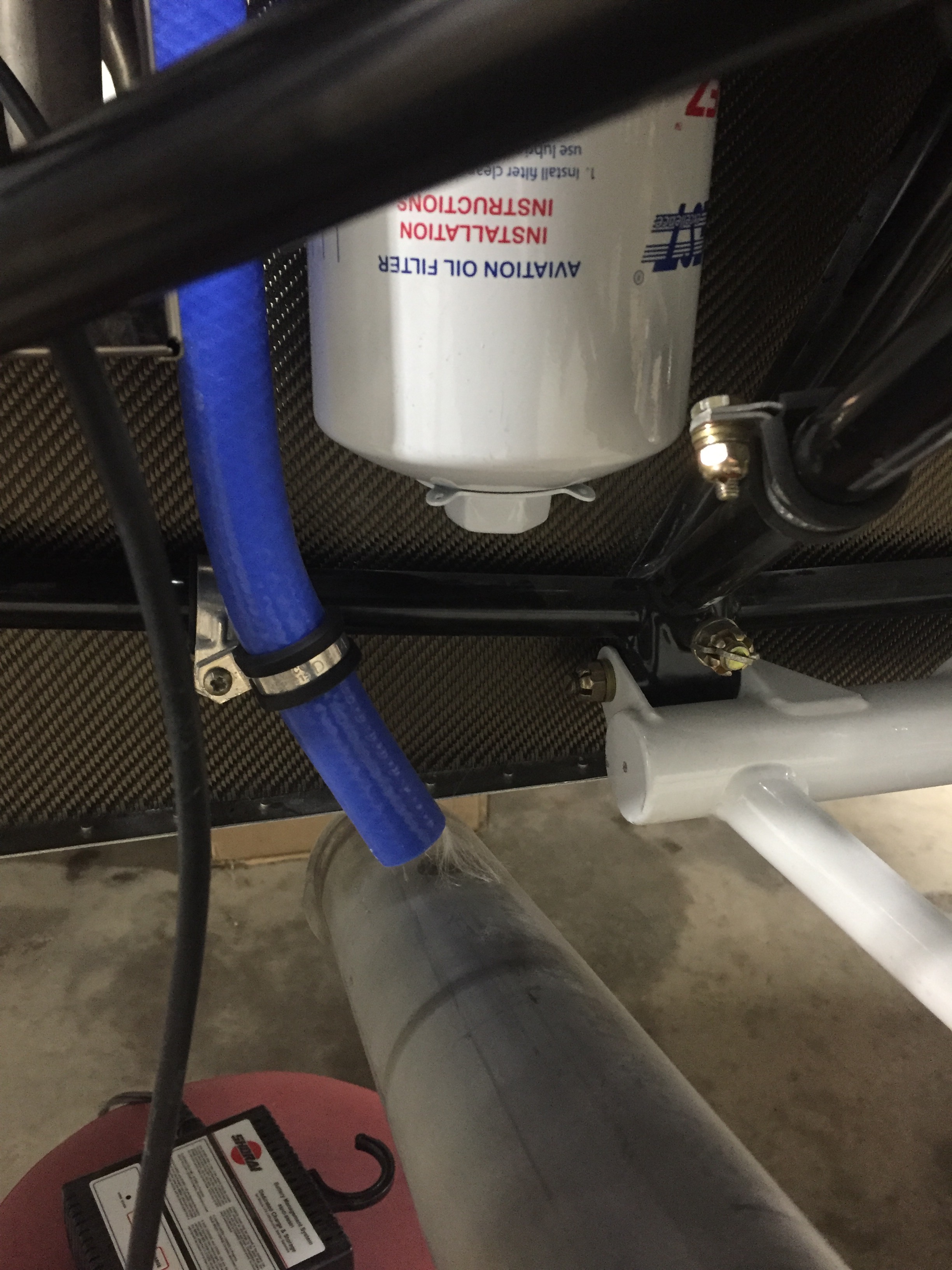
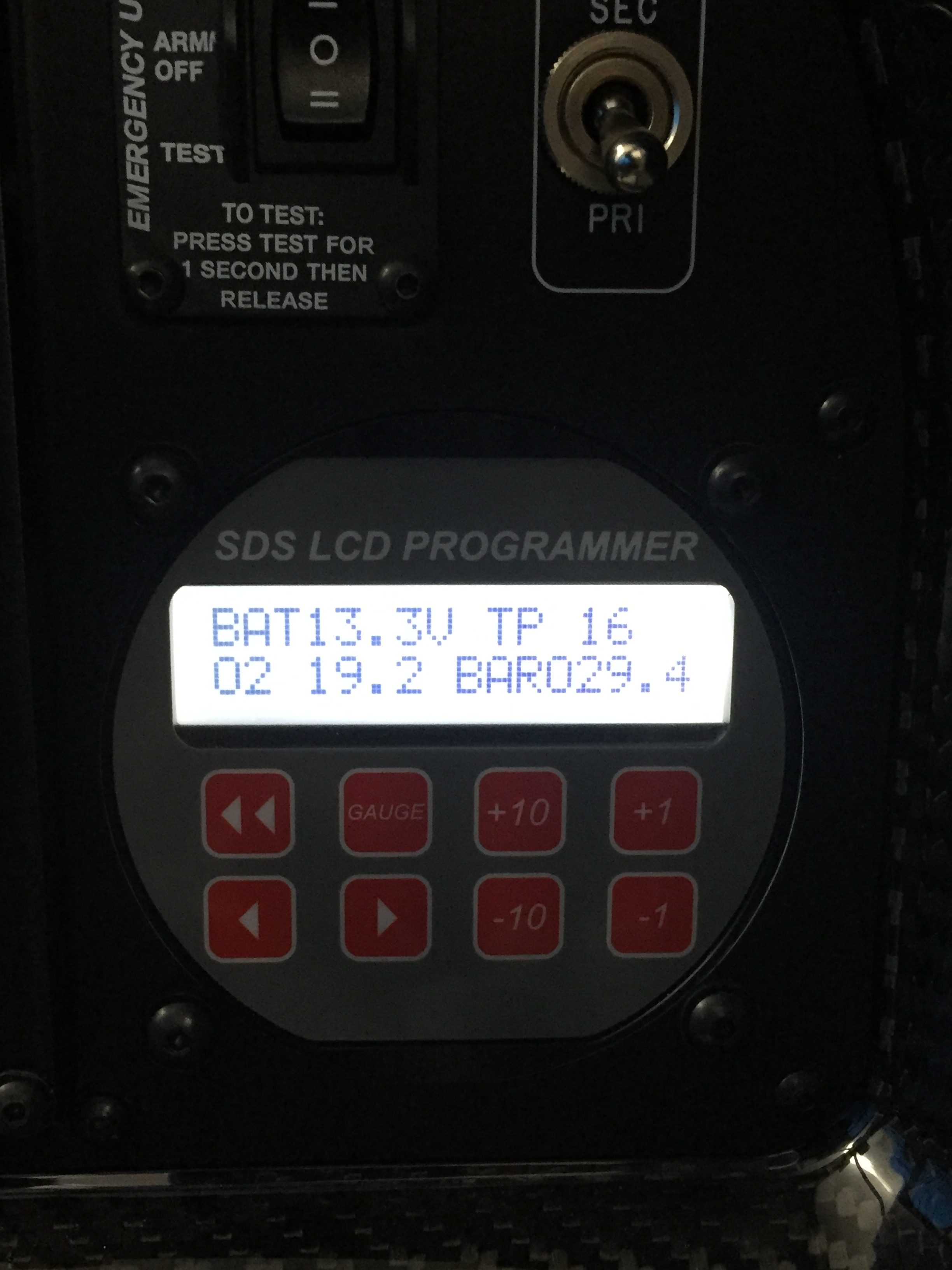
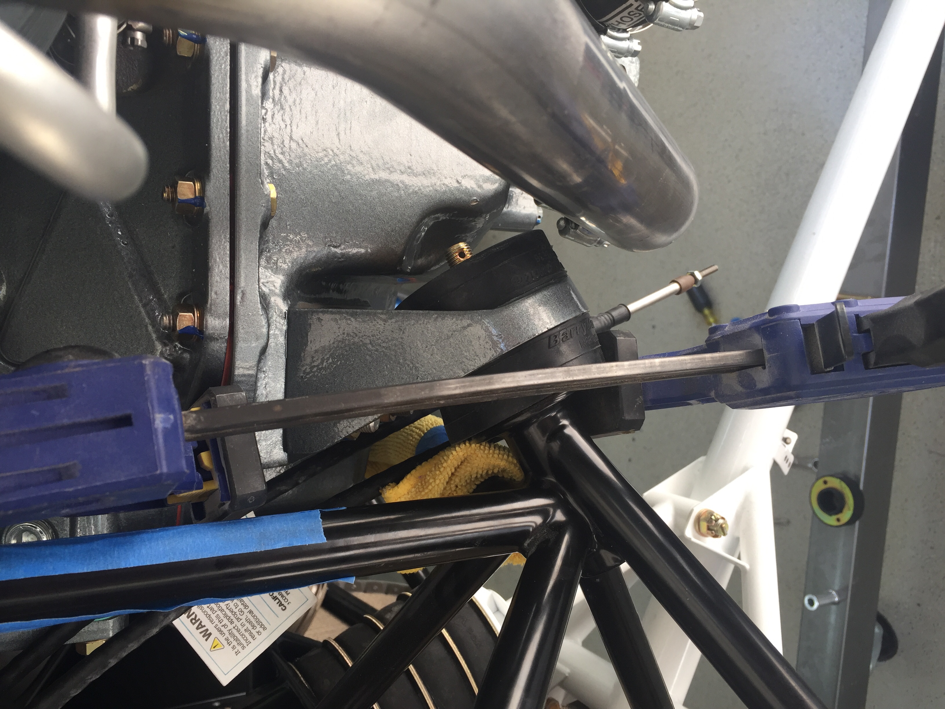
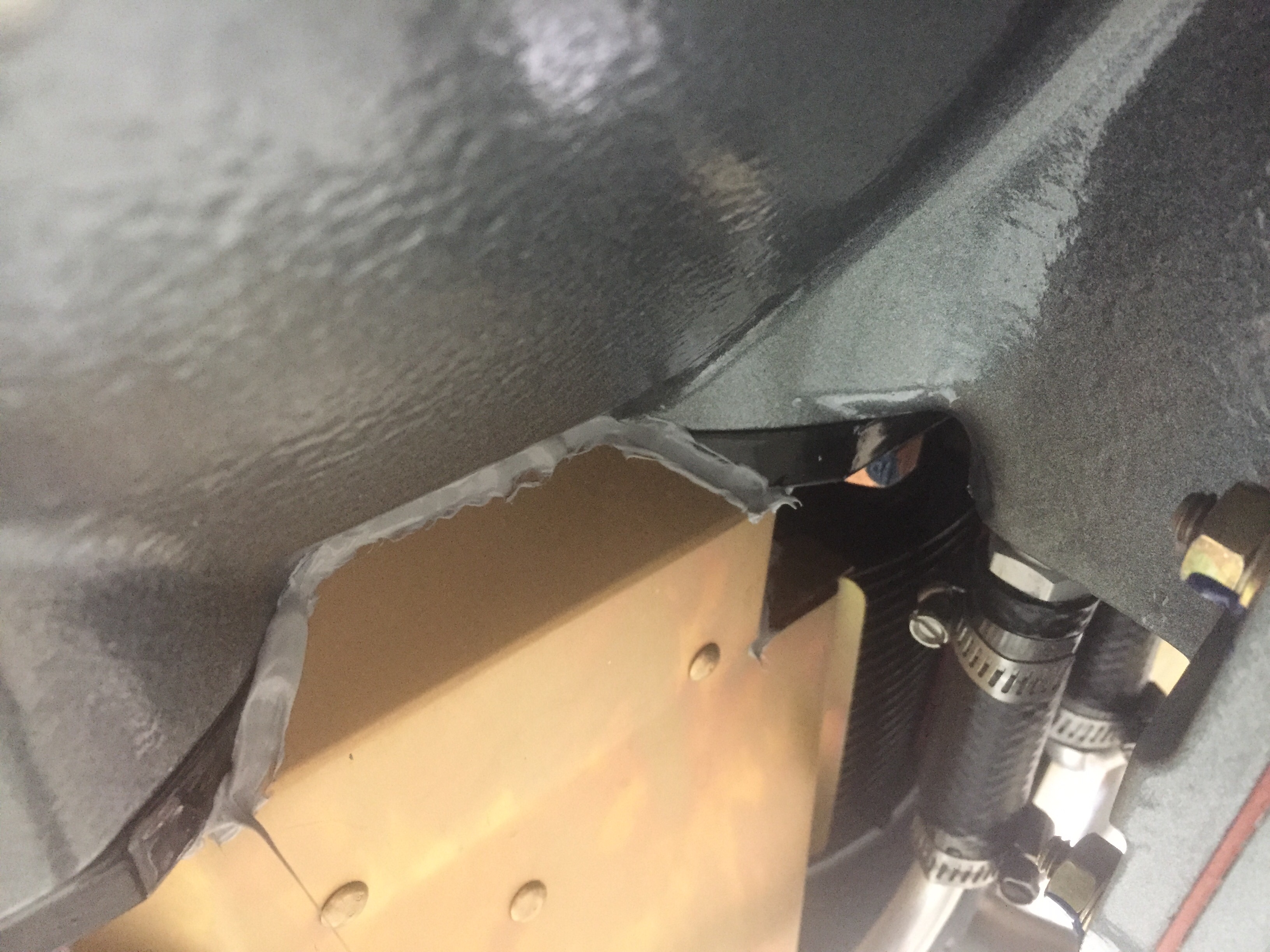
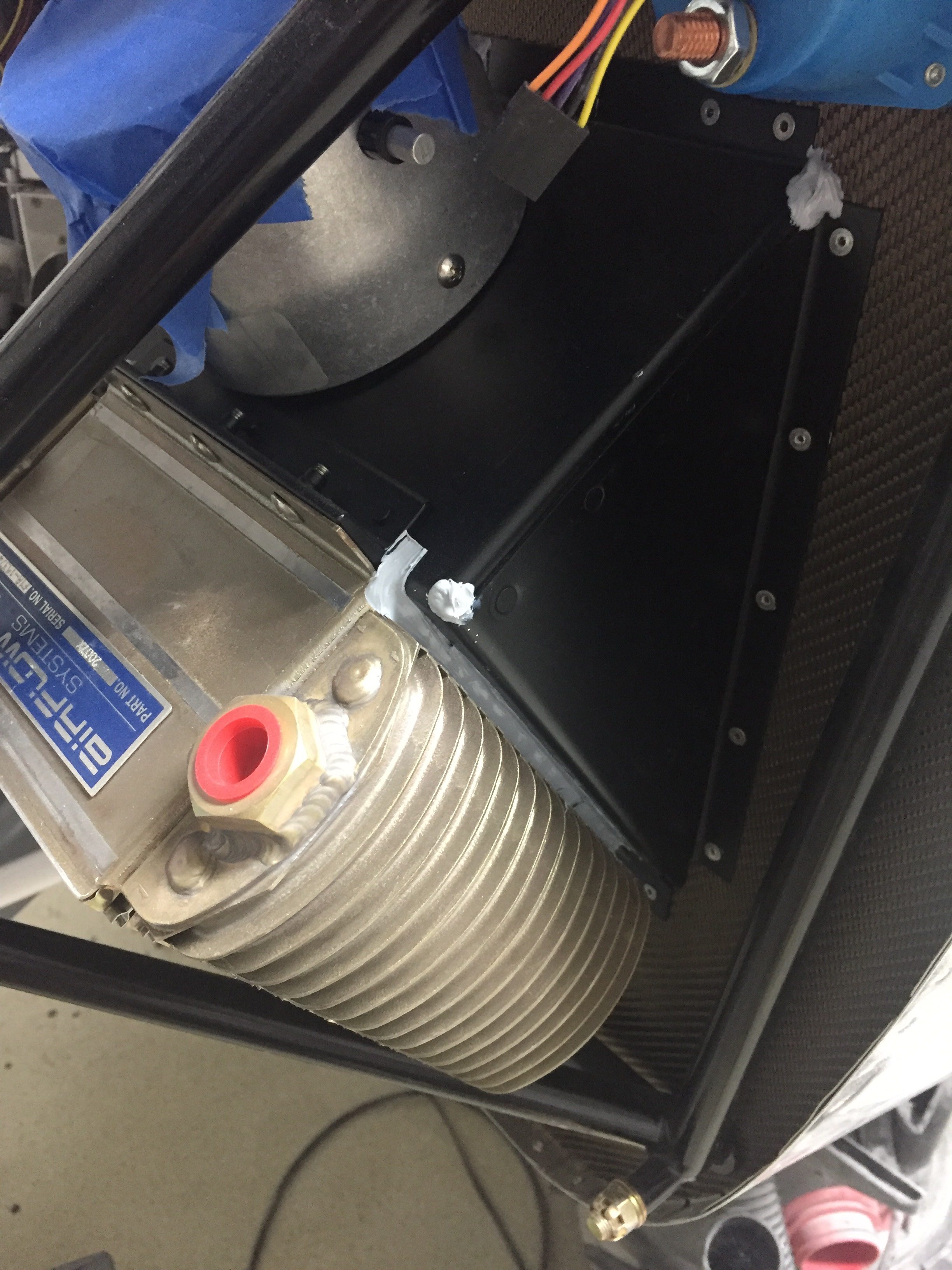
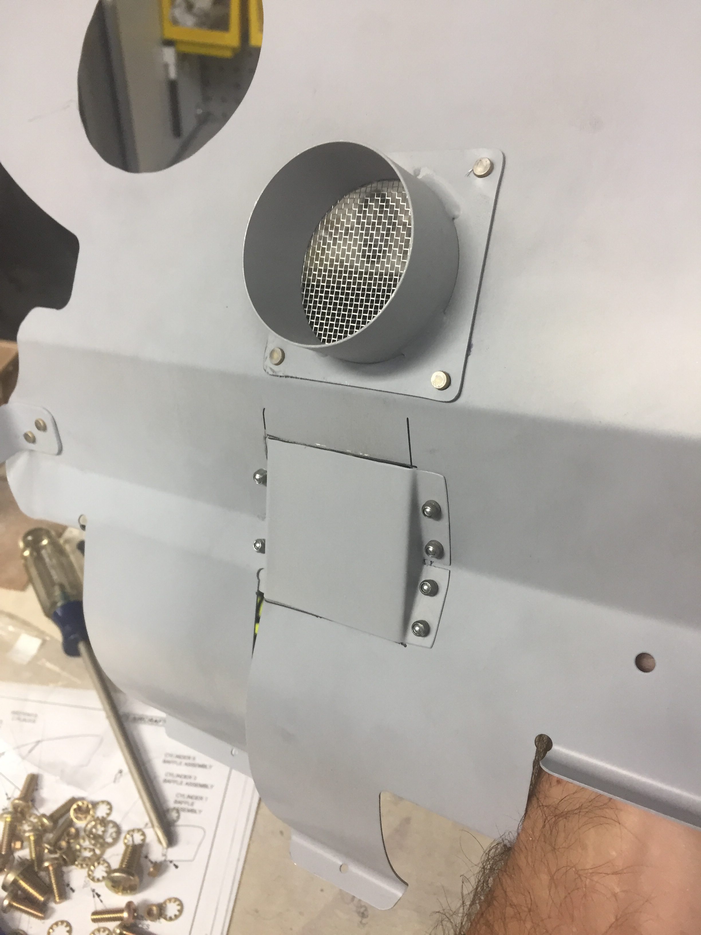
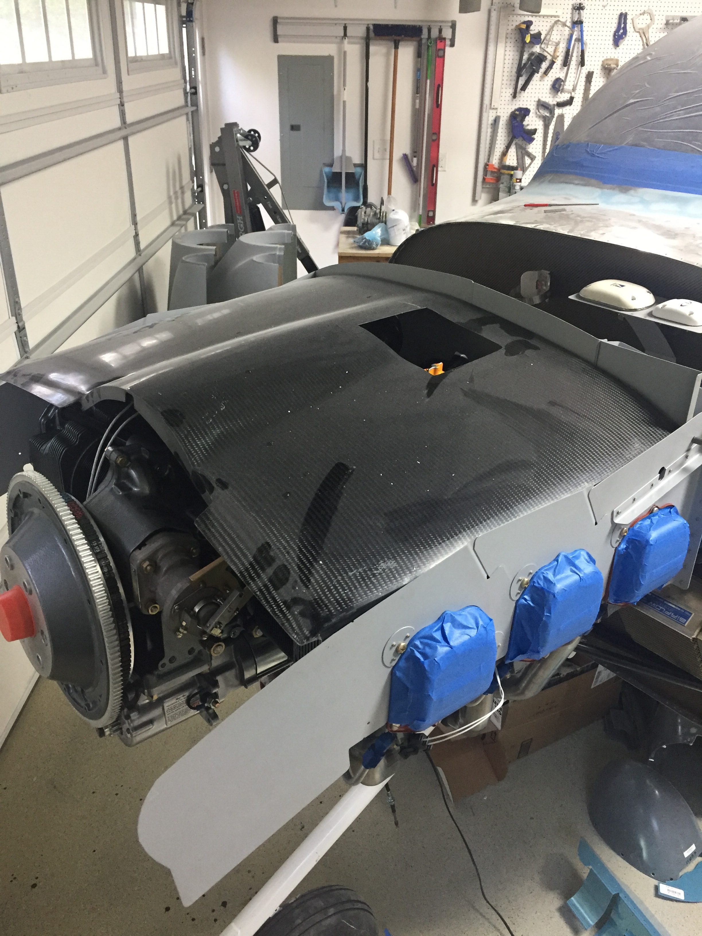
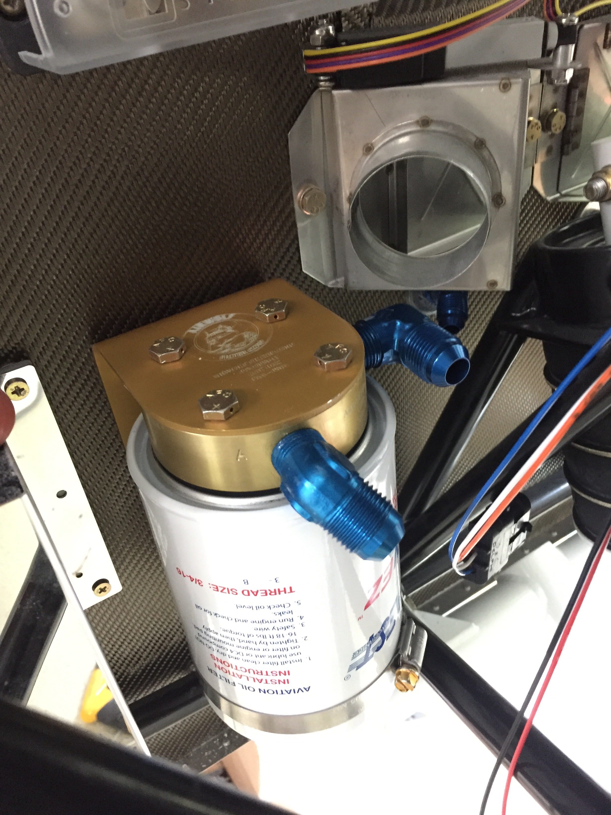
The engine ECU tweaks were pretty easy, although I’ve gone through four O2 sensors (leaded fuel doesn’t make them last long). I removed the air filters and just installed a mesh screen over the intakes. Speaking of intakes, one was too close to the exhaust header and a hole burned through it so that required a bit of glass work along with better heat insulation and a bit more clearance.

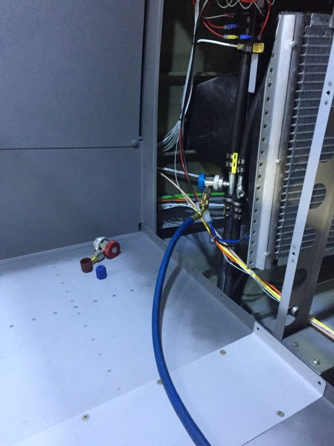
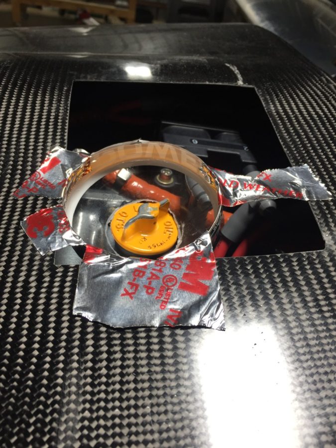
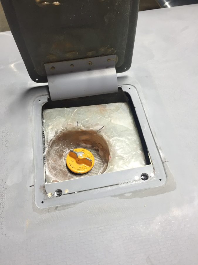
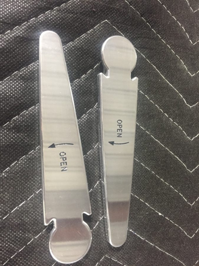
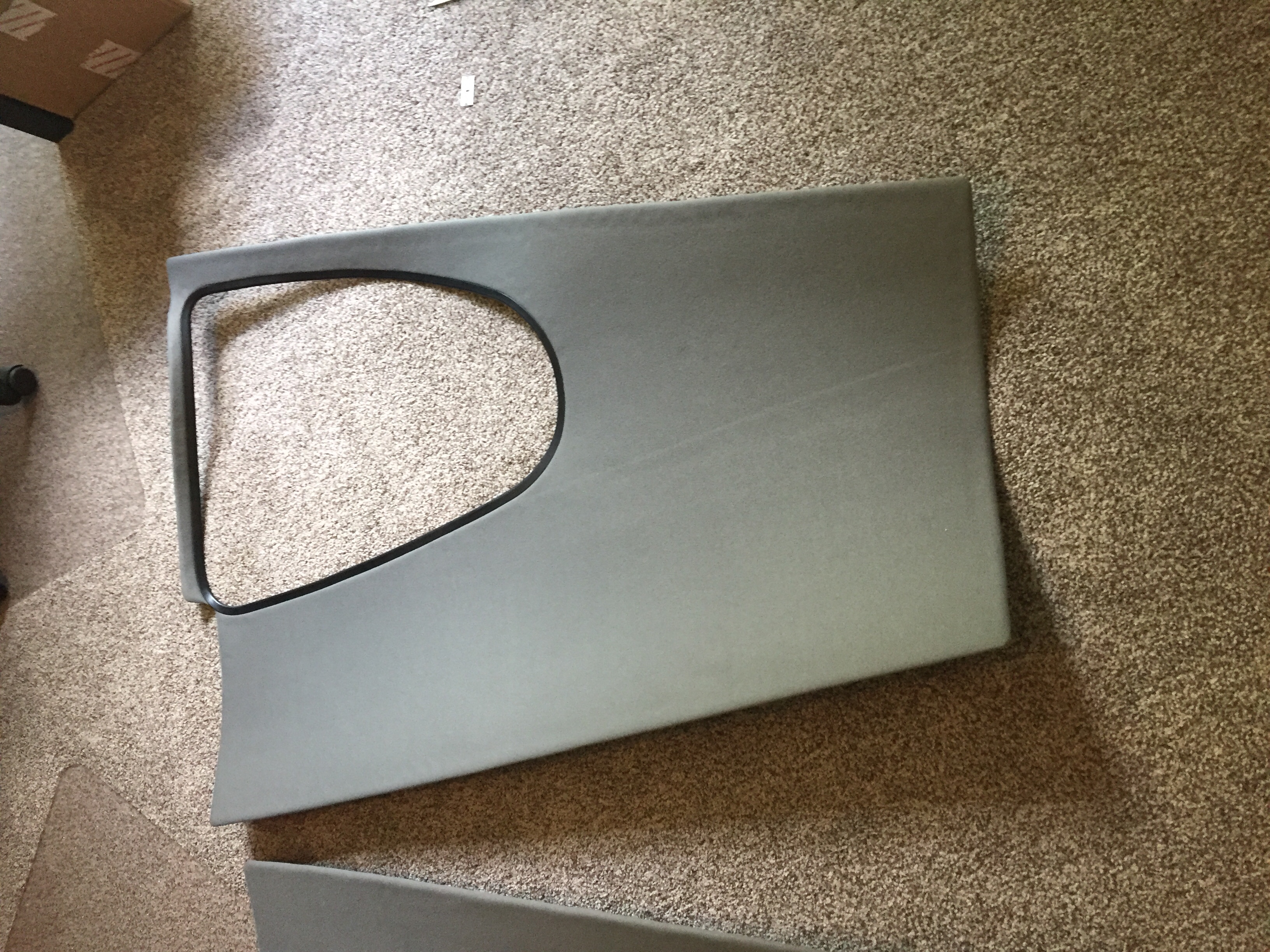
Lots of other tweaks and adjustments were made and most of these delayed discrepancies were taken care of during the first condition inspection performed in November last year. I do have a few more items to check off the list including new door hing covers, some finish rework on the interior windshield pillars, an intake plenum on the air conditioning condensor (more on that later), and adding a second tunnel access plate are all on the list for 2021.

Bottom line, you’re not done building when you’re done building. Flying brings on new stuff that you can’t forecast on the ground so it’s a continuous process to keep it in tip top shape. I also put some of this stuff off, as I wanted to get it flying so its been a challenge to get caught up after flying so much. I am now at a point where the regular maintenance time is decreasing vs the flight time increasing. The check boxes are all most all filled in!

Never ending squawk list

The airworthiness inspection is rapidly approaching and it’s crunch time now. This post is about as fast and deep as all the stuff I had to do.

The awesome guys on based helped me bend my control sticks to provide plenty of clearance to the instrument panel. I still hit the flap switch in the full nose down, right roll position, but if I ever have to use that stick input, I have way more concerns about dying.

I never installed the tips on the stabilizers, so I wiped the decade old dust off of those and riveted them on then laid up some glass to enclose them. Some tweaking with the heat gun was enough to get them adequate clearance and I’ll let Jonathan do the rest of beautifying them during paint.

I crawled in the tail cone. Again. After I said, “Oh, I’m done back there, I won’t need to get back there.” Hell, at this point I can’t even remember why I had to go back there. I’ll flash forward and tell you that still wasn’t the last time. Either way, here’s how I feel about doing that little shit job.

The rest of the interior went in and lights hooked up. These side panels are pretty tricky to slide in without destroying the paint. I’m happy with how they turned out. The stainless screws also look really nice.

I pulled the plane out for a good GPS and comm check. I’ll have another post about the details, but while everything worked, I have some serious interference with the ZipTip lights and my radios. For now, though, no night flying means I’m safe and legal to fly.

The back seats and carpet are all in now. I had to put a lot of velcro down but man, this Aerosport stuff is amazing. The seats are comfortable, the carpet looks great, and I’m really excited about taking folks flying in this plane!

My cover from Bruce’s came in and is freaking sweet. Fits very nicely, has orange, and the tail number embroidered on it makes it so no one can steal it and use it on their plane without me chasing them down.

I put the cowling on for a final fit check and hooked up the new AeroTherm engine heater. I’ve used these on the Diamond we fly and really like it. I didn’t like the idea of cylinder heaters and want to keep the engine heated during the winter to avoid cold starts. I know this isn’t as portable, but I’m happy with it thus far. I did have to get a very thick extension cord so it would keep tripping its internal breaker with my crappy 15 amp service in the hangar.

Finally, I weighed the fat little piggy with all of the pants and random stuff not yet on for good in their approximate place. Folks, with full interior, oxygen, air conditioning, three screens up front, and all the extras my credit rating could buy, I’m pretty happy with her girlish figure. This let me sit down and compute weight and CG figures as well. Everything turned out nicely with an empty CG of 106.4 inches.

Firewall forward finishing

There is a lot of little projects yet to be completed on the firewall forward section, so I set about tackling them. First off was safety wiring the prop bolts. I thought torquing them were hard. Well safety wiring them is even worse. Because of the limited space, you actually have to loosen them a bit, thread the wire through the hole, then re-torque them. Ugh. Anyway, it’s not pretty but it’s done. I’m convinced this flange design negates the need to safety wire since they’d all have to unscrew in perfect unison for the damn thing to fall off anyway.

Here is a picture of the custom wrenches I had made up using Joe Key’s templates.

Since I was at the front end, I went ahead and finished up the spinner installation. The back plate takes some time to bolt on as well with 1300 bolts used to hold it to the prop hub. The spinner has three plates behind the blades to fill the gaps and it took a bit of dry fitting to figure out where each one goes. WW had labeled them by number and I was wrongly lining them up with blade numbers not just the reference number on the spinner and back plate. The front of the prop hub fits into a bulkhead in the spinner and it took a few iterations of Teflon tape and sanding to get a nice snug fit with no wobble of the spinner.

The air filters were the last step for the intakes and I had been waiting on a different filter with a tilted base, allowing clearance of the tube to the filter assembly itself. This was required because of the blister I had to glass in for the air conditioning compressor. Fortunately a 10* tilt made just enough clearance and it all fit together nicely. I oiled the filters and got them put on for good or at least until the first annual.

The right intake tube is close to the exhaust, so I used some heat shielding that has an adhesive back to protect the tube. I went back and covered this with 3M foil tape and then applied RTV around the edges to secure it. I’ll monitor this during ground runs to ensure enough protection from the exhaust header.

Since I had RTV all over me anyway, I took the opportunity to finish seal up a few spots around the engine and firewall. I have spent a TON of time trying to find any little spot air could leak out of the baffles that it shouldn’t be leaking. Since the hangar is dark with the lights off, I again used a flashlight on top of the engine to highlight any little spots. It worked great and I’m hoping it pays off with adequate cooling once flying. It’s impossible to be super clean and fancy with this stuff, but I kept most of the mess on me instead of on the engine.

So many of my electrical connections are oddly shaped so getting a boot to fit hasn’t been easy or even possible. I used a 3M product to paint electrical tape onto the hot studs just to keep a surprise shock chance low. Not quite as good as boots, but better than nothing.

Lots of zipties up front still being added as I just see spots here or there that could use some extra security. I may add wire wrap that is rated for high heat to clean it up, but not sure if I care or want to spend the time on that quite yet.

Multi-tasking is key at this point so I setup the vacuum pump on the aircon system while RTV was setting up. All of the lines and connections are secured so I could finally vacuum the system to perform a leak test and evacuate moisture from the system. The ports are just behind the baggage bulkhead and pretty easy to get to. I set up the pump and let it run for about an hour and a half to get moisture out then closed the pump off and let the gauges sit all night long. The next day I returned to see a perfect vacuum still holding, so that is a huge win!

The last two projects up front were some additional glass work on the plenum and a ramp for the aircon compressor. The plenum was designed to be sealed to the cowl around the oil dipstick, but I didn’t like the idea of air potentially leaking out of the plenum through the oil door or into the engine area. I cut up a sports drink bottle as a mold and roughed up a little funnel to fit over the dipstick. The dipstick will have some foam tape sealing the bottom of the funnel. It didn’t come out as pretty as I wanted, but it’s functional and I can always clean that up a little down the road.

The air ramp was a little easier than I expected. On the left side intake, the aircon compressor causes the cooling ramp and induction intake to need a cutout and I wanted to create a little blister to help direct all the air possible into the cooling and intake ducts. I shaped a foam block and used packing tape to secure it to the cowl. I used some carbon fiber to lay up a rough fairing then cleaned up the edges after it set up. This is attached via two screws and should provide a nice air flow deflection that is simple to use. I plan to create a final piece of bulb seal to fully seal the cowl to the engine portion helping minimize air pressure loss while providing flexibility for engine movement.

Throwing gas on a fire

I’m getting bad at taking progress photos, as quite honestly I’m under the gun on getting this thing airworthy and ready for inspection by November 12th.  So I’m really powering through a lot of tasks and am so exhausted by the end of the night I just forget to document it all.

We got the wings back on and permanently bolted on.  I had to order a few washers as the nuts bottomed out on the threaded portion before they should have.  I just added one washer on each bolt and got the proper torque value with no spinning in the hole.  I did the same with the main landing gear bolts on advice from another builder who had a bugger of a time replacing the bolts after the holes elongated.

Fuel testing is next on the list and a big hurdle to climb over.  We had pressure tested the tanks, but I was still a bit nervous to put avgas in them for the first time.  I collected all the gas cans I could muster and had enough to hold 36 gallons for the first fuel tank test.  I also bough two two-gallon cans to calibrate the fuel senders.  This test is not only for the tanks, it will see if I have leaks in the lines and will finally show what fuel flow the pumps provide, a key test point for first engine start and flight.

We started by filling the left tank at two gallon intervals and capturing the value on the avionics to create the level points.  The cans nor the amount in them were exactly precise, but it was close enough.  Parish and Jacquie came over and helped us with the reward of eating pizza on the ramp after filling the tanks.

We did 30 gallons in the left and then removed the sump drain to empty the tank and prepare for calibrating the right tank.  The right went pretty easy and we had no leaks on either tank!  I was nervous about leaks but the tanks held great.  Parish and I worked out a good technique of draining the fuel and switching gas cans.  Much easier with two people!

After the right tank was calibrated, I removed the return line from the firewall and put in an empty can to get ready for the flow and pressure test.  It took a few long seconds for the pump to purge air and draw fuel, but after what seemed like eternity, the noise changed and the pump got a hold of liquid.  Unfortunately, that liquid came spewing out of the firewall instead of the hose!  Turns out I mixed the fuel supply line and return line on the tunnel side of the firewall.  That caused a big oh shit moment!

A bit of head scratching and cussing lead to digging in the already disassembled tunnel even more to get at the firewall.  Folks, not an easy task.  Two extensions, crowsfoot, and a lot of scratches, but I was able to get the lines un-crossed and hooked up on the tunnel side correctly.  

We flipped the fuel pump on again and had fuel coming out of the correct line.  We also had fuel coming out of the filter fittings.  Yup.  So, back in the tunnel I go.  Like an idiot, I didn’t use fuel lube (EZ Turn) on the AN NPT fittings into the fuel pumps.  I did for the fuel pumps manifold, but not the filters.  Gah, idiot.  So I had to take the whole fuel pump/filter module out and get at it on the bench.  While it’s not impossible, it’s not easy.  I’m definitely putting another tunnel access panel on the copilot’s side during the first annual.

Fittings were properly lubed and torqued, so the module went back in and we turned the pump on for a third try.  That was the ticket, as we got good pressure readings and good flow.  I turned the pressure up a bit to 45 PSI on the regulator and we did flow tests equaling 45 GPH on a single pump and 75 GPH with both on.  Plenty of fuel to feed the thirsty engine on take off!

Tess had one more surprise for me, though, when I attached the return line back to the firewall and found one more leak, this time at the outlet of the pressure regulator.  Seems that I didn’t torque that line at all.  Oops.  Again, this is why you extensively ground test!  Got that one all fixed and ran the pumps for about 30 minutes, just recirculating fuel with no issues.  She’s ready for engine start!

Back to my roots

The wings are initially fitted to get the wing root covers installed and hook up fuel lines, vent lines, while getting the flight controls initially rigged.  The wing root cover brackets went on quickly and I fabricated the two fuel vent lines that exit the bottom of the wing root cover.

You also drill the bolt hole in the rear spar and work out a few other fasteners.  I installed the flight controls and worked out the stick to the plans while adjusting the rigging and pushrods.  It wasn’t too bad of a process with a little patience and double thinking before adjusting a rod end the wrong way!  In an afternoon, I had all the controls lined up nicely with the wingtips and fuselage just as described in the plans.

I also finished up the fluid lines up front.  TS Flightlines really came through again on an awesome product.  I had one line that didn’t quite fit to standards and the return lines for the fuel tanks from the tunnel had the wrong fitting (my fault) on them, so those went back for modification.  If you don’t know, TS will rebuild the lines for free until they are correct.  You get what you pay for and I’m glad I spent the money knowing I’ll have lifetime quality hoses.

On a side note, my engraved parts came back looking fan freaking tastic.  The door handles are an extra set that I had and will go on after paint.  The data plate turned out perfect, as did the fuel caps..

Speaking of fuel, a while back I misdrilled the holes in the tunnel on the right side for the fuel line.  I decided at that time to just use a 90* elbow but that made torquing and replacing the incorrect fuel line difficult to say the least.  So I broke down and ordered 90* bulkhead fittings to do it correctly.  I had to dig into the tunnel to put the proper spacers (covering up the now too large hole) and secure the lines from the fitting to the fuel valve.  Boy am I glad I did this, because while looking around since I was in there, I discovered a cross threaded line on the fuel valve that would have made a mess come testing time.  I was able to clean the threads on the fitting and got it on correctly.  I took my time to reinspect all other fittings and lines.

With the airworthiness inspection scheduled for early November, I am shifting into inspection mode so try to check everything I can while working in an area.  It just so happens that the 137 articles Vic Syracuse has written for KitPlanes all mention loose jam nuts!  I want to break that chain but came close to being a statistic in your next bathroom reading material.  The left aileron jam nut had just enough space that it caught my eye while working the fuel lines.  Ha!  Not today, Vic, not today!

Another little side job that had been lingering was wrapping the aircon line with insulated tape to ensure the thermostat coil was in good contact with the line.  I had ordered this sticky tape months ago and finally crawled into the baggage area to finish that up.

Finally, Laura came over to help me pull the wings off so we could prep and install the wing root brackets and finish up the few tasks before permanent install.  This coming weekend will be critical for staying on track towards inspection, as I need to get the entire tail surface wrapped up and the fairings done.  Fingers crossed!

I give you wings, Red Bull gives you diabetes

Before the wings go on, I finished up a few odd jobs since the parts came in from various suppliers.  I ordered enough hose to route from the air oil separator to the cowl exit and secured it in place.

I also finished securing the air con hoses from the firewall to the compressor.  I made a bracket to hold hose clamps on the bottom of the valve cover and it keeps the hoses from flopping around the side of the engine.

I also did something on the right side of the engine.  I don’t know what I did, but I took this picture which meant I did something over there.  I know I secured a few wires, added a ground from the engine to the mount (which I may have mentioned before, I don’t know), or maybe I just felt it looked pretty.  Either way, here’s the right side of the engine and the mass of wires; enjoy.

Tapping into my network of gulible aviators, I ropped two guys into helping me install the wings for the initial fit.  I must admit, I typically don’t read ahead more than a few steps in the plans so I was pretty dissapointed to find out the wings go on then have to come back off before getting bolted on for good.  It figures, though, you wind up doing everything twice on this airplane so why would the wings be any different?  We got a few sawhorses and a plan together and according to the time lapse video shown below, we installed the wings in about 27 seconds!

Really, they went on a lot easier and smoother than I expected.  I ordered new nuts for the wing attach bolts but will reuse the original bolts used during construction of the fuselage.  I did get the suggested hardware store bolts to align the wings initially and they worked very well.  I also felt better seeing the good fit between spar components, as I had a scary moment a few years ago when I realized my spacers weren’t the proper combination even though the dimensions worked out in the end.  Either way, everything fit snug and as it should, so all is good.  Great job Steve, smile for the camera.  Or not.

It’s pretty bad ass to see wings on the plane after 6 years of telling everyone you’re building a plane but it actually looks like an enclosed canoe.  So I decided to have a bit of fun and hook up the ZipTip lights.  Combined with the gull door lights, it looks like a space ship!

The evening was getting late, but the big triangle box was too tempting for me so I pressed on with hanging the prop.  Following the manual, I inspected and oiled the critical o-ring on the hub and ensured no damage as it slid on the prop flange.  Again the engine hoist came in handy as I secured the prop to the hoist and used it to lift in place without asking for a third back surgery.

The bolts for the propeller are rediculously stupid and hard to get to.  Once I got each one threaded, a challenge in itself, they can each be turned about one revolution at a time before all the others have to be tightened in sequence.  There just isn’t much room and you want the prop to go on evenly.  An hour later, I had the bolts hand tight and the prop was on.

I realized quickly by my goose bumps and those on the propeller blades that it was chilly, so I went and got some socks for her.  David makes these as a business (search BladeSox on Facebook) and they are just the bee’s knees.  I don’t care if they make me a super dork.  I had him do the tail number, Van’s new logo, and the best – our RV10 logo created by Sam at Plane Schemers.

It’s really starting to look like a plane now!

Brains and speghetti

Hanging the engine seemed like a big step, but wiring it and plumbing it is the real work.  I knew the connections to the ECUs and sensors would be a big job, but I thought the days of electrical wiring were mostly over.  Boy was I wrong!

I brought it on myself, really, as I knew using SDS would be deep in a mess of wires resembling an Olive Garden menu.  It’s absolutely worth it though, as I’ll wind up with a powerful and efficient (relatively speaking) engine with lots of tuning ability and choice of running LOP with a simple flip of a switch.

I started by screwing the ECU relay box to the ECU case itself with a few screws tapped into the ECU case.  This creates a tidy package that will bolt into the cabin side behind the subpanel.  I also put the mixture knob relay box on with double sided tape to secure everything in one palce.  I had already mounted rails with nutplates in the subpanel.

SDS supplies a harness with labeled wires and prefabed Dsub connectors.  I fished all the wires that will go firewall forward through the stainless penetration and quickly realized there was no where near enough room to run all the wires.  I still had the CHT/EGT and other EMS wires that needed to come through for the AFS EMS plus a few other misc wires.  Without regards to symmetry, I decided to scrap more of the expensive firesleeve penetration kits and just run with a silicone high temp grommet and fire stop.  The plans call for a plastic grommet and fire stop, so I’m still above minimums here.  Two more holes painfully drilled and deburred in stainless steel allowed enough room for the tangled mess.

I underestimated the amount of connections and sensors needed for everything!  It seemed the wires never stopped and I always had more hanging waiting for their turn in the spot light for a trim and terminal.  Injectors, coils, EGT, CHT, hall sensor, TPS, MAP, AFR, oil pressure, fuel pressure, original bell telephone…okay not the telephone.  I routed everything as neatly as I could keeping in mind strain releif, heat sources, and interference from other wires.  I’m sure someone could do it better or neater, but this is working for me and I’m not really trying to win a neatness contest at this point.  I chose to use zipties for now and will experiment with a 500*F rated sprial loom from McMaster Carr to clean everything up a bit down the road.

I focused on the firewall forward and finally had everything connected and pinned out.  I created a carbon fiber plate for the THREE MAP sensors, yes, three of them.  I also used Bryan at Show Planes’ transducer mounts to avoid more stuff on the firewal and create less plumbing lines.  I also worked on the spark plug wires which use MSD terminals and wires.  They were pretty easy to make up and I went ahead and drained the preservative oil out of the cylinders to install the spark plugs with the adapters and anti-seize.

I did run across my first dumb ass moment when I relized my perfectly placed EGT probes are not perfectly placed.  They are smack dab in the middle of the spark plugs and thus need to be removed to change the plugs.  Not the end of the world, but will add maintenance time down the road.  If I get tired enough of them, I’ll remove the exhaust, weld up the holes and reposition them.  Speaking of welding, I had Charlie on base weld up a mis-drilled EGT hole (interfered with the induction intake) and the AFR bung.  As always, he did an amazing job for the reasonable cost of a few cases of beer for the shop.

Fast forward a week or two, I finished the brains by working cabin side of the firewall underneath the panel.  I just love contorting my body in some ungodly yoga pose upside down while having my face inches away from my work area to work under the panel!  Fortunately, the wife came out and stood by my side as an assistant for the three hours it took me to terminate all of the extra wires inside.  I had to pin out a few switches, mixture knob, sensors, grounds, power, and signal wires for the ECUs and EMS.  It wasn’t fun, but it went well and I got all of the connections made correctly with her help and a lot of triple checking.

We also remounted the air oil separator on stand offs I created and bolted the improperly drilled holes to seal the firewall.  Mounting the ECUs was a rediculously difficult endeavor but thank goodness I had already installed the rails and nutplates.  Without those, it would have been impossible, truely.  I hope I don’t have to get those boxes out very much if ever at all.  The wiring needs some tidying up underneath that I’ll do another day but at long last, it’s all hooked up.  The final step was to fire up the master switch and check out the ECU programmer now that it is installed in the panel filling the last hole.  It’s at long last a complete instrument panel!

Hate to say it, but you’ve gained weight

About 375 pounds to be exact, all on your front end!

I enlisted the help of friend/flier/builder/neighbor Dan Olsen to help me hang this piece of art on the front end.  I had done a little prep work such as sealing a few penetrations in the firewall that would be tough to get to and removed the air oil separator, as I was pretty sure my original location would interfere with the back up alternator.

Some folks have had a lot of headache while hanging the engine while others have thrown it right on.  Overall, I’d say we were towards the later, as the engine behaved admirably and didn’t give us too much trouble.  We supported the tail of the fuselage to put the nose gear on the ground and used ratchet straps on the engine hoist so we could adjust the angle of the engine relative to the engine mount.

The top mounts went on easy, of course, and we secured the hardware enough to hold it in place.  The lower bolts were the more difficult ones, as with the dynafocal mount, the engine needs to be nested in the mount but gravity is working against you.  We found that using a easy grip clamp helped hold and compress the mounting pads enough that the bolts were able to be tapped in without much force.  It all sounds simple and easy but was 30 minutes of tough work and a lot of maneuvering tools.

Four bolts in and we have an engine!  Remarkable that all of the force, torque, and stress is secured with four bolts.  The mount modification by Barret was perfect for the cold air induction and it’s nice to have the fuselage balanced nose heavy now so no more tail stand required!  She is officially a tricycle aircraft now, not a four wheeler.

I took some extra time and used my sealant gun to really seal up the factory intercylinder baffles well.  I’ve researched and discovered this is critical to keeping cooling air traveling through the intended paths and fins which helps control CHTs in flight.  Doing it now before accessories and exhaust are mounted makes the task doable and the sealant gun with curved nozzles makes it easy.  It was actually really fun finding all the little spots to seal up and visualize where are can escape from the cooling envelope.  It also makes a lot of sense how you can not get great cooling from a stock engine and baffle setup without some extra TLC such as this.

The oil cooler was also installed and sealed carefully to maximize air efficiency through the cooler.  This is the next size up from the stock cooler and the modified mount works great without a lot of fuss.  I’m sure it could be better if I had mounted it paralell to the ground and had a nice clean duct, but folks are flying a lot with great results just as I am doing it.  The butterfly valve should help keep the oil temps higher in cold/high altitude flights that we have planned.

Baffles are up next and can be a bit of a tricky project to get completed.  There is also a well documented modification on number 6 cylinder that I’ll do to increase cooling and help reduce CHTs on that notoriously hot cylinder.  The baffle on number 5 is the hardest to fit onto the engine, so I taped up about everything to avoid or at least minimizing messing up the goregous paint job on the engine.  There are a lot of unique pieces of metal and I am awed at who ever designed the presses to stamp these things out.

Behind number 6, the fins are not deep enough to allow air to channel between the cylinder wall and the baffle.  Some have put a washer here which just pushed the baffle out a bit and allows some air to go through.  The RV-14 has a new mod where a channel is built in which provides clearance in that area, so I made the same modification to mine.  A few mockups using manilla folders, and I finalized a design which I riveted on and will seal once painted.

Once all the stock baffles are on, it was time to fit my RV Bits carbon fiber plenum.  I had this shipped all the way from South Africa and it’s a nice piece.  If someone wanted to create their own, it really wouldn’t be hard but it would take some time.  I positioned it to maximize the opening up front around the intakes but keep it clear of the cowl which should help keep the pressure higher on the cooling side.  That increases (in theory) the delta P between the high and low side of the engine as the hot air passing through the engine is sucked out the bottom of the cowl exit.  I initially drilled holes in the baffles and plenum but later redrilled the baffles after fitting the cowl (to be documented in a future post).

The Airwolf remote oil filter has a spot reserved low on the firewall near the battery box and wound up being perfectly placed.  I installed the brackets and doubler along with the fittings and tested the filter out.  The lines run up to an adapter that mounts on the accessory case and includes the vernatherm and oil temp sender.  This and a quick drain oil plug should make changing the oil a no-mess event.

Splash of color and an Oops

After returning from our trip up north, only a few days passed until we received a big package with a piece of art inside.  Our (second) propeller has arrived!  Whirl Wind delivered about a week late, but with prior coordination and communication with me so I was super excited to see what it looked like.  As chronicled earlier in the build, I purchased a propeller but decided to sell it instead of it hanging on the wall for three years before I was ready for it.  Joe Keys, you can’t have this one.  I knew I wanted another WW and the HRT blade is now a refined blade profile and is simply stunning.  Our orange was color matched and looks great with the black and nickel leading edge.  For now, the prop will go to a friend’s hangar to hang out with the wings until we move to the airport.

Adding even more color, I finished up the last of the wire bundling on the cabin sidewalls and went ahead installing the side panels with leather inserts.  They had been trimmed and painted for some time but I held off pulling them in and out until I knew I was done.  I spoke to Vic Syracuse who will be my DAR for airworthiness inspection prior to putting these in, as I wasn’t sure how open he wanted the airplane.  He advised to have it essentially flight ready except for rear pax tunnel cover (to inspect the elevator bell crank), cowling, and tunnel access panel.  This is the first time I’ve hooked up the foot well lights and I’m really pleased with the amount of light they give off.  It’s just enough for convenience while not quite enough to perform surgery on the floorboard.

Unfortunately, not all of the gods were looking favorably upon this new addition and when I closed the door, the pins interfered with the oxygen ports, thus not allowing the doors to latch properly.  Turns out I have the ports ½” too close to the door frame.  Darn.  Well, I said, a lot more than that and maybe one or tools took flight across the garage with no lasting damage.  My blood pressure through the roof due to my ignorance and stupidity of not being mindful to this interference, I weighed the options of replacing $500 panels or coming up with a patch.  I can’t make the pins shorter since they wouldn’t function correctly with the Plane Around latch mechanism.  I had already had to glue a piece on the pilot side panel and reinforce it with a bit of epoxy.  The seam was easily hidden and paint covered everything, so I was hopeful I could repeat the process.  A call to Will at Aerosport Products equaled a few scrap pieces of plastic heading my way.  An evening of creating two patches and a bit of filler, and I’m back on track.  If you look close enough to tell the patch is there, you probably won’t be flying in my airplane again; kindly go away and take your judgement with you.

Meanwhile, I applied the 3M carbon vinyl wrap on the seat pans to clean those up.  I figured out quickly paint was not going to hold up there.  Brian and Brandi had great results with the wrap material, so I figured it’s worth a shot.  I then put a strip of anti-skid tape to facilitate stepping on the seat ledge while getting in and out.  It really cleaned up the area nicely.  I also shimmed the outboard pilot seat rail, as the bracket above the gear mount was a 1/8” proud causing the rail to bend when screwed in.  Not sure what happened there, but with a few washers underneath it’s nice and straight and secure.

I quit trying to cheat the system and installed the ELT antenna on the top of the tail cone.  I tried every which way to hid that hideous monstrosity of an antenna but my conscious told me that it is probably the most important antenna on the airplane thus deserved its place per the install manual.  I’m sure it will grow on me.  The idea of burying it in the tail cone or tail fairing was tempting, but a talk with my DAR convinced me otherwise.

Continuing in the cabin, I spent an afternoon applying the headliner material to the fiberglass shells from Aerosport that had been trimmed for quite a while now.  It was a bit of a messy job with the spray adhesive, but not difficult at all.  I took my time and kept my fingers clean which resulted in a darn near perfect result.  After putting enough Velcro to hold a car upside down, the headliners slid into place and really dress up the cabin cover now.  The color matches great and was overall a lot easier than trying to smooth and paint the cabin top itself.

Finally, the rear bulkhead cover was back from Aerosport with the matching leather and embroidery.  I used Velcro to mount it to the bulkhead panel after installing a grill for the air conditioning return.  It turned out great and I’m really pleased with the fit and finish once it was all installed.  The cabin is really coming together with the rest of the rear side panels installed and inserts in place.  It’s tempting to put the carpet and seats in, but I’m holding off to keep them in good shape and clean while I finish building.

Upfront, I had an epiphany about my shotky diode and how it should be used to protect my engine bus.  The goal was to isolate the engine bus from the rest of the system such that I can turn the emergency power switch on (direct connection from battery to engine bus) and not have the electrons go to the man bus.  This essentially covers a short somewhere in the system or electrical fire behind the panel and gives me a bit of redundancy on keeping the electrically dependent engine going.  I wasn’t placing it on the proper power lead on the schematic, so it finally dawned on me it should go from the main power supply instead of the backup lead.  So, I installed it on the firewall and will work on a solid copper bar to hook everything up.

Punching the punch list

There are a lot of little jobs that go along with the big jobs on building a plane.  I’m trying to use my time efficiently while waiting on the engine to knock out a bunch of them.  The first was fixing the arms and servos on the heat ducts up front.  An order to ACS and a few minutes at the band saw and the servos for the heat and oil coolers were attached properly and pots adjusted for full travel.  I also spent an hour trouble shooting a bad pot for the rear heat duct, as I have a switch that allows either the front or rear rheostats to control the servo and the rear rheostat was inop.

I cussed and bled in equal amounts installing the last of the seat rail brackets now the gears are on.  The nuts and bolts are not easy to access at this point, but you have to wait in order to install the gear bolt.  I also put in the last bolt and custom spacer for the GPU plug which helps reinforce the receptacle by attaching it to the seat pan.

I ignorantly forgot to install the transponder antenna before buttoning up the tunnel, so I had to take the center console, tunnel cover, and lower instrument panel off to get down in there.  Of course I burried it near the core of the earth which made access tricky to say the least.  I was able to squeez my hands down there and got it all bolted on with the coax attached.  I knew I had left one fuel line untorqued but couldn’t remember which one so checked all fuel line fittings for proper torque.

The last task in the rear tunnel is to secure the aircon lines which I did with some hose clamps and edge grommet material.  Again, not fun to get to the hardware but it was doable and will rarely if ever be removed.  The lines are now secure and fit nicely in the tunnel, I’m glad I didn’t run them down the side of the fuse.  I also secured the last little sections of the O2 lines in the tunnel.

My ELT antenna placement has been a topic of disagreement on VAF, as I really wanted to avoid mounting it on top of the tail cone.  It’s big, ugly, and ugly.  Mainly, though, it’s ugly.  It’s also essential to my life and the lives of my passengers should the worst happen and we have an accident, so I guess it’s important to do it right.  I debated on doing some reception tests with it mounted internal to the tail cone, but honestly, I just got lazy and decided it really isn’t that ugly.  In the end, I chose to do it the right way and put it on the top of the tail cone.  The cable was secured along a bulkhead and the last of the wiring clean up for the O2 tank / ELT was completed.

I love spending time wiggling back into the tail coffin, I mean cone, so I made a fort with blankets and towels and dove in to attach the OAT sensors to the ADAHRS and finish securing tail cone wiring.  I put the OAT sensors below the access panels underneath the horizontal stab since I had all of my wing wiring complete and for shorter wire runs to the ADAHRS.  Since they have to be calibrated anyway, I’m not too concerned with exhaust from the engine affecting them too much.

The O2 tank was put back in for good and connected to all of the lines.  I also attached the pitch auto pilot servo to the bellcrank and will connect the yaw servo once the tail feathers and rudder cables are rigged at the hangar.  That is the last task in the tail cone and can be completed without having to crawl all the way back there.  It’s going to be motivation in life to keep from getting fat or have a small child that can slide back there for maintenance, it’s a very tight fit with all the extra stuff I put back there.

More zip tie work on the side walls as I cleaned up all of the wire bundles.  I was lazy and didn’t lace them.  If you don’t like that, you go build your own damn airplane!  Lots of zip ties.  Overall I’m happy with the wire runs, I was able to keep coax with mainly data / signal wires and have the high current ones seperated.  I have seen plenty of aircraft with everything bundled together without issues, so I think it’s more important to terminate and ground properly than anything.

The pitot / AoA tubing needs to run across the fuselage from the left wing to the right sidewall, so I put two holes in the tunnel and used free holes from the fuel line anchors to run the blue and green tubing.  The wing is already plumbed, so these lines will connect with those from the wing with two connectors and be done.

Finally, I put the 30 amp Schottky diode on the firewall between the shunt and engine fuse block.  I had this in my electrical design but just in the wrong location.  It provides redundant power input to the engine fuse block only, keeping it from backfeeding the rest of the electrical system.  The power comes in from the emergency engine power switch which comes from the battery to the fuse block.  Big picture, it is a redundancy for the single point of failure of the master contactor or short in the system.  A complete electrical failure or engine stopping SOP will be to turn off the master switch (leaving PFD, MFD, and G5 operating on independent back up batteries) and switch on the emergency engine power switch.  If the battery has any juice at all, it will go only to the engine fuse block.