Smooth details

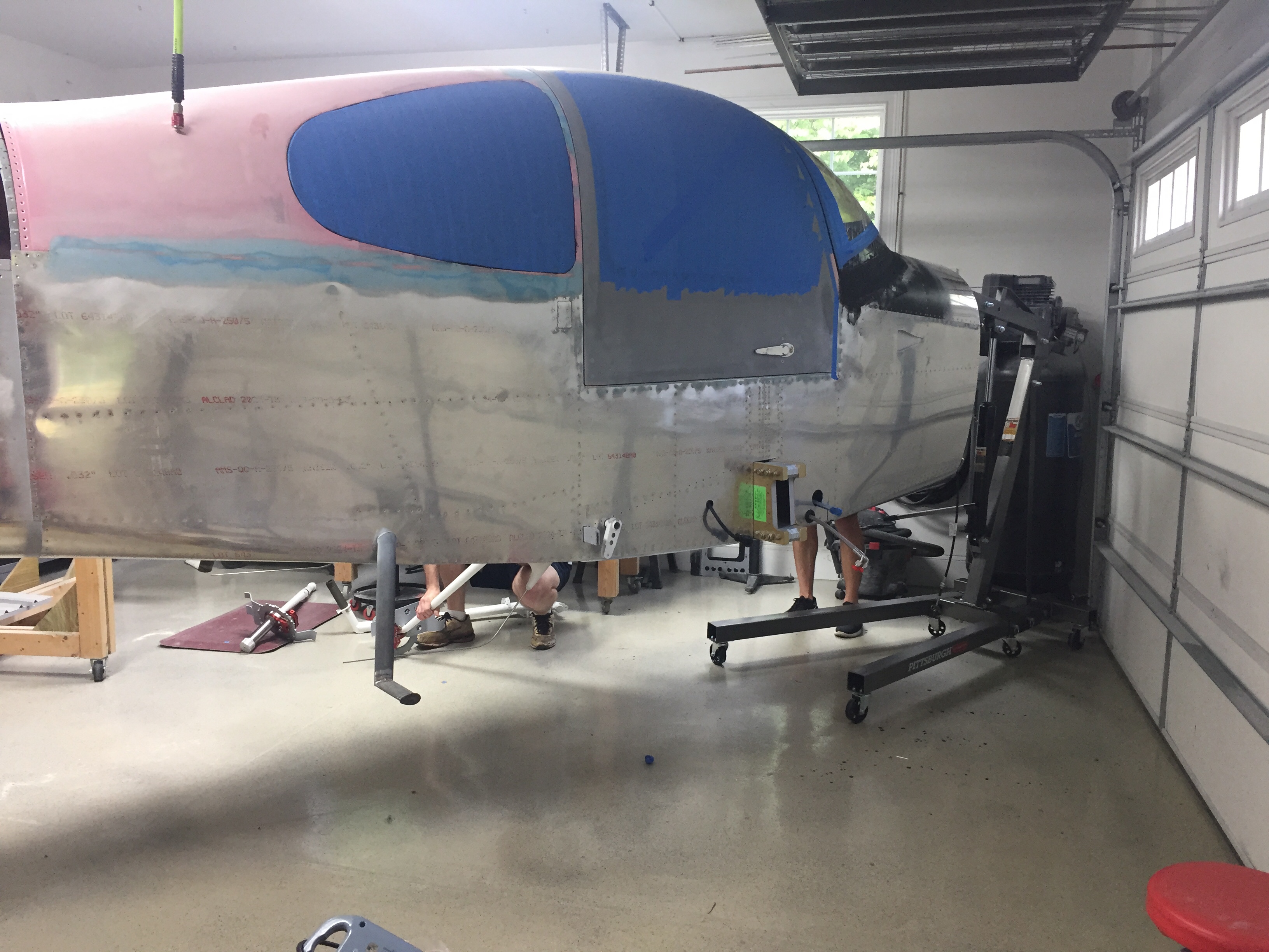
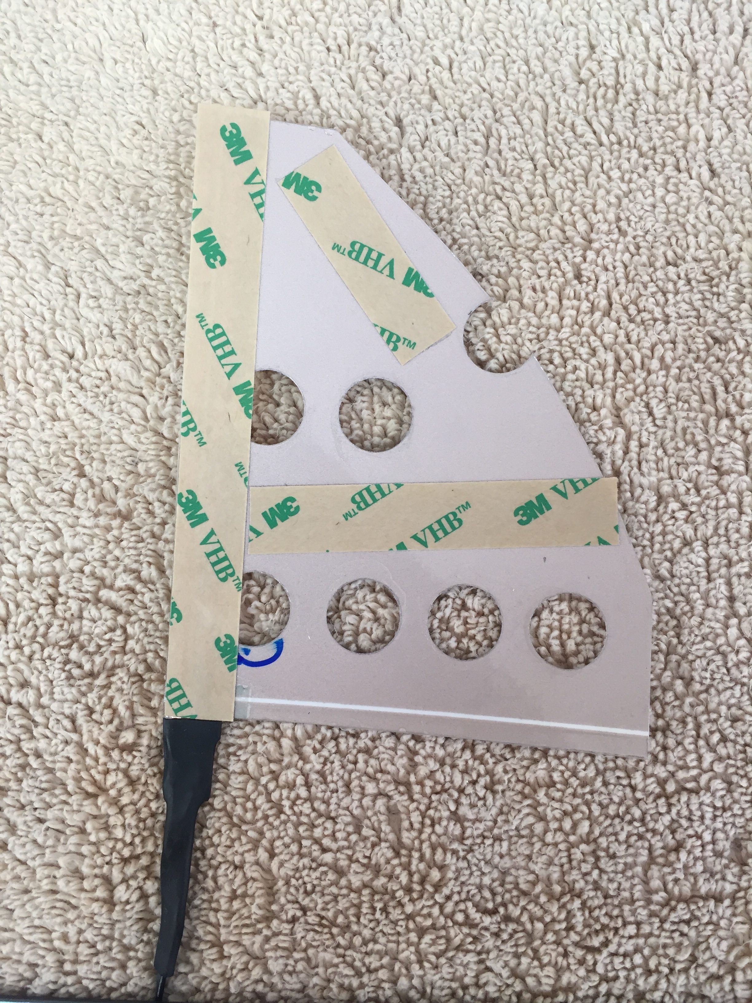
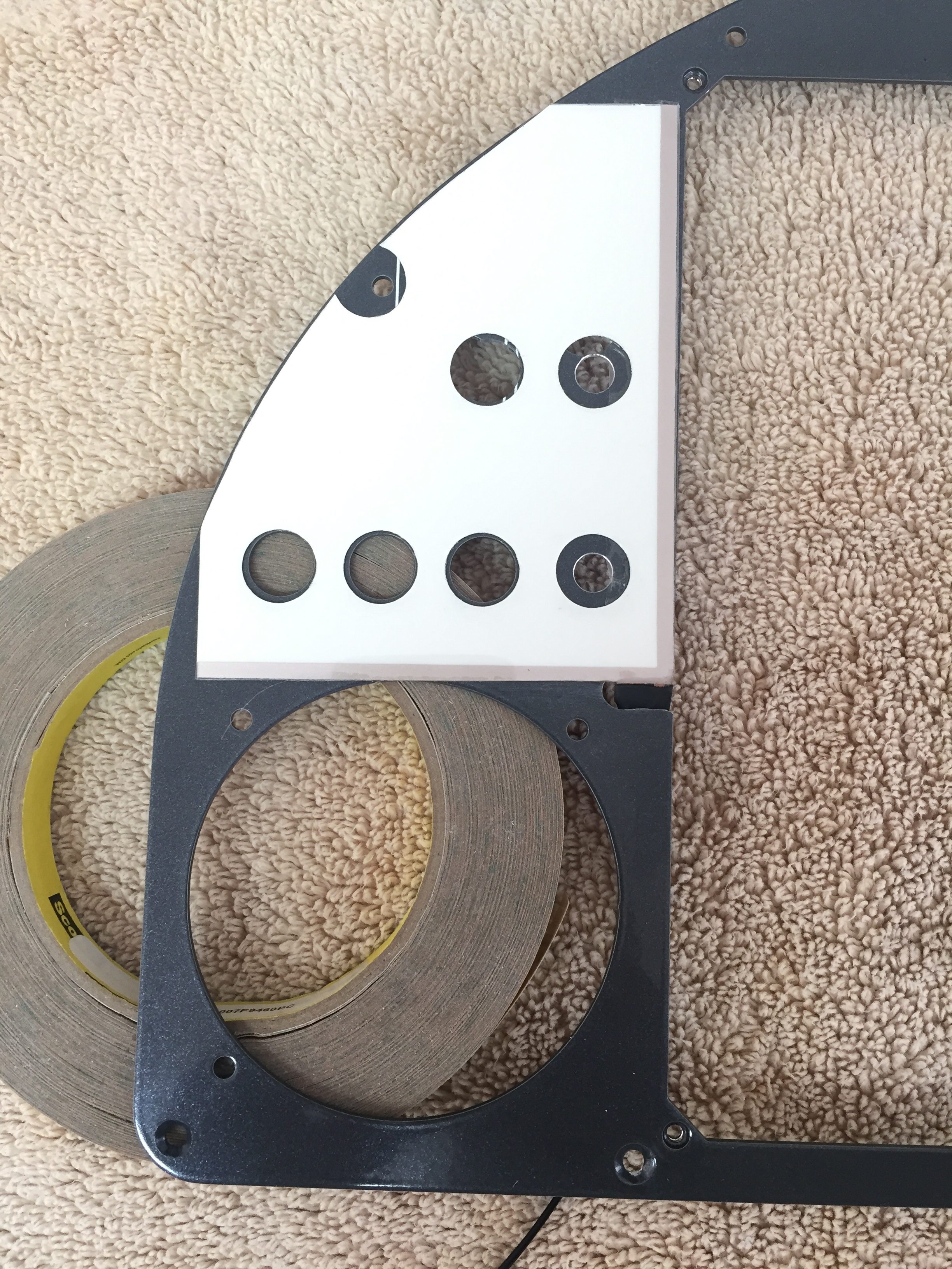
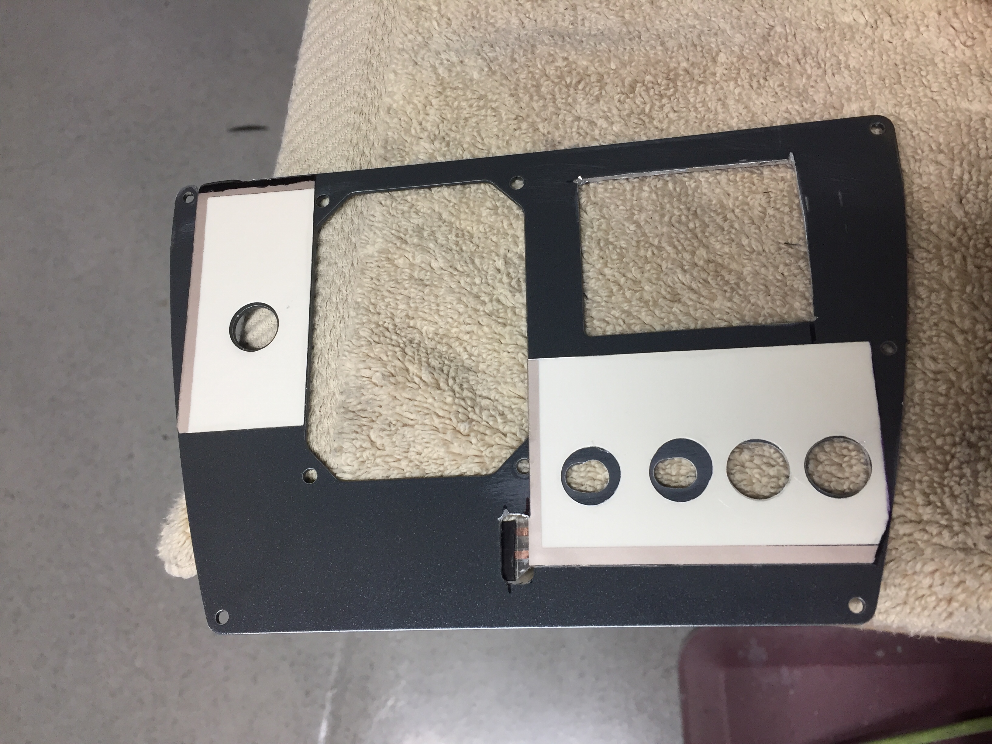
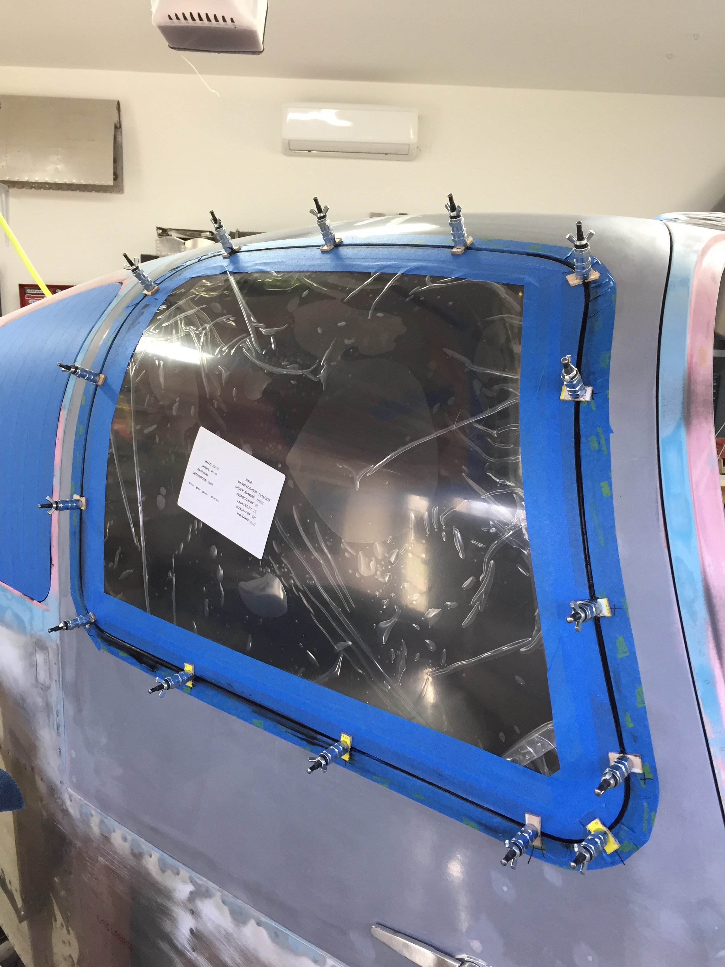
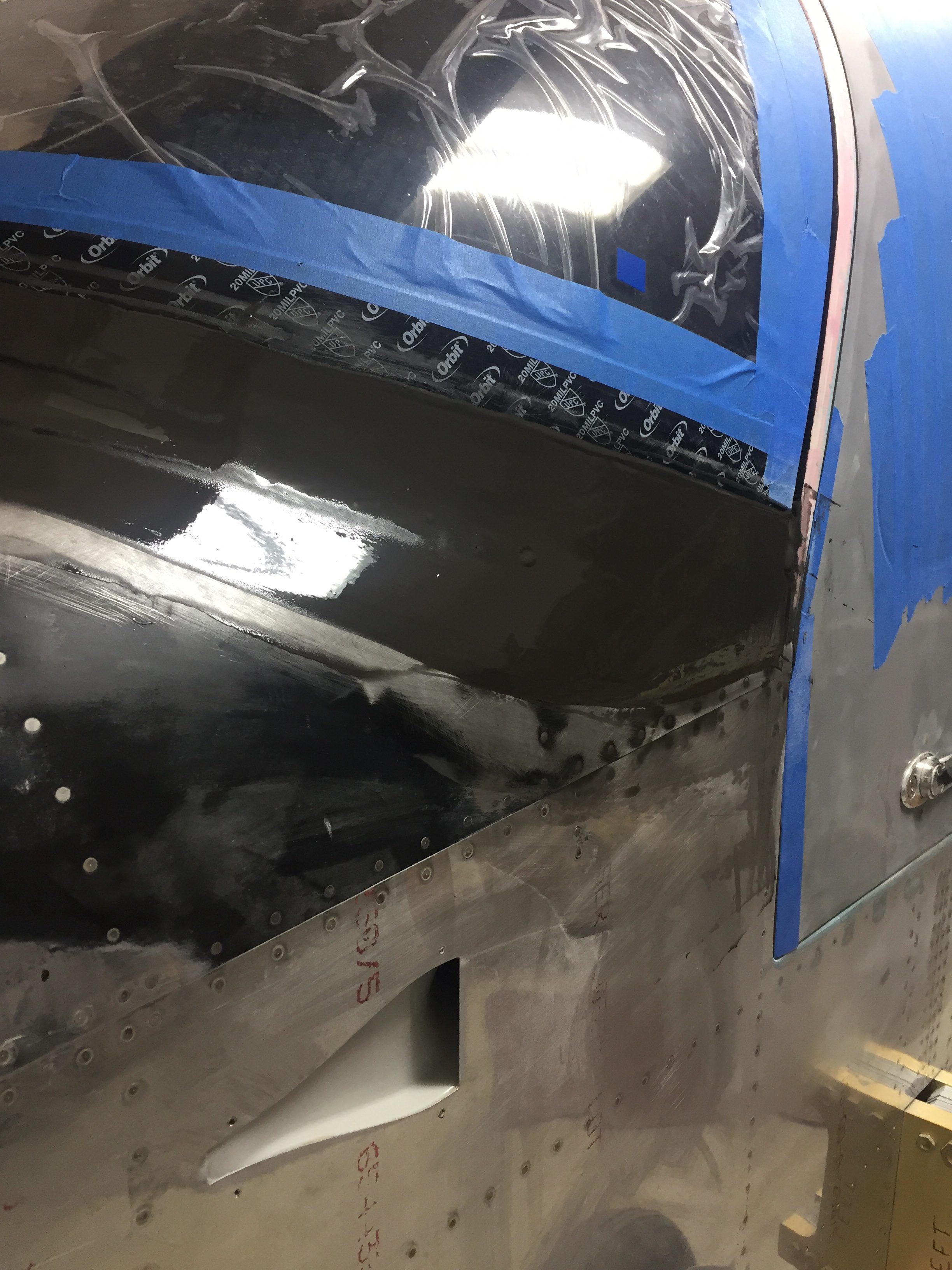
One of the last big fiberglass tasks is to layup the windshield fairing to the upper forward skin.  It’s a involved process with 10 layers of varying width glass strips followed up by a few coats of filler and epoxy to get it all nice and smooth.  I used cardboard to make a 7″ radius template and cut all of the fiberglass in preperation to layup the fairing.  I took other’s advice and died the epoxy black that will help create a nice finish from the inside with the Sika primer painted on the plexi.  This avoids unsightly views of the fiberglass from inside the cabin.  No pictures of the process as I had epoxy and fibers all over me, but it was a long afternoon with a lot of mixing.  I found that it was difficult to keep the layers precicely on top of each other and wound up with a few lumps and bumps along the way.  All were under the template radius, however, so could be fixed with filler.

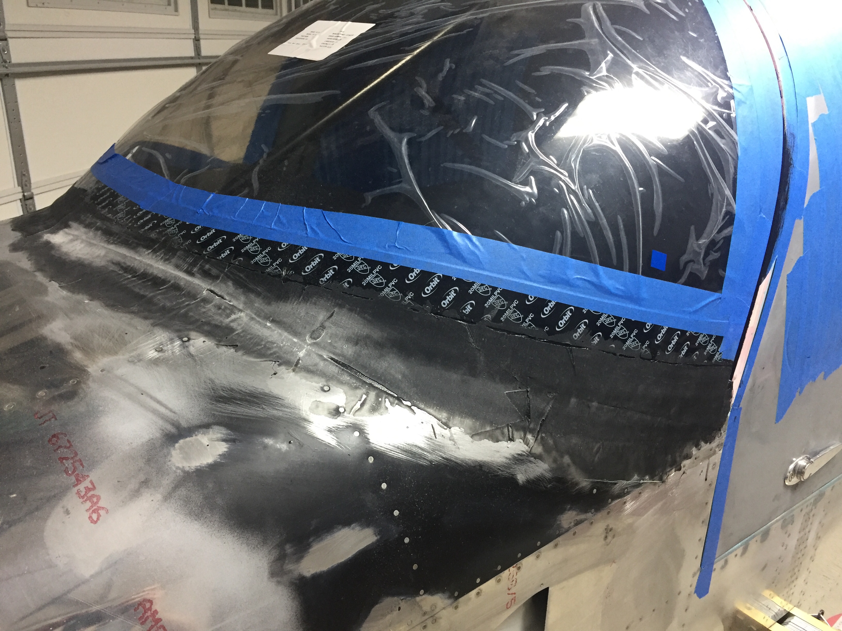
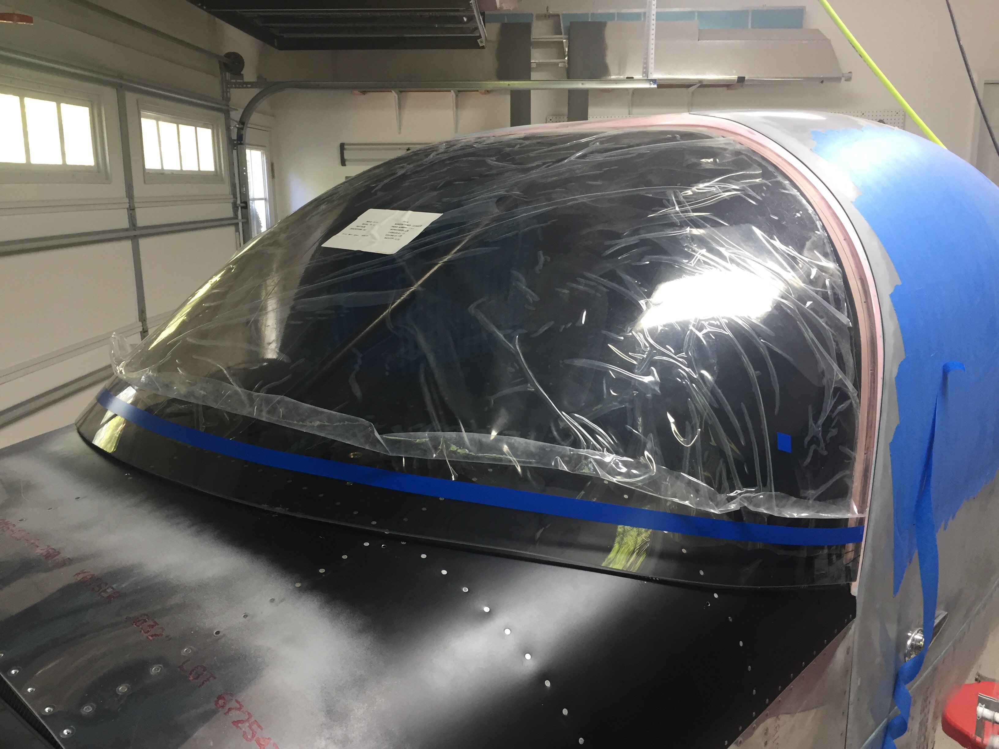
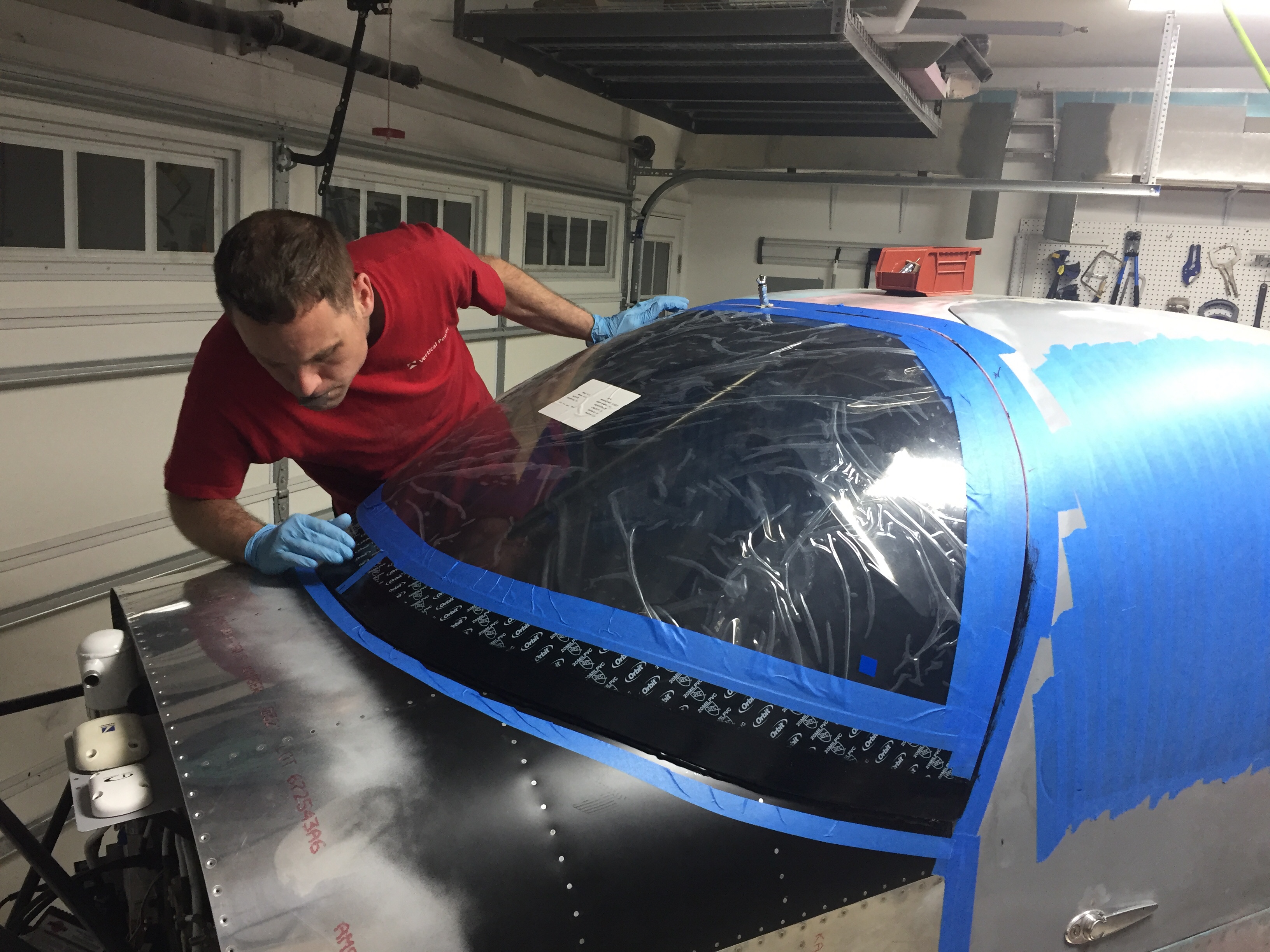
The layup turned out pretty well and the next step is to apply filler.  I ordered a 2 mil vinyl plumping tape from Amazon Officially Approved Totally Legit Aircraft Supply Company and applied that over the electrical tape that marked the edge of the fairing.  This is probably the hardest aspect, as getting a nice smooth and even line is a bit challenging.  In the end, I did a lot of measuring and then eyeballing to get it good enough.  It probably isn’t perfect, but it looked good to my discerning eye.

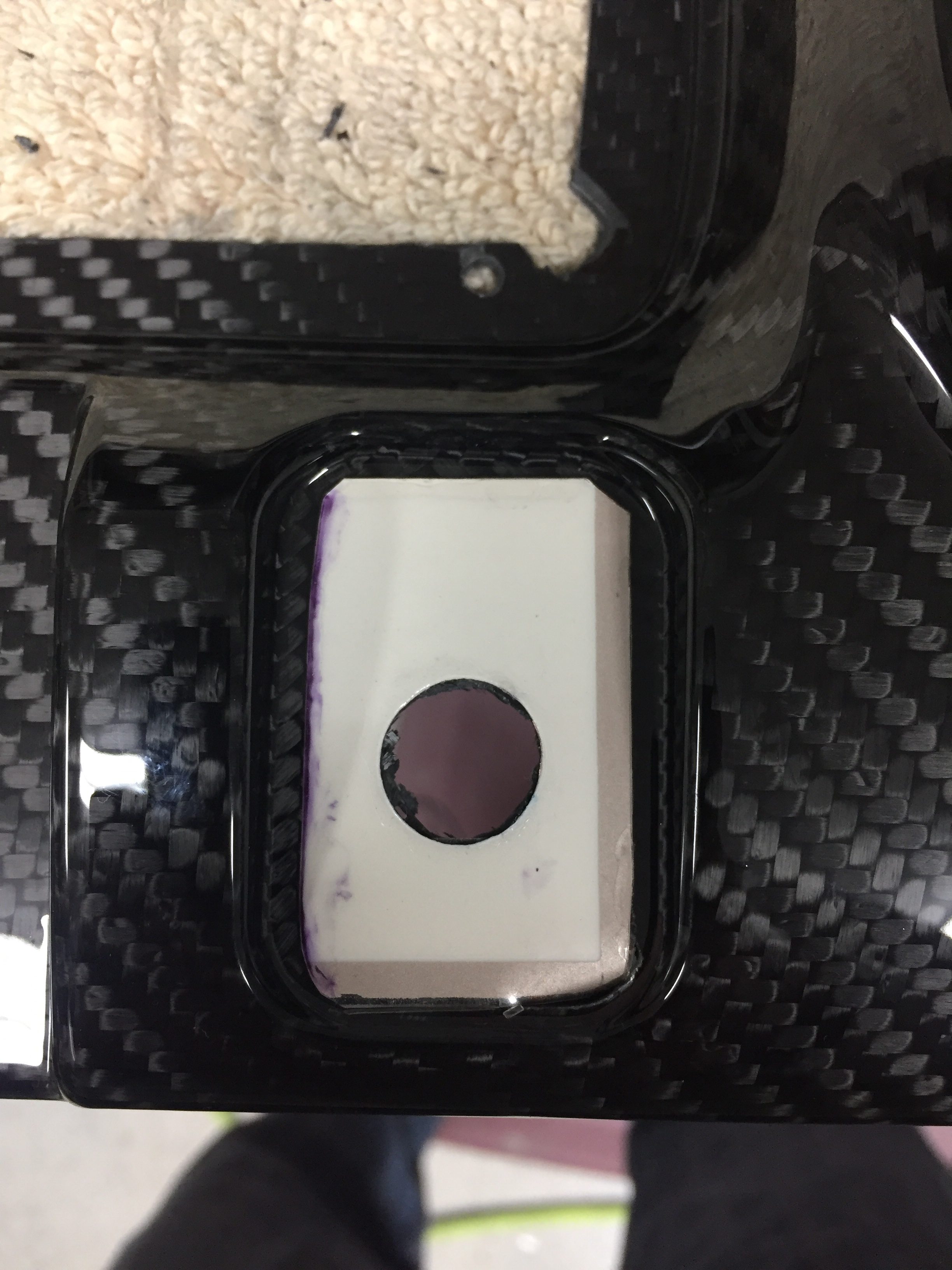
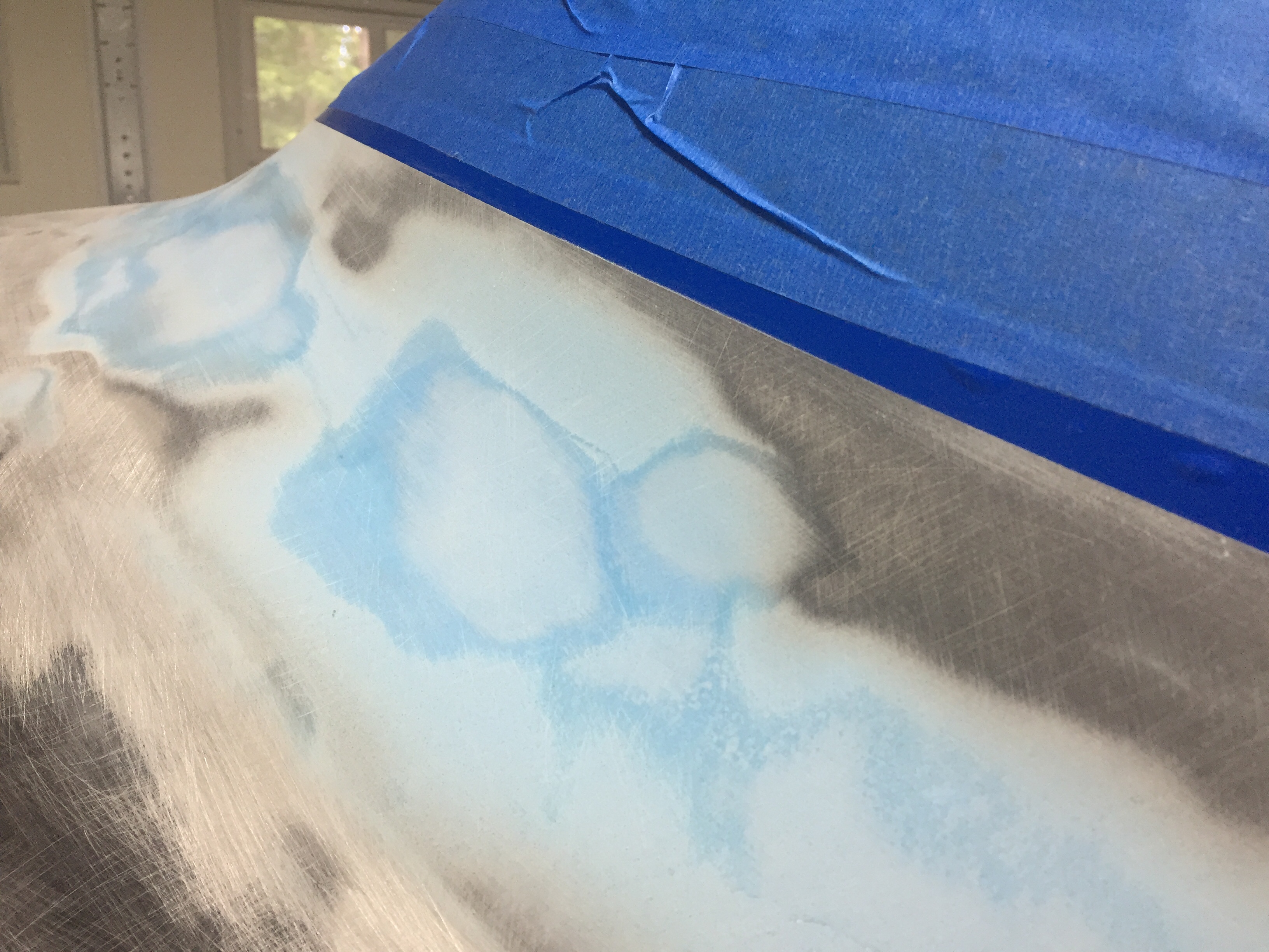
My first coat of filler was the West epoxy mixed with micro to give some good ridgity over the layups.  I died it black just be be sure a good coverage again and made it good enough under the template.  After a quick sanding once dry, I used SuperFil to complete the curve which is much easier to apply and sand.  All in all, it took about five applications to get everything just the way I wanted it.  I used my favorite soft curved sanding block to sand and just judged by feel any high or low spots.  I’m happy with the turn out and I’m sure Jonathan will touch it up when he takes the plane for paint next year.

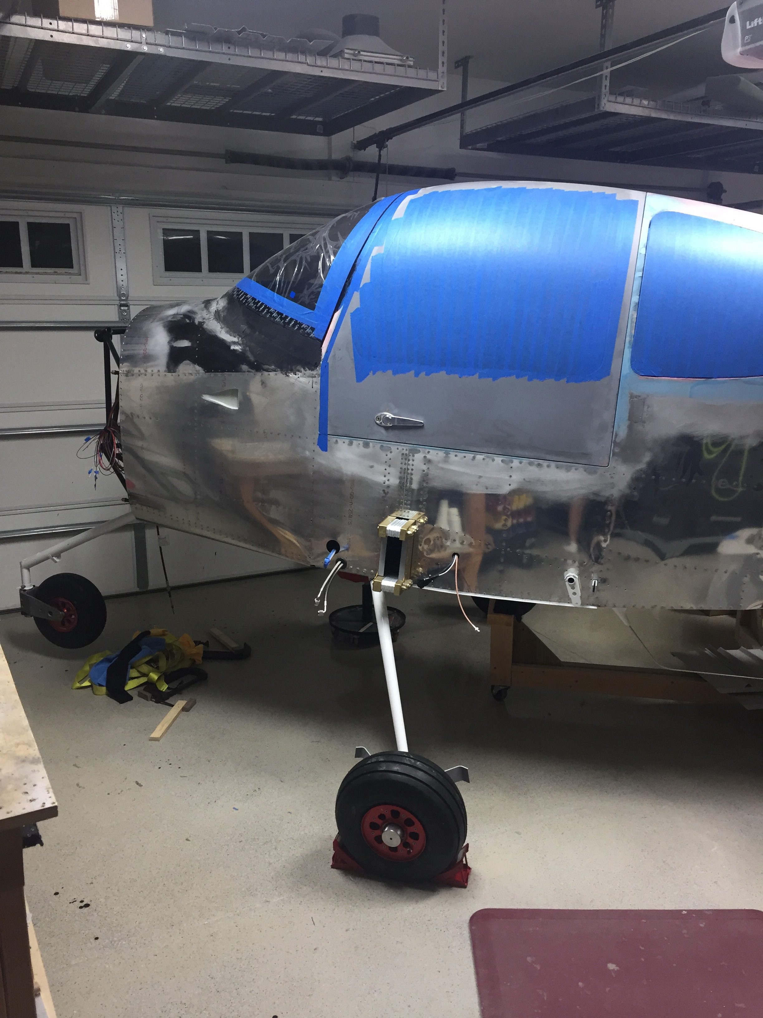
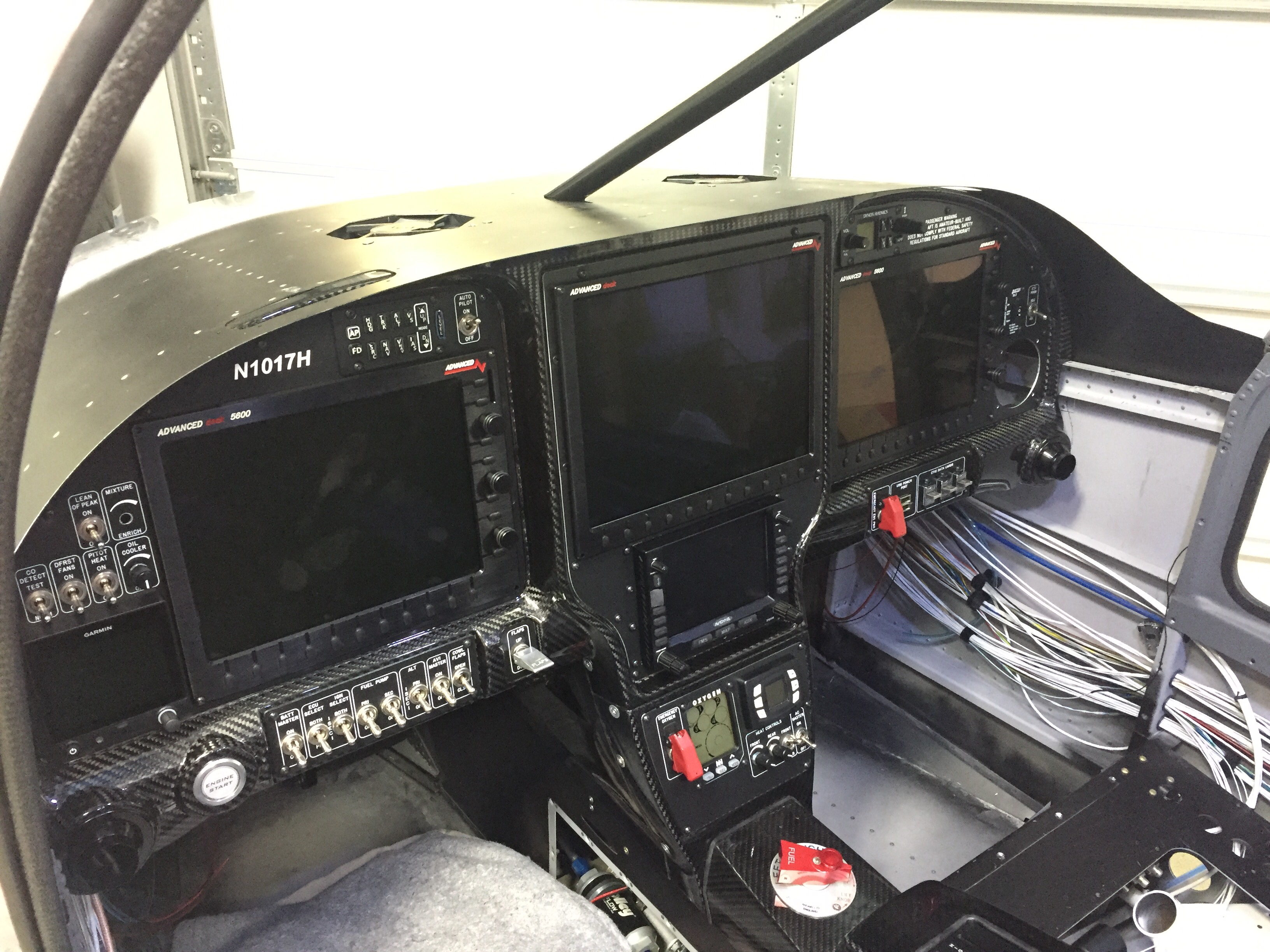
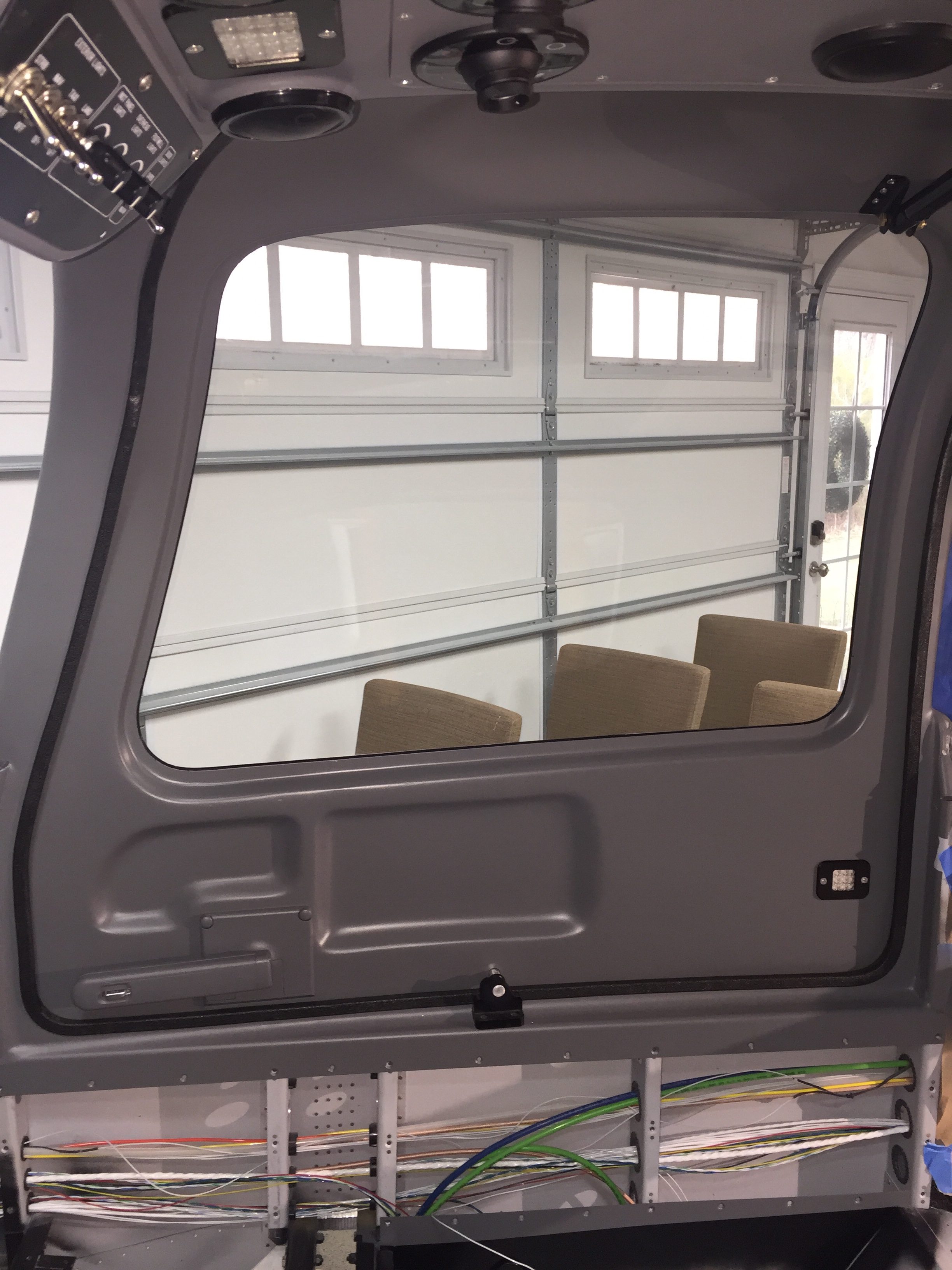
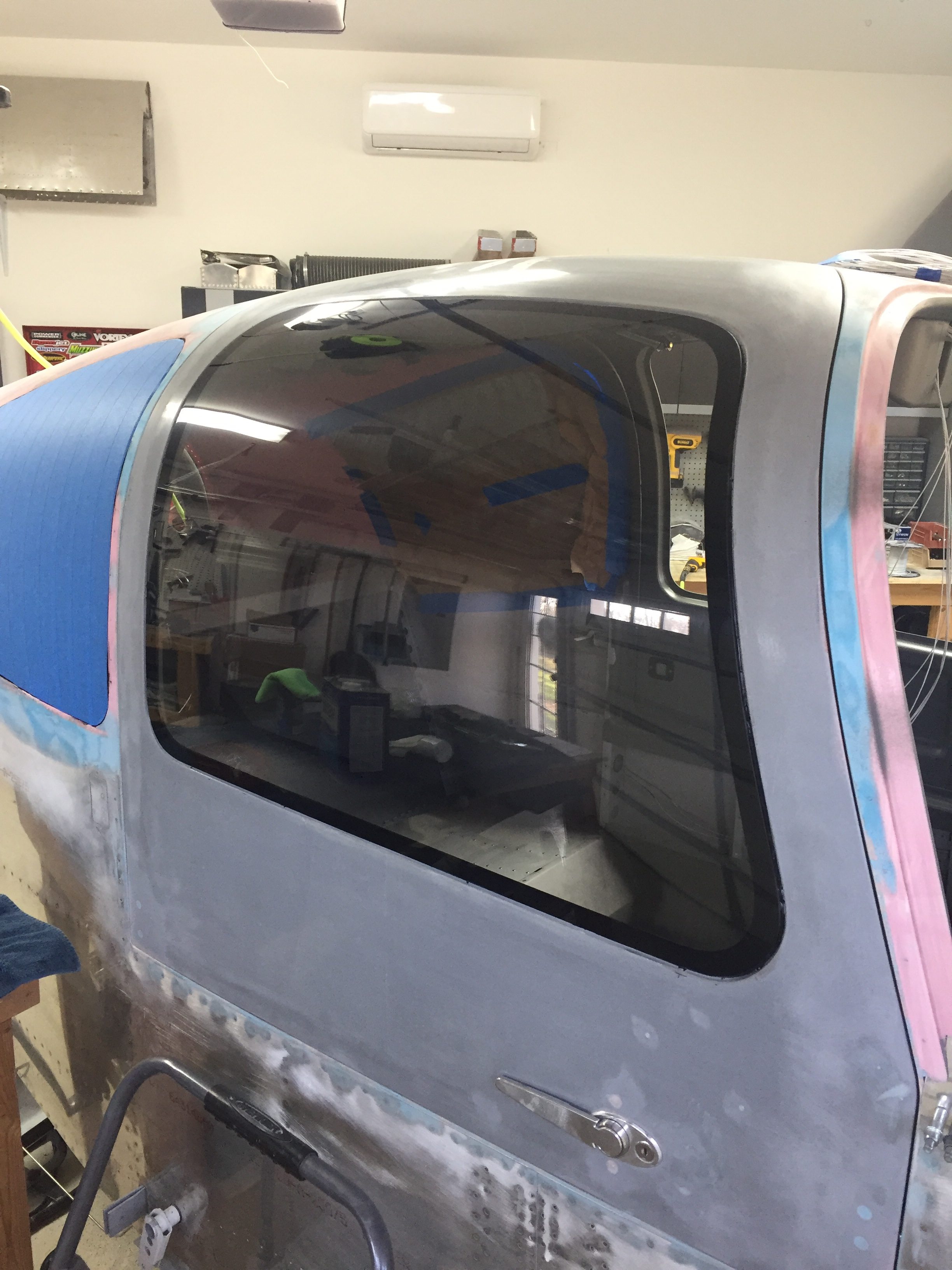
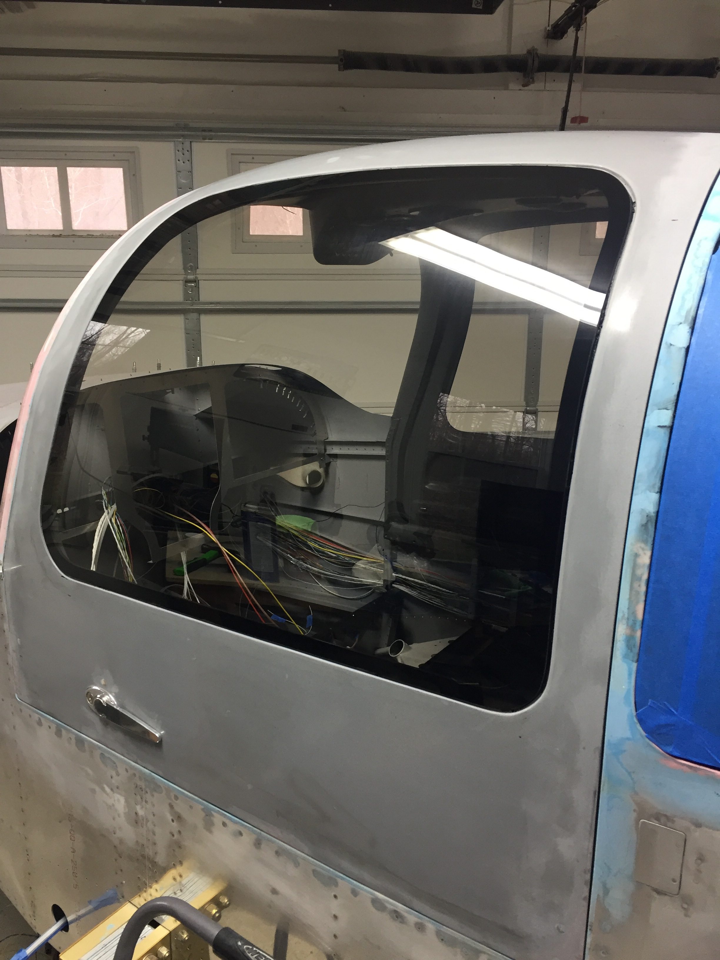
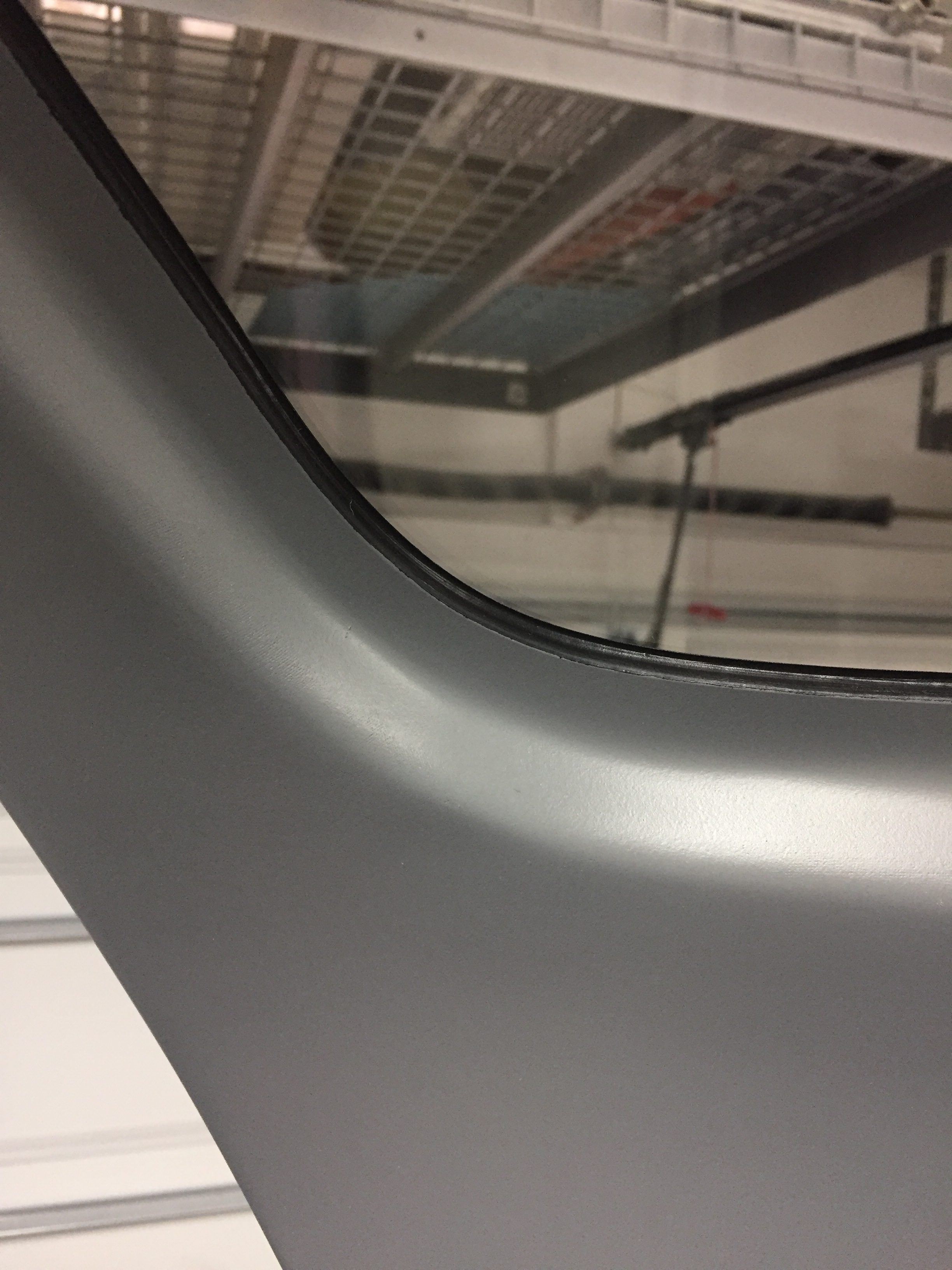
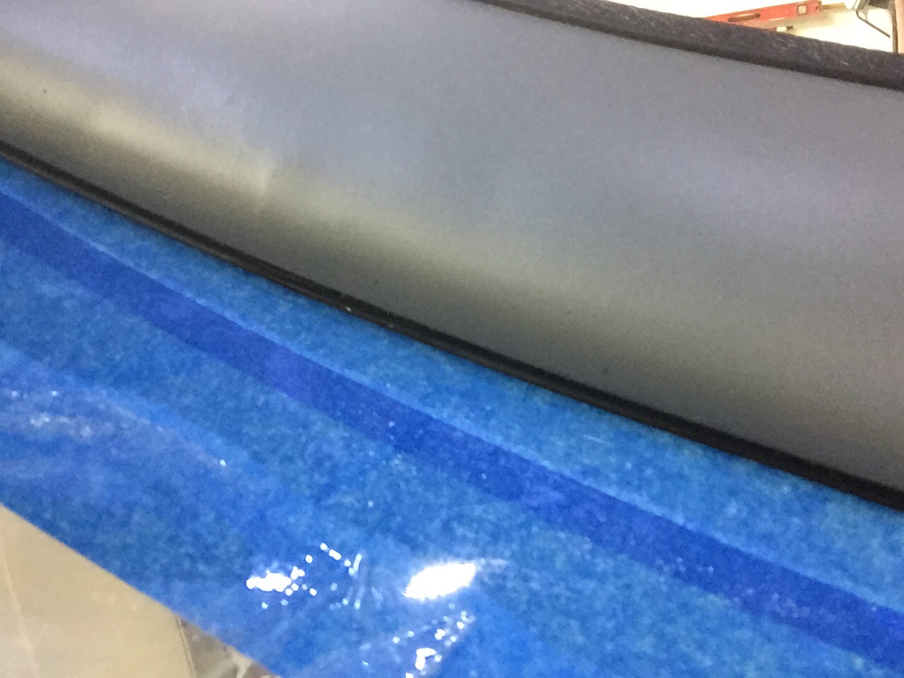
On the inside, I have one little streak of white from the tape which is a bit aggrivating, but nothing I can do about it now.  It may be covered by the side panel and glareshield, so not too worried about it, but it just annoys me.  The rest of the windscreen interior turned out absolutely perfect.  Again, the Sportsman method of taping and using Sika was a huge aspect of getting a clean finish.  It’s really cool to sit in the cabin now and look out through the windscreen!  It’s also nice having the cabing almost entirely closed in to keep it clean.

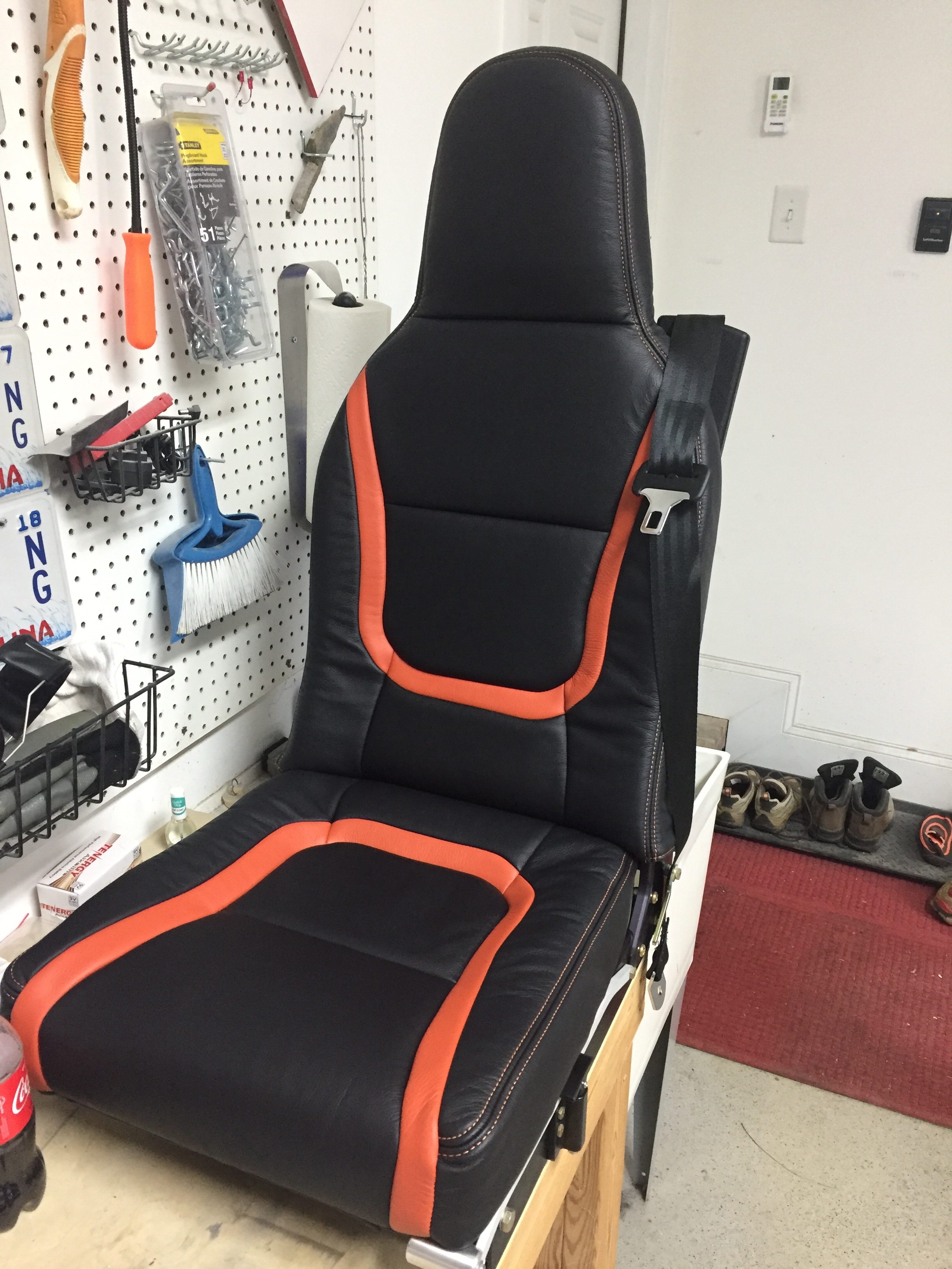
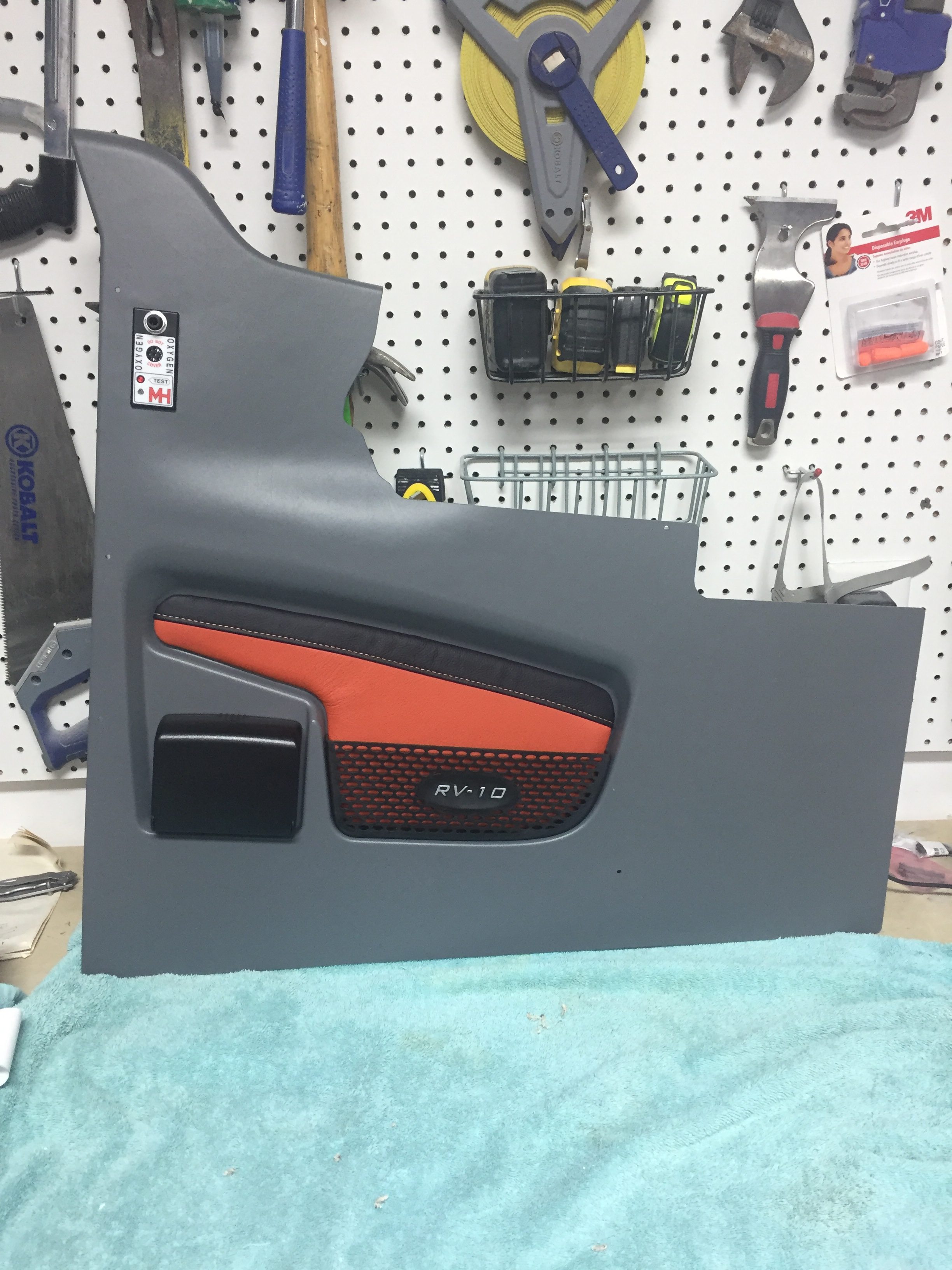
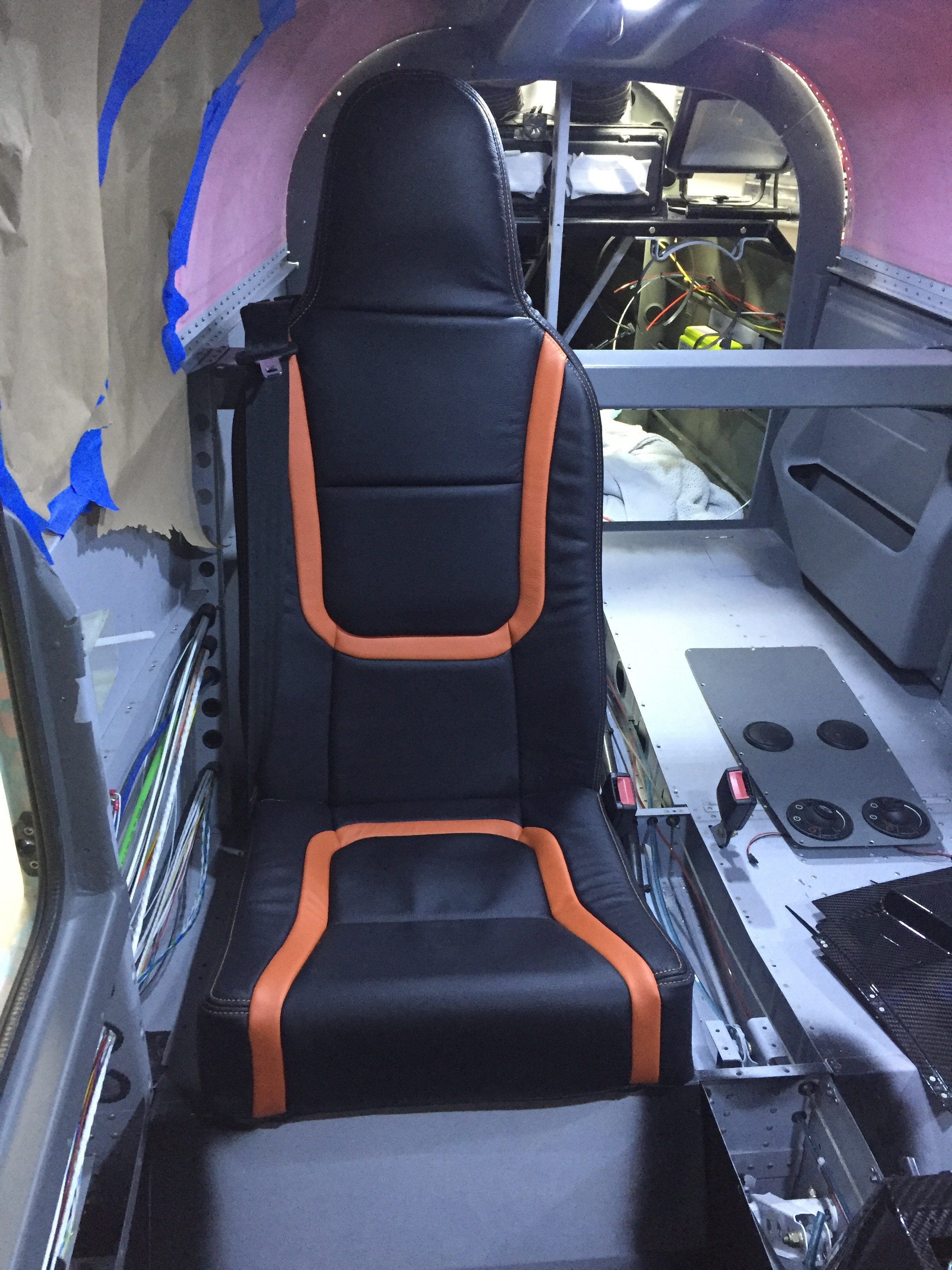
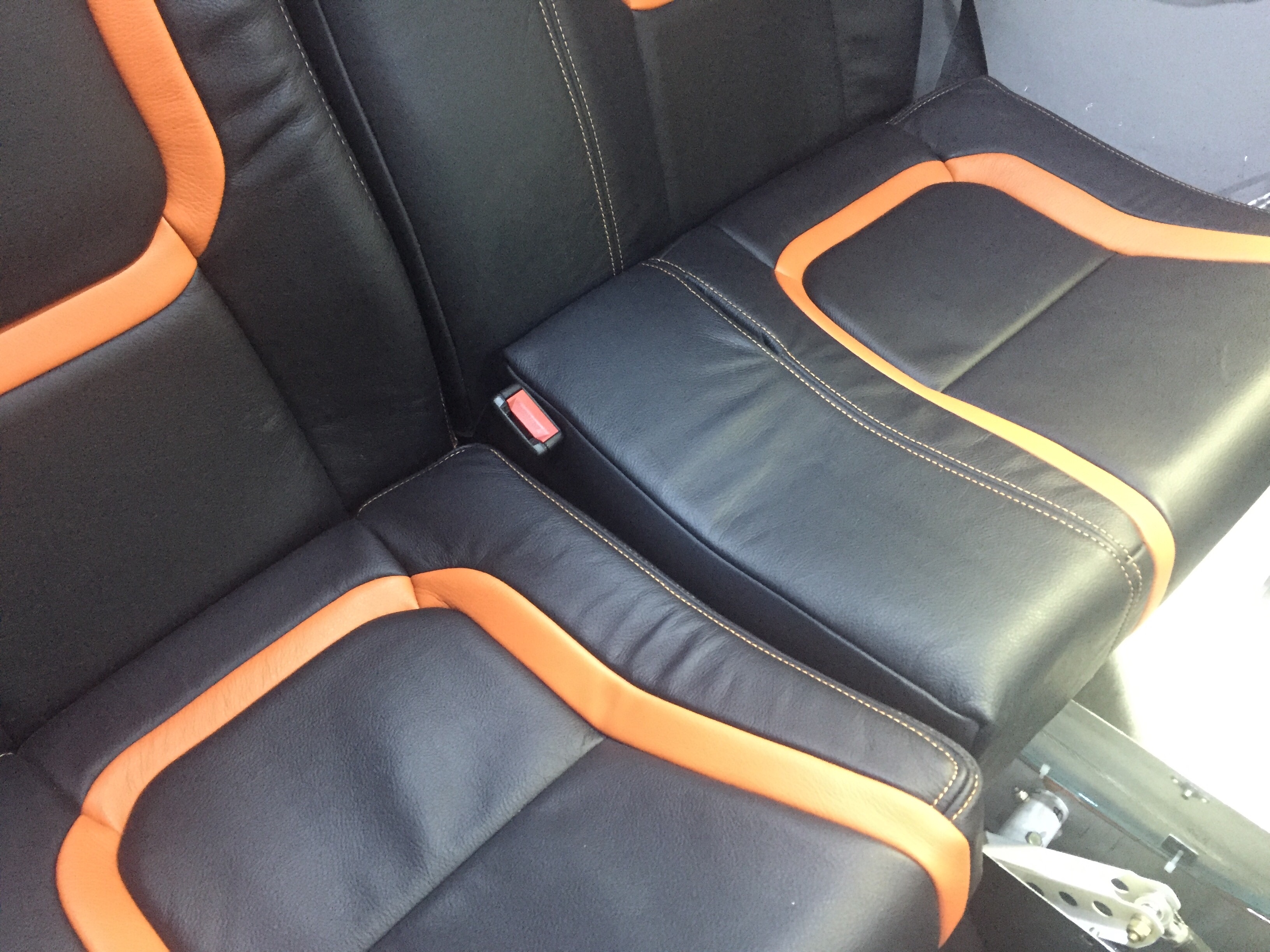
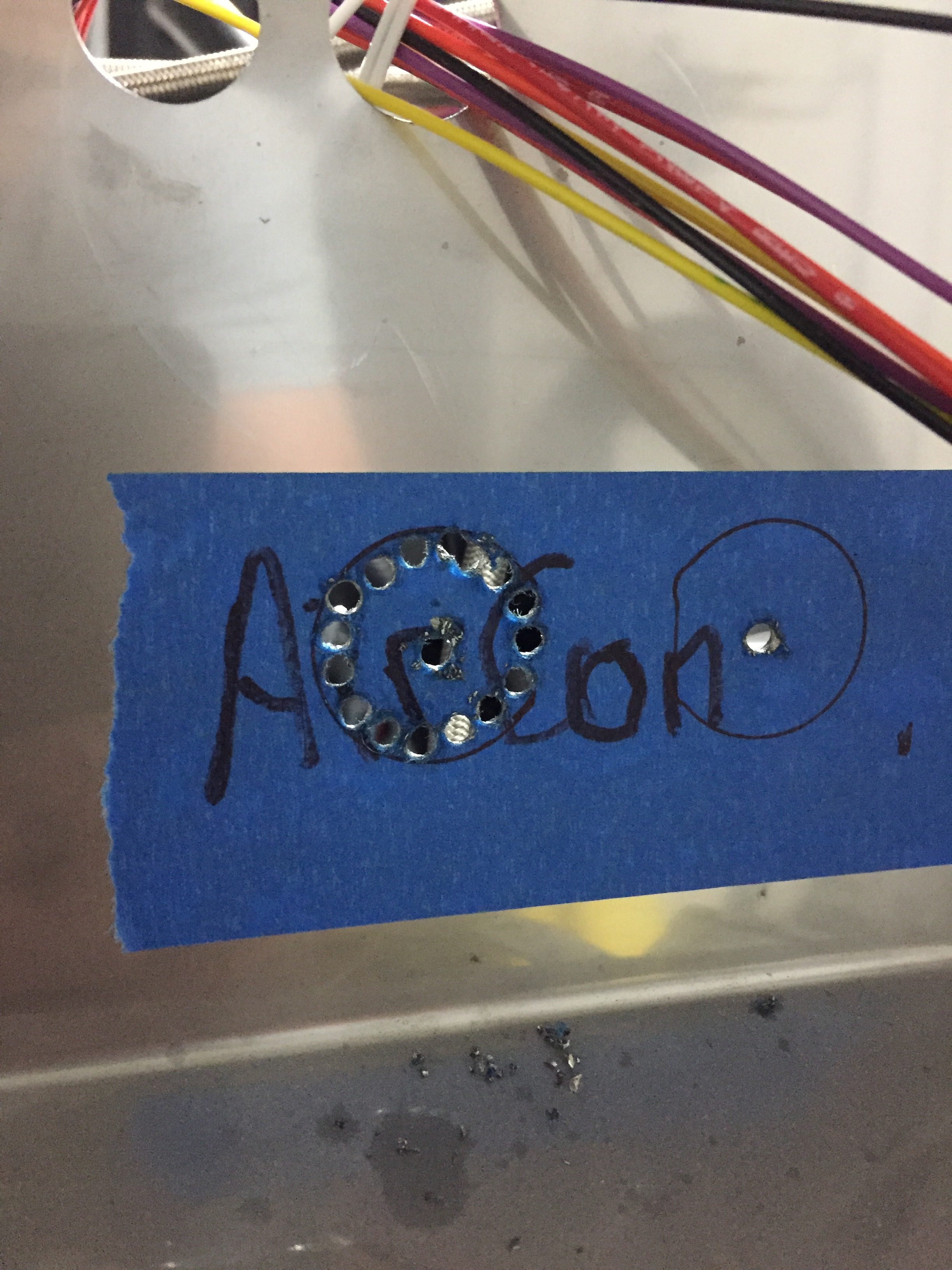
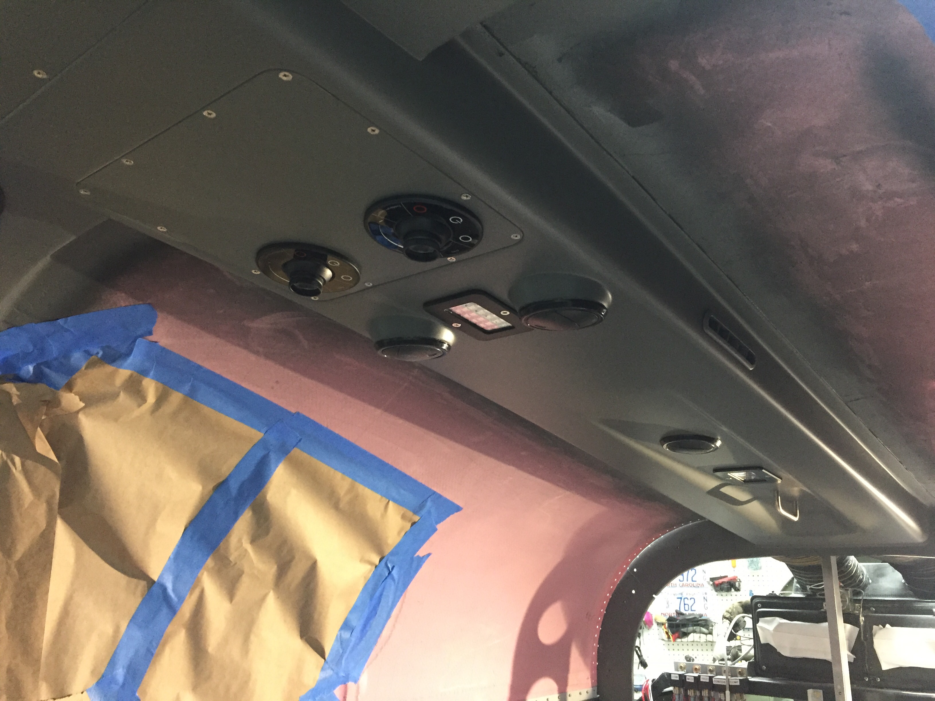
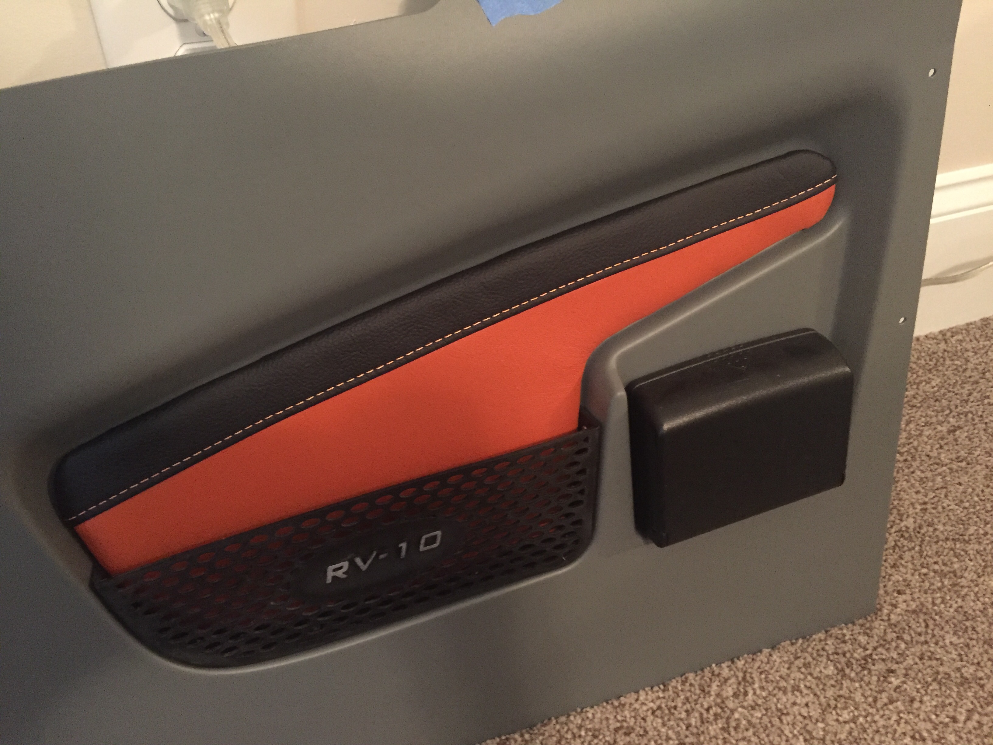
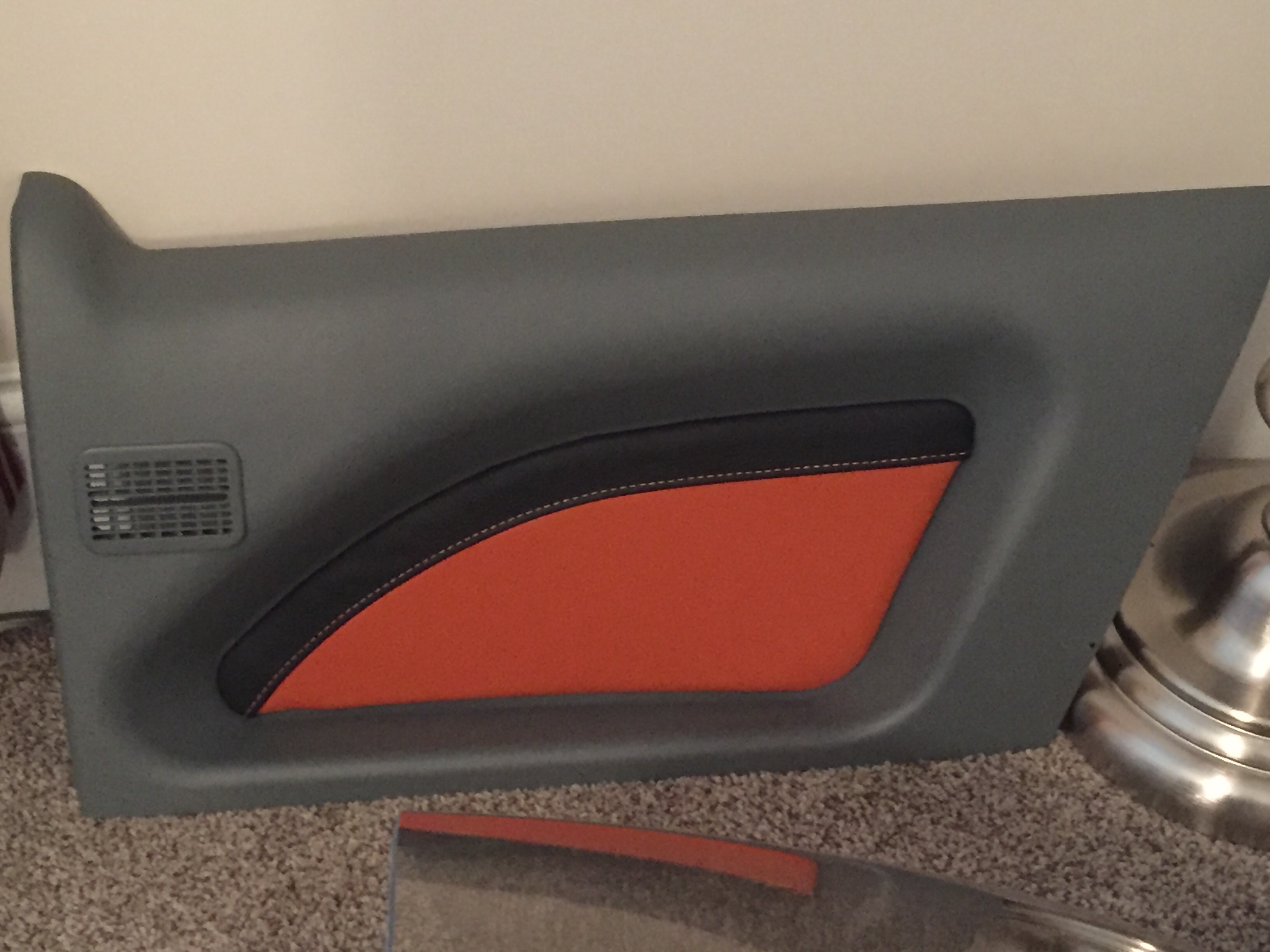
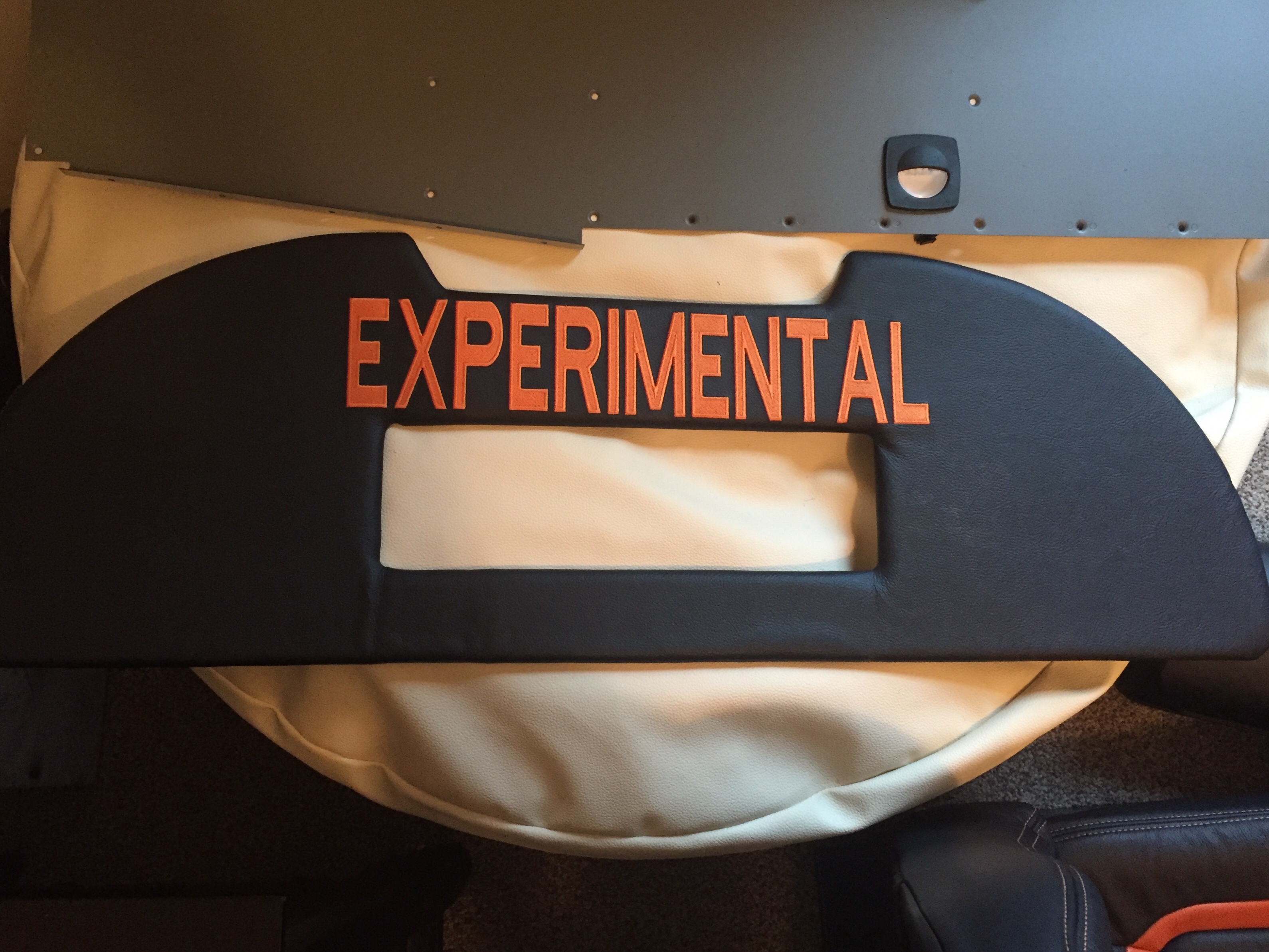
I am getting the last bits of interior from Aerosport and putting them in place as I go.  The panel inserts came with the seats and turned out great.  They are easy to install and really add a bit of class and color to the interior.  The baggage bulkhead looks great as well with the EXPERIMENTAL embroidered on the leather.  I’ll be putting a mesh grille in the cutout for the aircon return vent.

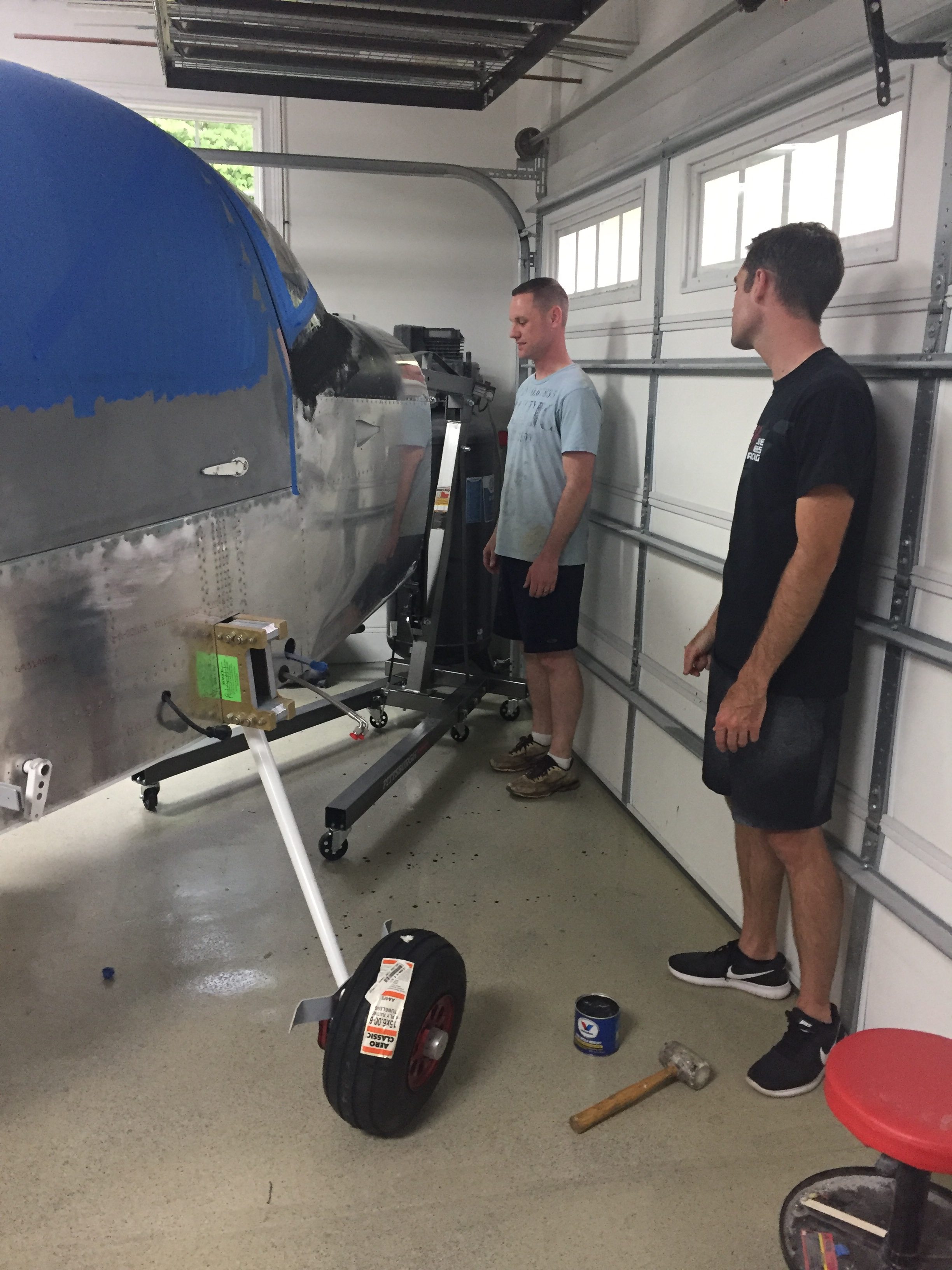
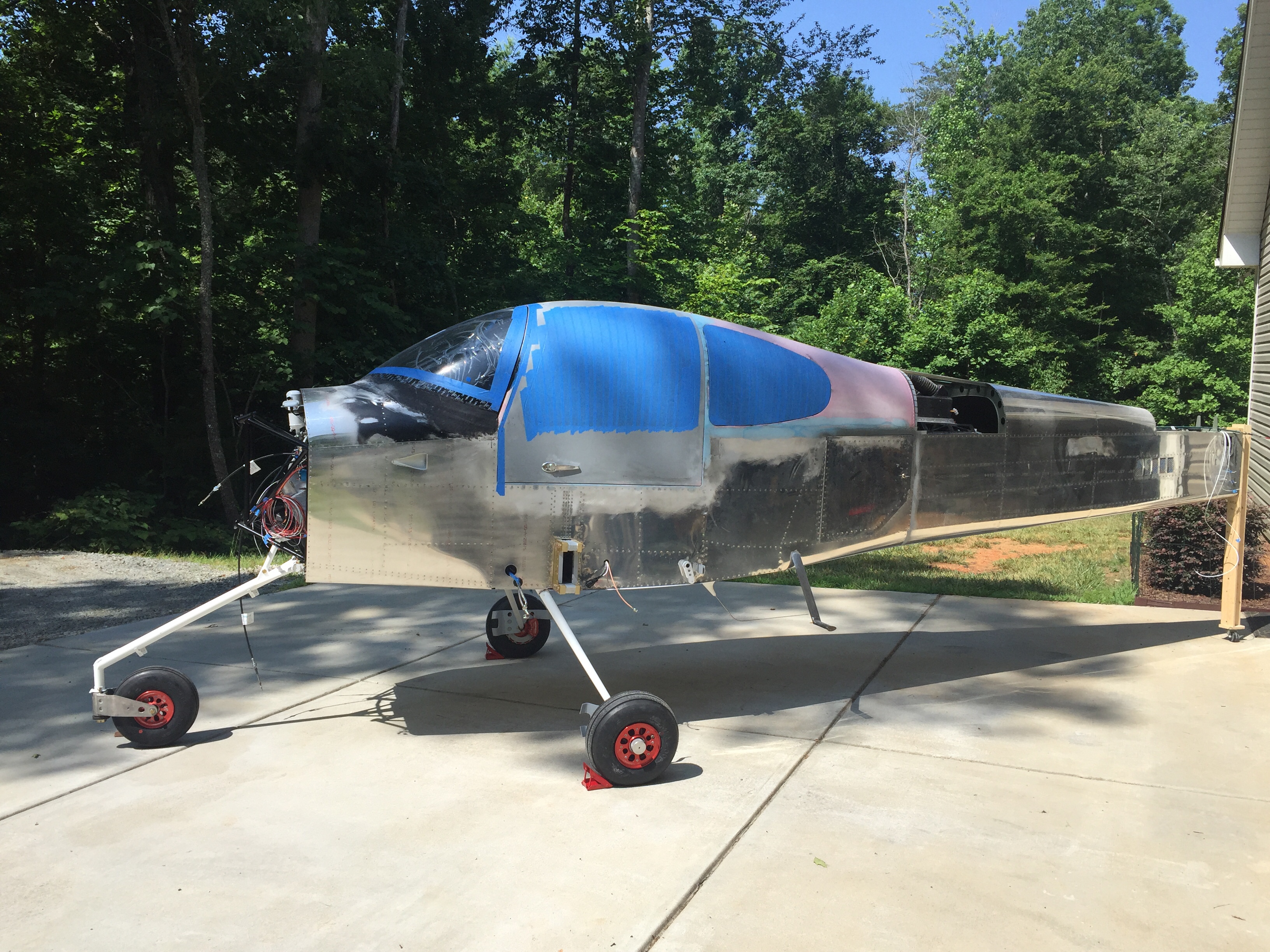
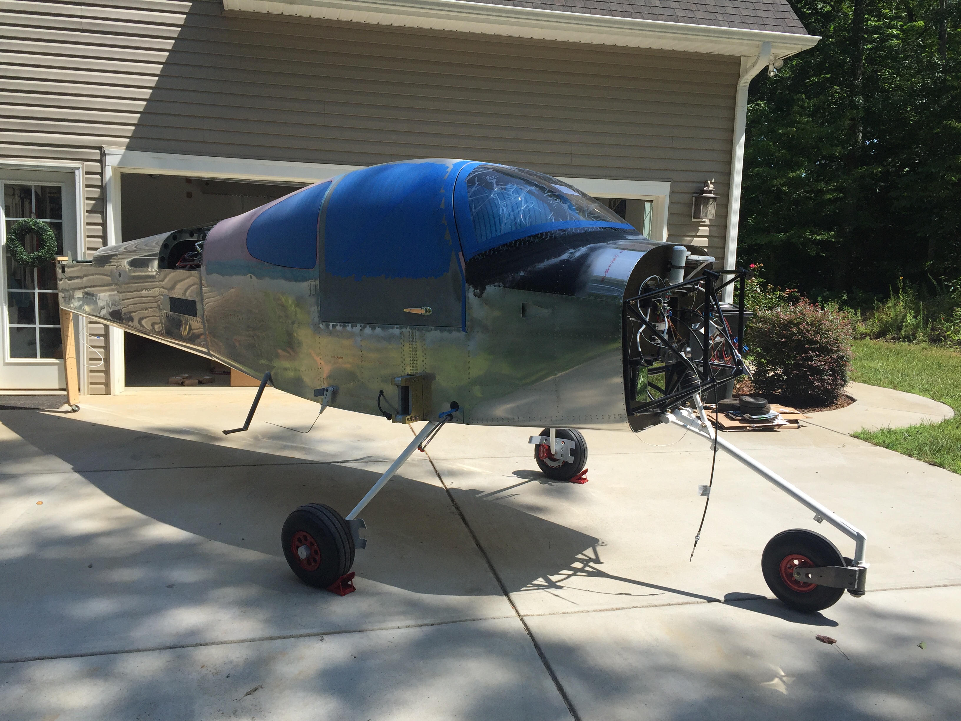
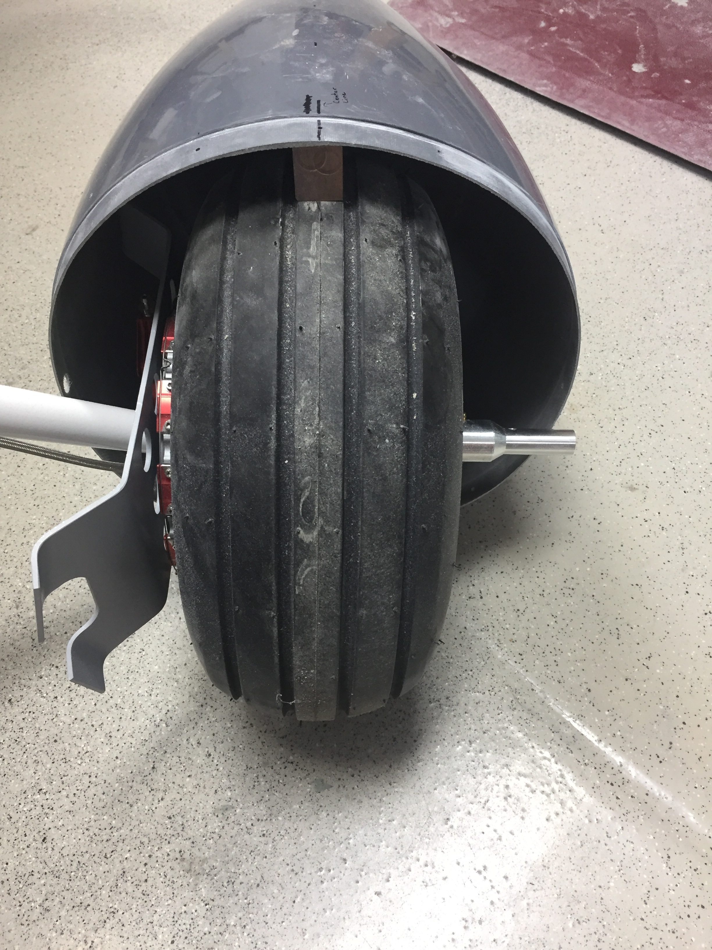
I finally got started on the wheel pants as well now the gear is on and it’s exciting pulling more parts down from storage.  I really want these pants to be finished well and have a nice fit, so I’m taking my time prepping the seams and mounting points.  I’m going to use SkyBoltz instead of traditional nutplates to allow quick removal and installation of the pants.  I don’t plan on having access doors for the valve stems because I just don’t want to do the fabrication neccessary.  This way it forces me to have a good look at the tire and brake while checking pressures monthly.  FYI the SkyBoltz are far cheaper direct than from ACS.

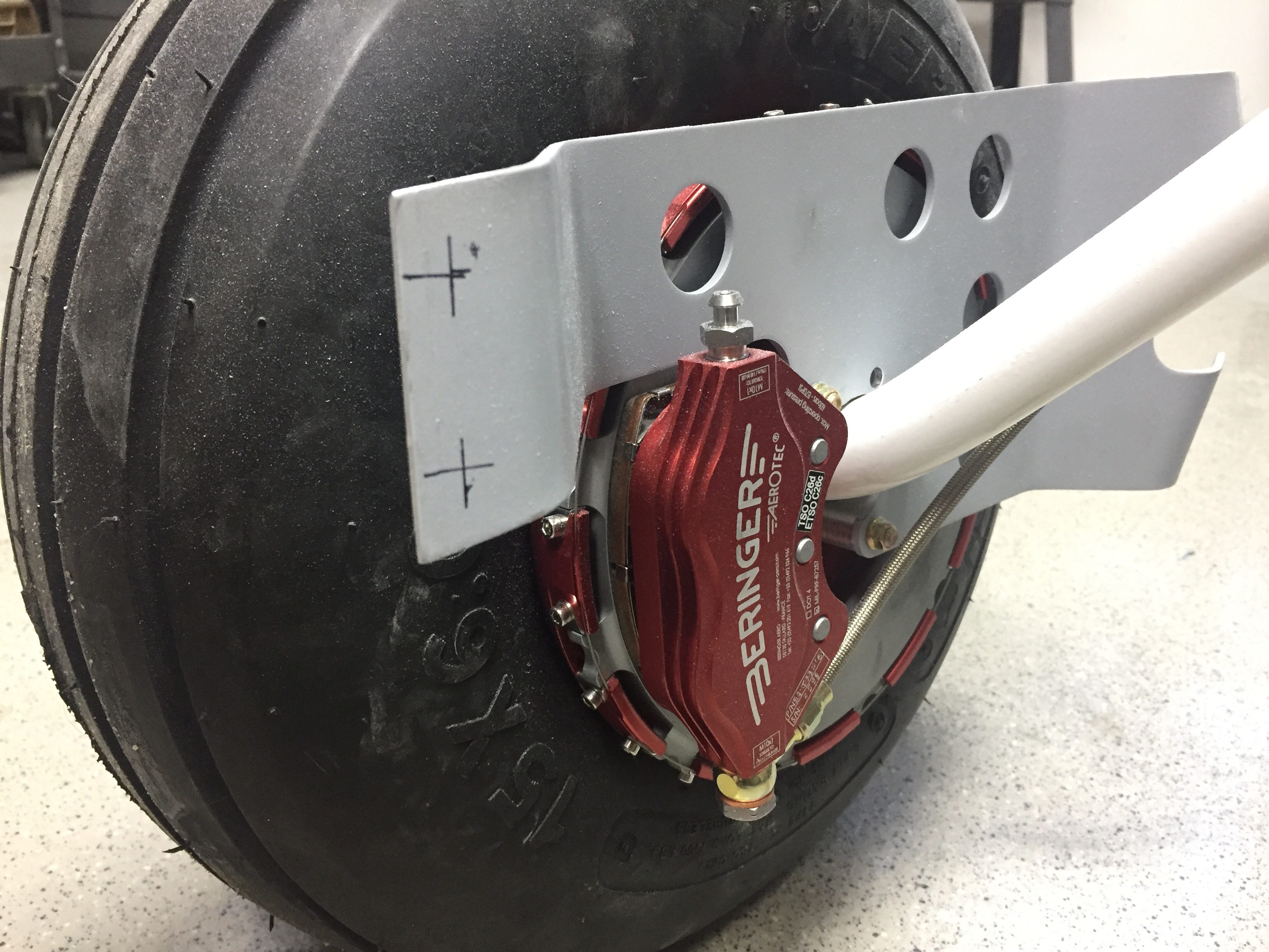
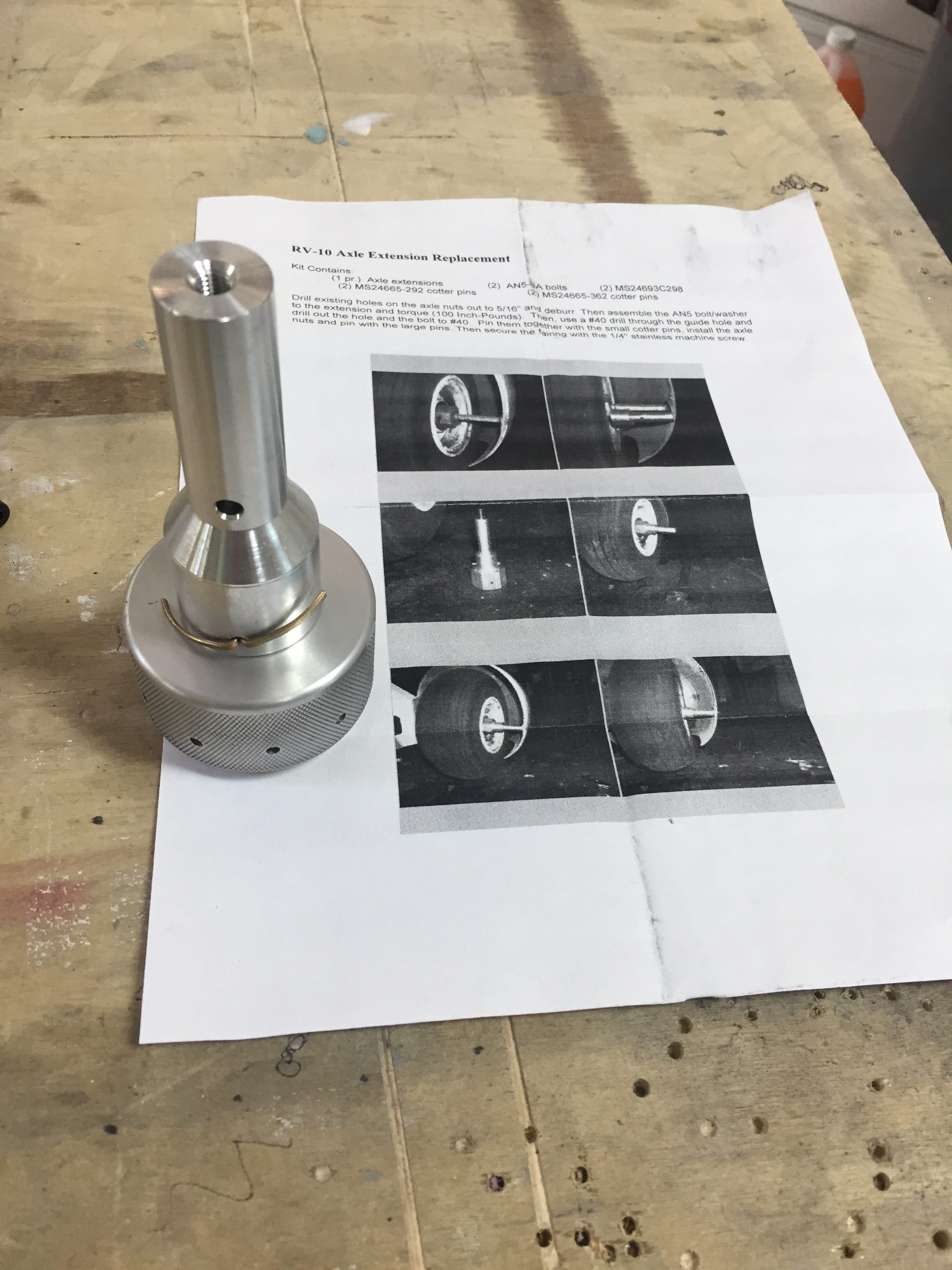
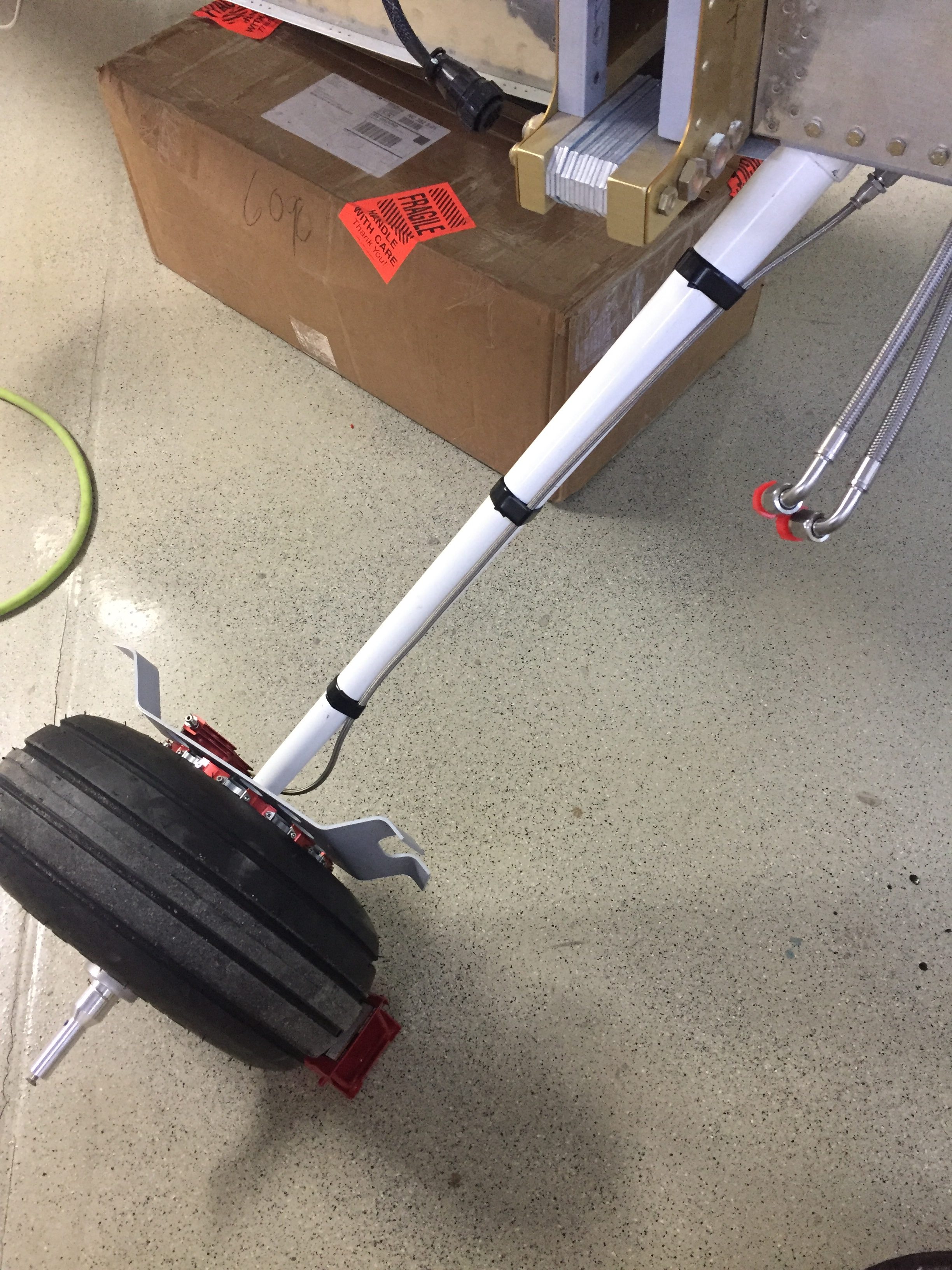
One issue I had to pause on and get some help was the wheel pant spacer that bolts onto the wheel nut for the main gear.  On initial fit, it’s proving to be way too long and I was hesitant to cut it allowing the rear portion of the pant to fit.  Beringer says trim away, however, so I think it’ll actually save me a few steps later in the process since I’ll be able to trim at a precise angle to match the pant and avoid using flox to build up a flange on the inside of the pant.

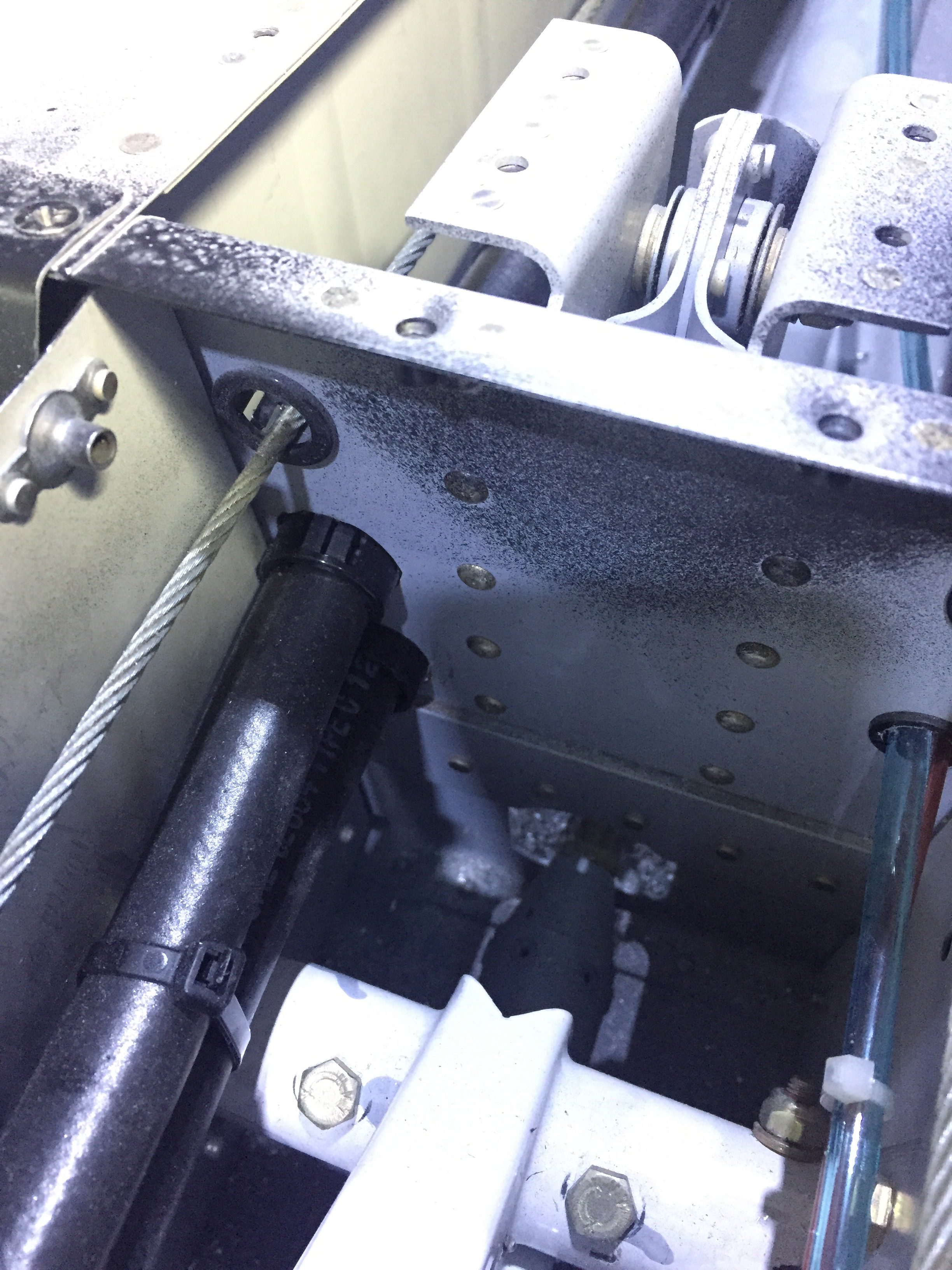
Meanwhile, I fabricated the last of the stainless steel brake lines and installed them to the calipers.  I am now considering swapping the calipers from side to side which will put the bleeder nipple on the bottom.  I’ve always had the nipple on the top of the calipers, but using a pressure bottle to bleed the brakes from the calipers up will allow the air to be pushed up naturally instead of forcing it down and the nipples should be the lowest point in the system for this.  If the lines can still be used, I’ll swap them.

Next up is some exciting stuff as we jet off for vacation and engine build school in Kamloops, BC.  Stay tuned for details!

She’s got legs!

I continue to empty my parts inventory which is nice to give the space back to what it should be such as guest bedroom and bonus room upstairs.  A big chunk of floor space has been taken up by the windscreen.  Now, the story is I received my order from Cee Baileys many months ago but the box was damaged and the thoughtful FedEx driver decided to take the bundled plexi out of the damaged box and simply lay on the diamond plate steel floor before continuing the route.  Needless to say, my brand new windscreen was no longer brand new.  It’s not to say that it’s ruined, it just didn’t meet my standards.  I was lucky to only have a few tiny nicks that won’t even show up on a camera picture, but are visible if you look hard enough.  A claim and call back to Cee Baileys had a replacement in a better box on the way to me.  I plan to sell the original one at a good discount and it may work for someone building on a budget or as a repair, who knows.  Either way, my fuselage was ready for a windscreen.

I prepped it just as I did on the windows and since I had already rough trimmed it, I was able to get the final fitment completed in just one evening.  I’ll be using a mix of methods to install it, following the plans on the lower edge and using the Sikaflex method around the cabin top.  I again traced the edge of the cabin top onto the plexi so I could tape it using the sportsman method.  It was actually easier since I only had half the area needing taped.

I also ground down the two side corners of the plexi to allow a nice flat surface once the fiberglass layup is applied.  I’ve seen and heard others having a buldge on either side of the fuselage and most women find buldges unsightly and moderately annoying.  This is all about impressing the ladies, so no buldges on Tess!  I decided to apply the Sika primer on the outside of the bottom area to help hide the fiberglass overlay.  I also have black die for the epoxy.  Once the skin was roughed up, I laid a good bead of Sikaflex down and Laura helped me set the screen in place.

I worked quickly again to put the wing nut clecos in and level out the screen to the cabin top.  It went well and soon enough it was time to clean up the inside.  Again, time spent prepping the tape proved to be priceless, as the inside of the screen came out perfect and professional looking.  I didn’t have any sealant on the plexi at all nor did any get on the cabin interior paint.  All in all, I’m really pleased with it.  Once the Sika cures, I’ll start on the fiberglass fairing at the bottom.  Again, the Sika will fill in the gap around the rest of the windscreen after paint is completed.

The next project and main goal before the engine arrives this summer is to get her up on the landing gear.  I bought a fancy Harbor Freight engine hoist to assist in the task and after some usualy frustration at assembling a HF tool, it was ready to roll.  I had a friend who’s building a Glasair come over and help with the lifting of the fuselage.  It was nice to have a extra set of hands besides Laura’s and my own.  He hooked up the chains on the engine mount as I padded a workbench and got the components ready.  The lift was really a non-event but nerve wracking none the less to see the fuselage hanging in mid air!

I had already built up the brake calipers and wheel pant mounts to be ready for the install and to be able to do that on the bench vs on the floor.  With the Beringer setup, a lot of the setup is different but ends with the same result.  The spacers are all machined and an extra hole has to be drilled in the wheel pant mount.  A larger hollow axle slides over the stock axle area and a pin is used instead of a through bolt.  The Beringer items are such quality and fit great.  I did have to dremel a bit of the pant mount to clear the gear leg since it’s slide inboard a little bit.

The left leg put up a bit of a fight, as I didn’t sand down the edge of the powdercoat so it didn’t want to slide all the way into the mount.  Once I figured that out, I made sure not to learn from it and pressed on drilling the hole for the bolt.  Yet again, very anti-climactic for such a momentous achievement!  We slid the main wheels on and lowered it down onto the gear for the first time.

The nose gear leg was bolted on pretty easily and we were ready to compress the pucks/strut to get the cap and bolt on next.  Remember when I said I was sure to not learn from the powdercoat edge?  Yeah, we spun our wheels and cranked on ratchet straps for an hour with no luck getting the strut cap to aling properly.  Clearing my head for an hour to go get more tools helped me finally learn and the lightbulb popped on to sand the strut a bit.  The cap fell into place easily after that and didn’t require nearly as much compression as we had initially put on the gear leg.

The next bit of ignorance on my part came in putting the bolt through the cap.  The plans called for it to be inserted from the starboard side.  I thought, it doesn’t matter.  Well, Tim, it does matter.  Follow the plans!  The hole is slightly twisted to clear the heat vents.  I wound up getting it in from the port side but made it difficult for myself.

With that complete, the nose wheel went on and she now has her legs under her!  The Beringer wheels look amazing, too bad they will be hidden under wheel pants.  I left the tail stand on until the engine is hung but still had to chalk the mains since it rolls so easily!  I took advantage of the new mobility to roll Tess outside for some sunshine and a good shop cleaning.

Fans of all shapes and sizes

Two jobs still linger before I can rivet the front skin on; defrost fans and bolting in the support bar.  The defrost fans were pretty simple, as I already had the wiring in place and holes cut.  I just needed to drill screw holes and mount them up.  Although a bit tough to get to, they were eventually bolted in and tested out.  I probably could have gone smaller or lower CFM, but go big or go home.  I shouldn’t have any fogging issues!

The support bar was one of those jobs that I have put off due to dread.  Since I molded the overhead switch panel into the cabin top and overhead console, the access to the four screws going through the cabin top is extremely limited.  Added to that is the hunky chunk grip of wires I have running up the bar to the overhead.  My dad was in town for a few weeks so I decided to get his help and tackle the task.  We were able to get the first two screws in pretty easily by sliding the wire harness to the empty side.  I put the nuts on finger tight and then had to mulitlate two sockets to fit up agains the switch panel since it was so close fitting.

The other two screws were a bit more challenging, as I had to slide the wire between the screws now and wrangle the washer and nut around them but beside the switch panel.  As with a few jobs, a lot of cuss words were uttered, a tool might have gotten tossed gently onto the floor, and after a lot of sweating and questioning why I didn’t just buy a Cirrus later, it was completed.  I’m glad I won’t be taking this apart regularly.

All that cussing and sweating just primed me up for the next job, riveting the upper forward fuselage skin onto the structure.  Since dad was here to shoot from the outside, I grabbed my PPE and dove under the panel in one of the most uncomfortable positions I’ve ever been in since I was born.  The rivets went in smoothly and we were able to knock it out together in a few hours, but man it is literally a back breaker.  I had positioned all of the avionics so I could reach the rivets, but it was still tight.

For anyone reading this that hasn’t reached this point or is considering building a 10, PLEASE TAKE THIS AS A PIECE OF WISDOM HANDED DOWN!!!  Do NOT rivet the forward fuse / skin on until AFTER you have all of your avionics and wiring in!

I can’t imagine spending days laying like that running wires, terminating connectors, and trying to bolt crap onto the subpanel.  I kept the structure and skin off as long as possible and was able to simple walk around the avionics bay to complete everything.  It would have taken me twice as long to complete the wiring if I had followed Van’s plans.  I took the opportunity while under the panel to add just a few more zip ties to the wiring runs that I had already permanently secured.  It’s not immaculate, but I’m very happy with my housekeeping and wiring runs.

It’s cool to see the batwings gone now up front and the plane is really looking like a plane!  I put the PFD/MFD screens in and tidied up a few things which at this point completes the avionics.  All components have been installed and successfully tested sans the ECUs which will come with the engine in July.  I’m trying to minimize the time spent playing with avionics, because to be honest, I won’t get any building done if I’m swiping and experimenting with instrument approaches to JFK!

Finally, all of the aircon relays came in and I was able to properly test the system without the compressor, of course.  The condenser fan that I upgraded as part of the redesign really pumps some air and I’m really optimistic that it will produce good cooling for the condenser.  I installed an Aerosport headset hanger on the overhead console panel and reinstalled the panel to enclose the overhead.  With it all sealed up now, the cabin fan is very effective, even on low, at pushing air over the evaporator and throughout the cabin.  On high, it’s more air than I get through the vents in my car, so I’m again optimistic that the aircon is going to be very effective even on hot muggy days here in the south.

Next up will be the windscreen followed by getting the landing gear on.

Cool Colors

I have fully recovered from the traumatic smoke incident and have made progress on completing initial testing on all of the electrical components in the plane.  I buttoned up the tunnel and got the tunnel cover and lower panel console installed.  I am lucky but allowed JUST enough length in wiring for the components on the lower panel including O2, aircon, and cabin heat controls.

The center console was next to install and went in pretty easily all things considered.  I finished odd jobs with the audio jacks, USB power port, and the wiring runs on top of the tunnel cover to get it all cleaned up.  I also mounted the throttle quadrant for good and fabricated a bracket to route the throttle and prop cable to the quadrant.  All of the O2 lines were hooked up and the fuel selector was verified in the correct position corresponding to the selector.

I haven’t installed the front seat O2 ports, so can’t test the oxygen system completely, but the power and back light input functions properly as do the rear controllers, so I’m optimistic it will all check good.  The only item that gave me a bit of trouble was the aircon. I have the aircon fuse block (bus) powered via a 40 amp relay and master switch to allow for rapid load shedding should I need it.  The switch, relay, and control head all works but I wasn’t getting either fan to come on.  I double checked all connections and wiring runs were correct to include the drier, high pressure switch, and thermostats.  I should have at least gotten the cabin fan coming on but the 24v relay wasn’t clicking on for the selected speed.  That’s right, the 24 volt relay.  Not the 12 volt relay, the 24 volt relay that I’m expecting my 12 volt system to activate.  Dammit.  It took me sitting in the back reading voltages for about 15 minutes with Laura at the control head to figure out the error.  I never put two and two (or 12 and 12) together, so grabbed two spare 12 volt relays and swapped them out.  Sure enough, proper function of the cabin fan and condenser fan!  I ordered new relays and swapped them all a few days later.

Meanwhile, I received two big boxes full of leather upholstered seats and goodies from Aerosport!  Andrew has been pretty patient with me and man did it pay off!  The seats came out perfect and just what I had imagined.  The orange stitching looks great on the black and matches the leather I sourced perfectly.  They made up the side panel inserts as well as the stick covers and armrest pad, all looking very high end.  I couldn’t help but build up the front seats to see what they look and feel like.

The back seats came out just as awesome as the fronts and feel super comfortable for passengers.  I cannot say enough great things about Aerosport’s stuff, except for their prices!  You do get what you pay for, however, and this is an area that I didn’t want to go cheap on.  Andrew changed up the plan a bit on my front seat belt brackets by designing and 3D printing a cover for the bracket.  This worked out, as I had to open the bracket and widen the belt channel about 1/16″ to get the belt to retract easily.  If Aerosport had done the leather like I had asked, I would have had to pull the entire seat back cover off and I’m sure it would not go back on as well as they have done it.

The left rear seat bottom cushion was the only hiccup, as the seat belt receptacle doesn’t quite fit in the slot they sewed.  Andrew is already on it and I sent the cushion back for modification along with the rear bulkhead substrate after cutting the aircon return vent hole in it.  They then covered it in leather and embroidered the EXPERIMENTAL in matching orange which looks awesome.  The cushion, bulkhead, and new glare shield will be on the way to me in a few more weeks.

Next priority is to finish the remaining items up front and in the back so I can rivet the last skins on and keep the new interior furnishings clean as we finish the build.

Let me see that glass

At this point, I’m out of wires to run in the plane and about out of wire from my workbench!  I made the call to rivet in the forward fuselage section structure so that the bundles could be zip-tied and I could move forward with putting the panel and avionics in for good.  (I actually riveted this in before doing the firewall insulation, but it was easier to type in this order.)  As with most big things, it was very anti-climactic and completed in about 15 minutes.

I put the carbon fiber frame and back plate in and got it all screwed together in the right order.  All of the switch panels were hooked up for good and along the way, bundles were tidied up as much as possible.

The last major task for wiring was the overhead console and lighting wire run.  The front structure (now in) and skin has to be installed before I can run the wires down the support bar (powder coated black with the engine mount).  I wanted to keep as much access open as I could to finish up the avionics so I worked out a way to bend the skin upwards by riveting the center rivet line only.  Laura came out to work her magic behind the rivet gun and assisted in getting the wires through the bar and the bar installed.  It was a bit tricky feeding everything through the skin but worked out well in the end.  I did elongate the slot in the skin since my overhead switch panel prevents the bar from going in at the bottom first.

I set about connecting the wires from the overhead since I had already pre-routed them and installed terminals as needed since access would be difficult once the forward skin is in place.  Glad I did that, because I could never have pinned them out as they were after the skin and bar were installed.  The back lighting wires were all solder sleeved together to the power supply and the positive wires for the power supply, start switch, and O2 controller back lighting were all ran to the dimmer.  After a lot of observing and double checking, the only wires left unterminated are those going to the EMS/ECUs (I won’t have the ECUs until July) so nothing left other than starting to test stuff out!

The lighting control module (LCM) and instrument back lighting will be on the always hot bus so I was able to hook my bench power supply up to test it.  I was pretty nervous as there are a lot of complicated wires on the LCM and I was afraid of knowing where or how to troubleshoot an issue.  I shut the doors, turned on power and held my breath.  Opening the door should have turned all the lights on but it just made them flash.  The foot well dimmer was hooked up to the overhead and the back lighting didn’t work at all.  Fan-f**king-tastic.  Great start, Tim.

My skills at troubleshooting are more advanced than my confidence, and I was able to correct the wiring on the dimmer module (I had mislabeled the potentiometers) and figure out the back light power supply had a solder sleeve that didn’t solder all the way causing a bad connection.  Those were corrected and I had two out of three working.  The back lighting looks magical (yes, I said magical) and I sat in the dark for five minutes ooohing and ahhhing at myself.  The overhead dimmer and foot well dimmer circuits were now working and I could see how well Sean’s (Plane Around) LEDs illuminate the cabin.  The door lights and switches were still not working, though.  As soon as the door opens, I could hear the relay click causing the lights to turn off.  It turns out I had added an extra ground to the override switch and it was immediately overriding the timer in the LCM.  I corrected that and at the end of the evening got to see the fruits of my labor on the LCM as everything worked exactly like it should!

It’s finally time to slide all of the pretty glass screens in place and see what it looks like all fired up.  The cutouts on the panel inserts are exactly the size needed, so clearance was a bit tight.  Pretty soon, I had all three screens in place along with the IFD slid into the tray.  The G5 was installed and I hooked up the last two fittings for the pitot static system and got the tubes plugged in.  The PFD was a tight fit and required several attempts and getting all the wire bundles situated just right on the ACM to allow the connectors from the screen to fit without crimping.

Man, does this panel look awesome!!  I have spent literally years designing the layout and dreaming about this very moment.  I couldn’t be happier with the way it turned out.  I’m really looking forward to sitting behind it and having great adventures with a massively capable avionics suite that is just as suitable for fun VFR flights as it is hard IMC.  The carbon is a great look, the overlays are perfect, everything is in reach, and it is a real show stopper!

I also hooked up the lower console panel back lighting just to see how it works but won’t get the rest of the components connected until after power is applied.  That is the next big step, so stay tuned!

More wiring plus some more wiring then more wiring

Wiring continues as I think I’m nearing the end only to discover more runs that need to be installed.  I reworked the nutplates for the back up battery on the subpanel and have the subpanel back on the fuselage temporarily to continue bundling wire runs.  The amount of wire I hadn’t thought of is a little higher than I was expecting, as I thought I had a good handle on the “pre-work” for the avionics.  Rudder trim board, a few relays, the lighting control module, and a few others all popped up as I put components in place.  I’m working hard to keep the runs neat and tidy as I go.  I’ll ziptie everything in place once I feel that I’m done with wiring but I’m sure I’ll forget one or two and need to redo the zipties.

I had to have one of my panel overlays re-etched since I decided to add an emergency power switch for the engine bus.  I had originally designed a two relay system that would automatically provide backup power directly from the battery to the engine fuse block (bus) should the main power supply fail (master contactor, etc.).  A three position switch would be off, armed, and test allowing the system to be tested before flight.  I decided it was too complicated and didn’t design the panel or schematic for it, but now regret that.  Essentially, it is only redundant for the master contactor, but now that I’m visually seeing the path of power all going through the contactor as a single point of failure, I want a backup.  So I’m running a DPDT 40 amp relay from the battery to the engine buss.  I had considered a diode which would isolate a short in the main system but decided to not plan for multiple modes of failure.  The switch will be red guarded and the second pole will have be an input for EFIS annunciation to verify the relay’s activation.

I also forgot about the control stick wiring, which is the last connector needed for the ACM to be fully plugged in.  I don’t want to fit my control sticks until I rig the surfaces, as the throw of the stick as is now is greater than when properly rigged.  So I pulled wires, labeled them, and terminated them on the ACM side.  This is when I realized I went a bit overboard on the number of switches on the sticks.  I had planned on the typical Coolie hat trim switch, PTT, AP disconnect along with a TOGA, rudder trim toggle (horizontal orientation), and possibly a IDENT or comm swap.  It’s a lot, I know.  The Tosten grips have all that but I found out that I can’t use all of them!  The AFS/IFD setup doesn’t have an input for a TOGA as discovered after a lot of research and question asking.  The AP simply auto sequences the MAP based on the flight plan so no need for a TOGA.  The downside is not being able to go missed earlier than the MAP while on AP, something I’m used to in the Diamond with the G1000.  Not the end of the world.  I decided against a IDENT and comm swap switch as I just think they are not needed since I have to touch the panel anyway and I mean seriously, am I that lazy??  Ha, yes I am, but those two features still didn’t make the cut.  So, I wound up with three axis trim, PTT, and AP disconnect (AFS calls this CWS which it’s not but whatever).  A TOGA is reserved as a coming feature from AFS.

The GPU receptacle is also wired up now in its hidden location under the copilot’s seat.  I wired the GPU contactor such that it will power the full system but not charge the battery, as the Shorai will have it’s own balanced lead to connect the dedicated charger on the ground if needed.  Because I’m electron dependent, I will never jump a dead battery and take off, so no need for external access.  The GPU will be in the hangar for maintenance and/or learning the avionics.  I cut a little flap in the seat foot well wall and mounted the receptacle to the seat rail support.  It worked great and will have one bolt on the seat bottom to help secure once that area is all complete.

The big wires were taking up a lot of room on the shelf and with the components on the firewall all mounted, I could get the thick stuff installed.  I took some time to determine what size lug would be needed at each end of wire and ordered all the supplies in.  Great move because I had all I needed plus a few spares of everything.  The crimper I bought from Amazon worked well and it was a pretty easy, fun job overall.  It helps me visualize the power system now even better and I’m happy to say that I feel safe and secure with the architecture providing power for the plane.

After receiving the newly etched panel, I could fabricate the last of the switch panels so the avionics would be ready for final install.  Just like all the others, I started with a printed 1:1 image of the panel I had designed spray glued onto the aluminum sheet.  I cut that out then final trimmed it using the acrylic overlay before painting it black.  The back light panel is placed on the aluminum panel and positioned using the overlay to get it just right before trimming for the switch and USB ports.  This one was pretty easy with large cut outs.  I use 3M double sided tape to secure the back light panel then lay the adhesive backed overlay on top to finish it all out.  I use a Sharpie to color the white on the edges of the overlay to help control bleeding from the back light and give it a nice finished look.  I did have a little trouble with the wires on this panel and wound up replacing it all together with 22 AWG Tefzel soldered on the panel itself.  I wish I had done that with all the others, as the wire used from the panel is crappy and hard to terminate using the micro-molex connectors.  It turned out great, though, and is the last piece of the instrument panel.

Finally, I worked up two brackets for the micro switches on the doors and wired those along with the one on the baggage door for the lighting control module.  I also used the micro switch on the baggage door as the safety switch input for the EFIS annunciation.  More wires to run, oh boy.  A pretty quick job that should work just fine.  I did have to run an additional wire up to the overhead as I had picked up power and ground for the door lights from the overhead lights and that’s not how the lighting control module is set up.

While my plane does have a lot of wiring, it’s nothing compared to the big boys at work.  This shot is behind the port side avionics bay in the C-17.  Now that is a lot of wires!

Light at the end of the tunnel

I have rearranged just a few items on the firewall and after getting confidence in drilling several holes, nothing was stopping me from drilling the remaining locations.  The toughest was the large hole for my insulated pass through for the main power wire.  I made the mistake of using a unibit and it really made a mess of the job.  In the end, it turned out okay, but I used that as a lesson to chain drill all future large holes in stainless with a #40 bit.  I needed to get the nutplates installed and all components temp mounted to ensure a proper layout so I could move on with the firewall insulation.

My two GPS antennas will be firewall forward just below the cowling as others have done, so I built a shelf for the AFS and IFD antennae.  The cables and wires will go through a dedicated pass through just below the shelf.   I ordered and will be using high-temp silicone grommets from ACS for these and the control cables going through the firewall.  They will be sealed with Firestop per the plans.

I decided to have the engine mount powder coated black just for a little extra pop and get rid of the white.  It came out nicely and I went ahead and drilled the holes to get it ready to mount.  I didn’t have to do too much finessing to get the holes lined up and it proved to be a quick job.  That also allowed me to position the battery box and ensure clearance for the battery to come out without having to remove the box from the firewall, again thinking about maintenance down the road.  The box is insulated and made by EarthX but is about a 1/4″ too shallow for the Shorai battery.  I used some spacers and high temp foam to stand it off from the firewall and allow just enough room for a snug fit.  The retainer of the box has a bracket to mount a 1″ blast tube which will come from the rear baffles for battery cooling.

The Shorai battery was a last minute decision over the EarthX for a few reasons.  I spoke to a few other 10 flyers who have had EarthX failures and while the service to get them replaced was excellent, no root cause could be found.  Further more, the batteries have the internal BMS which will protect the battery’s voltage from dropping too low.  There are a bunch of pros and cons that I won’t get into about BMS but I decided I’d rather kill a battery than killing myself because my electrically dependent engine quite to preserve a $300 battery.  The Shorai also has a higher aH rating, at 36 meaning in theory I’ll get more power for longer than the EarthX.  It does not have an internal BMS so will die giving it’s last bit of power to me, which is what I want if both of my alternators fail and I need to keep flying.  It’s about the same size, the same weight, and cheaper to boot!

Once everything was drilled and nutplates installed where needed, I made a template of the firewall and holes on poster board to transfer over to the lava shield insulation mat.  I got the product referral from John Walker and have seen his up close really looking and performing well.  Plus, it’s a lot easier to install and work with than the fiberfrax sandwich, in my opinion.  The lava shield is a carbon fiber material with a self adhesive backing.  I trimmed most cutouts with a razor and decided to just match drill the small rivet and bolt holes once it was on the firewall.  It was pretty easy to apply the mat to the firewall, taking my time and treating it like a big sticker.

I cut out the area covering the recess and used scrap material to fill in the edges of the recess.  I chose to glue the edges, as the material is a bit stiff and didn’t like the sharp outside radii.  I’m really happy with the finished result, not only aesthetically, but functionally.  It should provide a nice barrier for heat transferring to the cabin and gives the firewall a nice finished uniform look.

It was finally time to bolt all the stuff to the firewall and get my workbench cleaned off.  Again, having the forward fuselage section removable at this point really made the job easy as I could just reach around and secure nuts, etc. on the cabin side of the firewall.  I used nutplates on everything that would have a good chance of needing removal but used nuts on the few items that would only come off once or twice in the plane’s lifetime or could be serviced while installed.  It’s pretty cool to step back and look at all the components up there and seeing how it’s all going to fit together.

I am pretty confident the locations will allow clearance with the engine except the oil separator.  I’m afraid it’s going to hit my stand by alternator, but only time will tell as the measurements I’m getting from others is a bit misleading.  We’ll see and if need be, it’s a easy fix.  I have the main power pass through on the upper right, a 3/4″ pass through on the left and right side, grounding tab and main grounding bolt on the upper left, and GPS shelf on the upper right.  The two contactors on the left side are GPU (on top) and batt master on the bottom.  Two ANL fuse blocks are below those, one for each alternator.  The prop and throttle cable (no mixture with SDS) come from the center and I’m using the third hole for the heat vent servo wires.  On the right, the AFS shunt will measure alternator current going into the system and the starter contactor is at the stock location.  The fuse block is for all of the engine components related to SDS including coils, ECUs, fuel pumps, etc.  Finally, the oil cooler has been modified to fit the larger 2007X oil cooler and will have a damper controlled by a TCW servo just like the heat vents.

Lot’s of progress that is really rewarding as I’m slowly emptying all the boxes and cabinet shelves holding purchase but uninstalled items!  Next up will be attacking the throttle and center console along with the rest of the instrument panel and putting the forward fuse section on for good.

Tunneling toward the fire(wall)

The tunnel has been somewhat neglected for quite a while, so it is time to tackle it and put the cover on.  The first main task was to finish the fuel lines and install the fuel filter and pump assembly.  I got Ross from SDS to send me the dual pump assembly as well as the filters so I could go ahead and install them prior to getting the engine.  Tom at TS Flightlines has a great setup that puts the filters on top of the pumps with adel clamps using hard lines.  Flex lines are used in the rest of the fuel line system.  Tom was super to work with and we soon had all the details worked out to get the lines ordered.  I set about building brackets to mount the pumps on and it will ease removal and installation (somewhat, it will still be a pain) in the future once it is all covered with the interior.

I also got a plate made for the fuel pump to mount on since the Andair bolt holes don’t line up with the stock bracket quite right.  I turned the face plate such that the left and right wording is on their respective side of the aircraft which should help in muscle memory and recognition during my scan.  An easy fix which lead to a lot of sweating and cursing fitting the lines and torquing them in that tight space.  Unfortunately, two lines didn’t work from Tom on the initial fitting.  He really goes above and beyond, however, and will re-make the lines until everything fits for free.  These aren’t the cheapest option, but they sure are nice and pressure tested as an added benefit.  Something I couldn’t do until putting fuel in the system and creating a big mess with a little leak.

The second main task was to finish the aircon hoses that I chose to route down the tunnel instead of the sidewall to make more room for wire runs.  It also eliminates some bulging on the interior panel up front near the rudder pedals.  I measured out the hole size needed including the grommets that will allow for the hose to pass through with minimal clearance.  Then I cut out some templates to help position them on the bulkheads that needed to be drilled.  This allowed me to play with edge distance and place them where edge distance is maximized as much as possible.  I got a cool new 90 drill adapter tool for this task and used it with my cordless drill to get the holes made.

Up on the firewall, I chose to chain drill the large holes for two aircon hose bulkhead pass-throughs which worked really well and saved a lot of work with a big bit in the stainless steel.  The lines fit very nicely between the rudder cable arms once secured vertically.  The hoses route on the right side of the tunnel over the spar and clear the rudder cable just forward of the flap motor by being secured to the rudder cable guide bracket.  I’ll clean up the rear tunnel area later with a few more secure points and edge grommets to protect the hoses.

I also routed the heating ducts and actually fit everything where it needed to be!  I mashed the rear duct a bit to mold it around the fuel valve stem.  I also put a piece of vinyl tubing around the stem to avoid any interference against the duct.

With the newly made lines from TS Flightlines installed, the tunnel is all ready for the cover and to be buttoned up.  I reached out to Vic Syracuse, who I plan to use as my DAR, to ask what all he needs open for the inspection.  He advised the rear tunnel cover needs to be off but the front can be on so that fuel valve, throttle quadrant, and center console can be installed.  So, the front cover went on after a good cleaning and ideally won’t come off again for a long long time!

Back that light up

One of my most exciting side projects on the plane is to have a truly unique instrument panel.  From the start, I have wanted a back light system similar to fancier aircraft out there and to pretty much every car out there.  Glareshield lighting, post lights, or dome lights just don’t work or look the same, so I wanted something better.  Ed Krantz did a great job using LED strip lighting but had to do a lot of work to get it working.

As briefly discussed in THE ART OF DESIGN, I decided to experiment with electroluminecent panels.  These EL panels are almost paper thin, flexible, and can be cut in all sorts of shapes.  Better yet, they are dimmable and have a uniform light output.  After a successful prototype on the overhead console panel, I pulled the trigger and ordered the full layout of the EL panels and the laser engraved acrylic overlays.

The EL panels came from Marc at Lightkraft via Etsy.  Marc was phenomenal to work with and took a personal interest in the project.  We had to iron out some dirty details on orientation, power leads, size constraints, etc.  I wound up taking his limfacs and finessing the panel layout a bit around the EL panels to make sure everything lit up as desired.  I also had to be strategic on where the power leads would be located along with the two edges that are unlit where the leads run.  On those two sides, it’s about 3/16″ that is unlit and cannot be cut, so positioning those correctly was key.  The other two edges could be cut and shaped in any way needed.  Finally, holes in pretty much any shape can be cut out of the middle to allow for switches or components without affecting the rest of the EL panel.  On any cut edge, the panel must be sealed to prevent oxygen from ruining the EL material.  Marc suggested clear acrylic nail polish which was easy and quick.  The prototype was done in white, but I wanted the final product in all blue.  Marc did a great job taking the 1:1 sized PDF I produced from my CAD design and producing the panels.  He provided a transformer based on the total surface area of the panels so all will be wired together and be on one dimmer.

Since AFS helped design and is producing a quick panel for me, the metal inserts for the four major sections of the Aerosport 310 panel are being cut and silk screened by AFS.  I wanted that as a back up to the EL panels just in case those didn’t work out or fail and are not replaceable sometime down the road.  After finalizing the design with Stephan at AFS, I sent the same CAD design to Matthew at Aircraft Engravers and requested all the panels be cut from black on white acrylic, just the same as the overhead console test panel.  Matthew was able to cut all component, switch, and screw holes then laser engrave all of the markings.  The acrylic panels have a self sticking backing so applying them for good is as simple as pulling off the backing and sticking them on the metal panel!

I took some time to ensure each EL panel fit the area needing back light and trimmed a few spots to clean it up.  I used a 5/8″ punch to punch holes for switches and dimmers in the EL panels.  The idea was to avoid the EL panel contacting any metal avoiding shorting and any interference noise the panels may translate to the air frame.  From what I can tell, neither is necessary as metal doesn’t seem to bother the EL panel and test flying the prototype in the Diamond yielded quiet radios and headsets.  After all of the holes were cut and trimming was completed, I turned into a little kid and played with everything in the dark to make sure all engraving was properly lit.

Next task is to cut a relieve for the power leads to rest in.  Since the wire is soldered onto the EL panel, it needs to slip either to the edge or behind the metal panel so that it is all flat once completed.  The areas where EL panels are not near and edge, I cut a slot for the leads to fit through ensuring no exposed lead touches the aluminum.  Several locations will require the leads coming out from the side of the acrylic panel and going into the carbon fiber structure through a slot.  Those are a bit tough to cut out but with patience and a lot of though prior to cutting, it works just fine.  The main switch panel and flap switch panel were the toughest ones.

To install it permanently, I cleaned the metal backing panel and positioned the EL panel with 3M clear double sided tape (the same stuff Van’s recommends for trailing edges).  This is really just to hold it while placing the acrylic overlay on top.  The backing is removed from a small section of the acrylic overlay so that I have some adjustment playing the overlay on the metal panel.  Once everything is lined up just right, I removed the rest of the backing and pressed the acrlyic down evenly.

The end result is a sandwich with the acrylic on top, EL panel, then metal panel at the back.  There is just a slight thickness difference over the EL panel, but not enough to be noticeable without really inspecting up close.  If you’re doing that, keep your judgments to yourself!  Switches and dimmers are installed just like you would anything else and before you know it, I was able to screw the panel on the overhead console and fire it up.  I went ahead and wired all of the switches and had the dimmer pots ready to go, so the overhead console and panel is now complete pending black screws coming from AFS!

Overall, I am really impressed with the result and happy I did the project.  It wasn’t cheap, costing about $1000 with most of that coming from the engraved acrylic overlays.  The EL panels were about $200 after all said and done.  The acrylic would have been much cheaper if I had only done the areas around each switch or back light panel, but I wanted a uniform look across the cockpit.  I would absolutely recommend it to anyone wanting a little extra light and wow factor on their build.  The CAD work was fairly simple and fun as was putting it all together.  I can’t wait to get the rest of the avionics and get the whole thing fired up.  She is going to look stunning in the dark!

Shutting the door on the doors!

Doing things better the second time seems to be a driving motto for my project.  The paint on the overhead console is a great example.  With it properly prepped, I sprayed primer on it using the adhesion promoter and instantly saw improvement.  Once the primer cured, I did some test scrapes and the stuff stuck like epoxy!  After that, the color was easy, again using adhesion promoter after a good wipe down with tac free.  I followed all of that up with two coats of the satin clear on the entire painted interior.  It’s about time I replace the cartridges on my respirator.

I also fixed the rear foot well spar paint after cleaning the old stuff off and re-scuffing and priming the surface.  I wound up test fitting a few pieces of the carpet just to get an idea of how much metal is exposed and what actually needs to be painted.  The Aerosport carpet is nice, I couldn’t have done a better job myself, but they aren’t an exact fit which is a bit irritating especially for how much it costs.  Not sure if all of the patterns are like that, but the floor carpet for the rear foot well is about 1/2″ too big on length and width, so one side or both will need to curl up a bit.  Never noticeable once it’s flying, just being picky I guess.

The doors are finally done!!!!  The last coat of color and clear went on smoothly and I’m calling them fully baked.  What a royal pain in the ass they were.  I am very happy with how they turned out, though.  I put the Aerosport handle covers on and got the Plane Around center cam final installed with the roll pin.  The door lights went in for good as well. I took my time putting the final door seal on from McMaster Carr and made the seam hidden by the strut and strut bracket.  I used a bit of E6000 glue to ensure no gap in the seal lets water in up there.  Holding my breath, I closed the door and much to my surprise, both closed with the seal on smoothly!  The right side door is a bit more firm on the handle motion, but the wife is happy with it which is all that matters.

Now that the paint is all complete on the inside, I was ready to install the front windows.  Repeating the process from the rears, the right window went in very smoothly and thanks to good prep work and patience, the inside finish is nearly perfect.  I wound up with a very nice fillet of adhesive creating a nice finish around the perimeter of the door cutout transitioning to the window.  I did notice that the strut now feels much better with the extra weight and doesn’t cause the door to fly open violently.  If anything, it needs a bit of encouragement to go all the way up but has no problem keeping the door open once it’s there.

It took one more evening of work to get the left window in which again went very smoothly.  One additional piece of prep was to put masking tape on the outside of both front windows to help clean excess adhesive from the gap.  It will just make paint prep a bit easier and quicker.  Again, that gap gets filled in with more adhesive after paint for a flush clean look and finish.

I’m back to cleaning up the inside, yet again, of dust and debris since the windows are now in and I can control what goes into the cabin.  The seat belts and receptacles were bolted back in and I riveted on the baggage door panel and gas strut (which I keep forgetting is on when the damn door hits me in the stomach).  Avionics are shipping soon so I need to get the wing root wiring harness complete to be ready to put the expensive boxes in next.