Stabilizing success

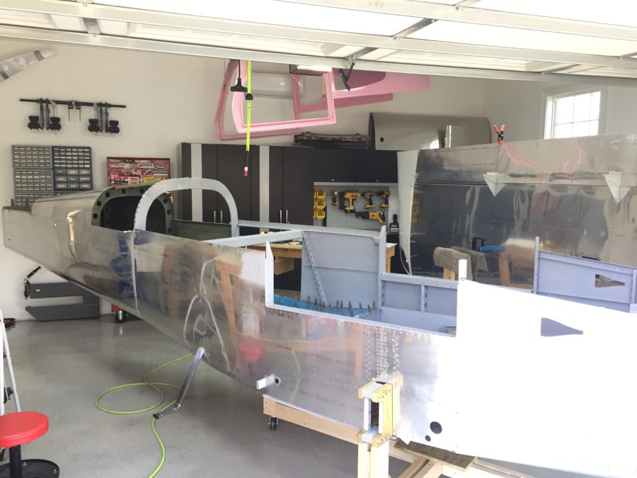
I skipped a major step during the tailcone build sequence by never installing the horizontal and vertical stabilizers onto the tail cone. I didn’t see a point of doing that in the garage just to take it all apart again for storage for years. Now that I’m in the hangar and have the room, no excuses are left. I didn’t build either stabilizer, as the original tail kit owner built them. After looking over them and cleaning them up, I “touched up” a few of the rivets I felt were under squeezed. They aren’t primed on the inside either but even after 10 years of sitting around, they are looking good and corrosion free.

The process went as planned and I spent the better part of one full day getting it all drilled and bolted on. I had purchased the CNC brackets from somewhere to mount the horizontal stab so I didn’t have to make them. I have no clue where I got them from, however, as I bought them on a whim years ago. Either way, they’re nice and you should buy them.

The only hiccup came when working on the elevator trim cable. The original builder had installed the plastic snap bushings the trim cables run through while building the stab. Unfortunately, he put the wrong size bushing in one of the holes that was buried in the spar. The cable wouldn’t pass through. Fortunately the hole was the correct size but man was it a pain in the ass and fingers getting that old one out of there.

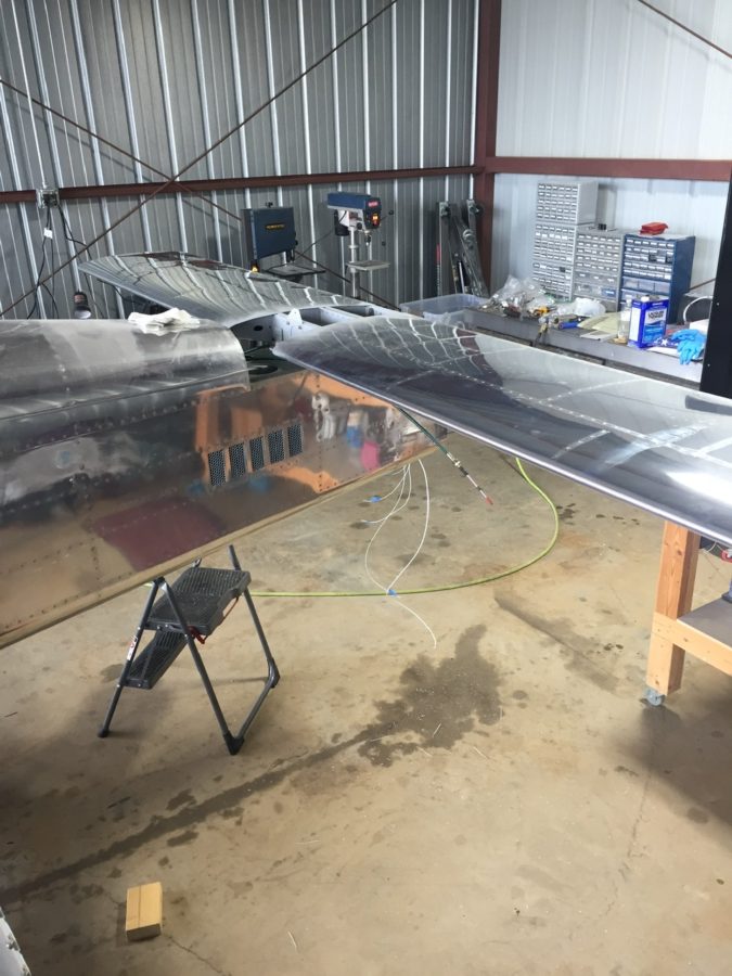
Laura helped me bolt the rudder on next to set the rudder cables up and do some trimming for the rudder trim wires and tail light wires. All easy stuff and its really exciting to see the tail feathers finally get attached.

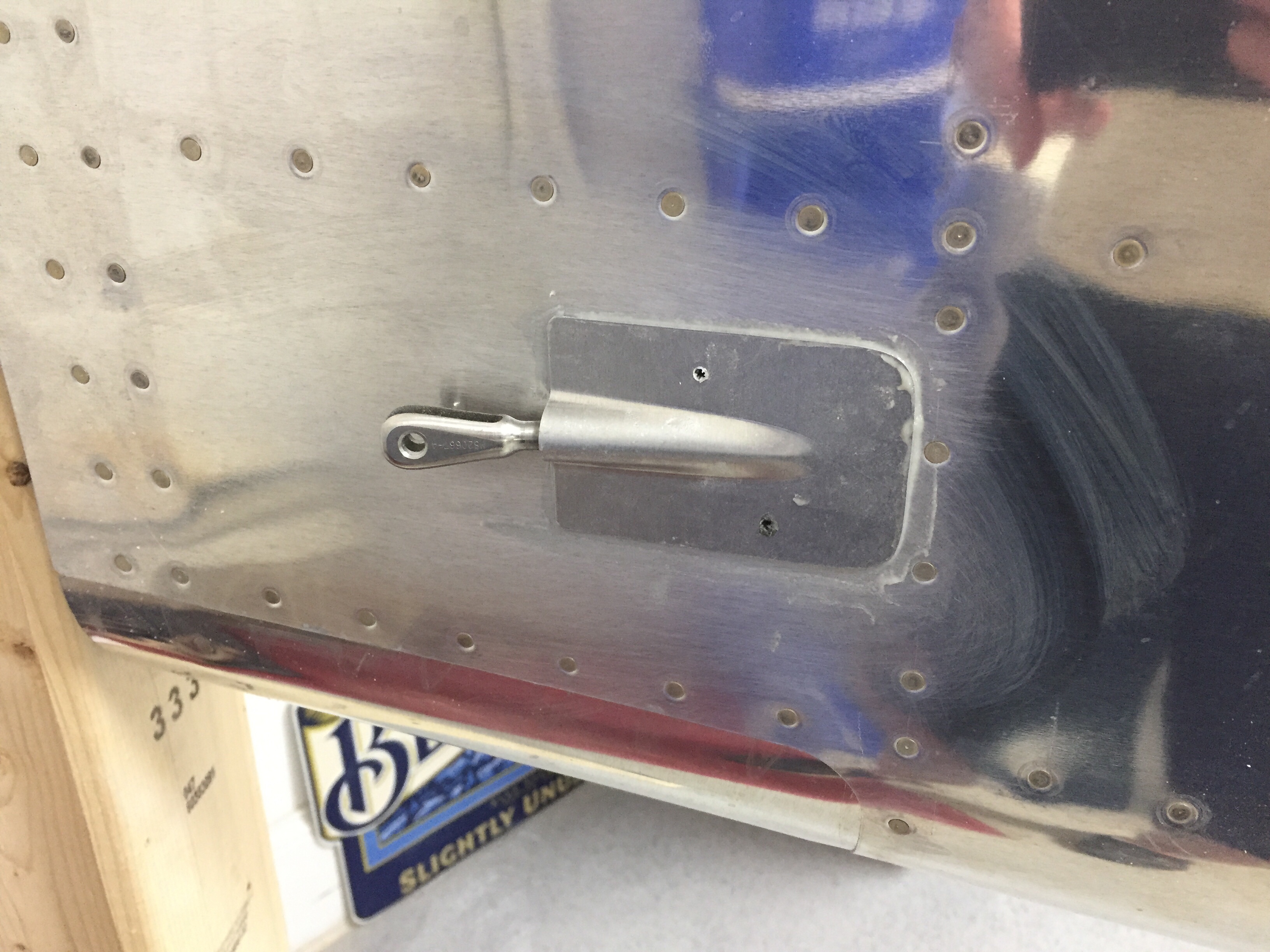
I was able to finally hook up the elevator torque tube after drilling the horns. I was careful to get them lined up accurately and am pretty happy with the end result with the right elevator being lower on the trailing edge by about 1/16″.

I then set out to start the rigging process by centering the stick and adjusting pushrods to get the control surfaces all lined up. It takes quite a bit of stick movement to get the control range established by the plans and I found some interference with a bolt on the aileron rods under the seat pans. I was able to switch the bolt orientation and it cleared right up.

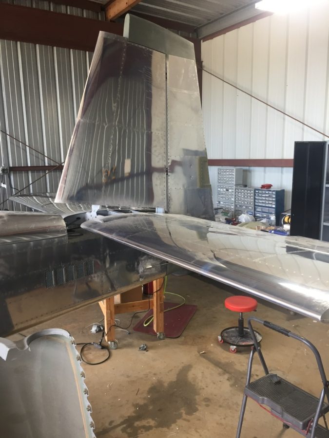
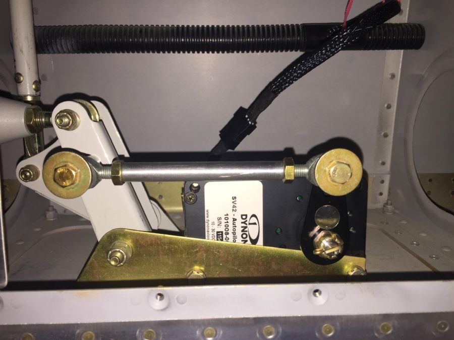
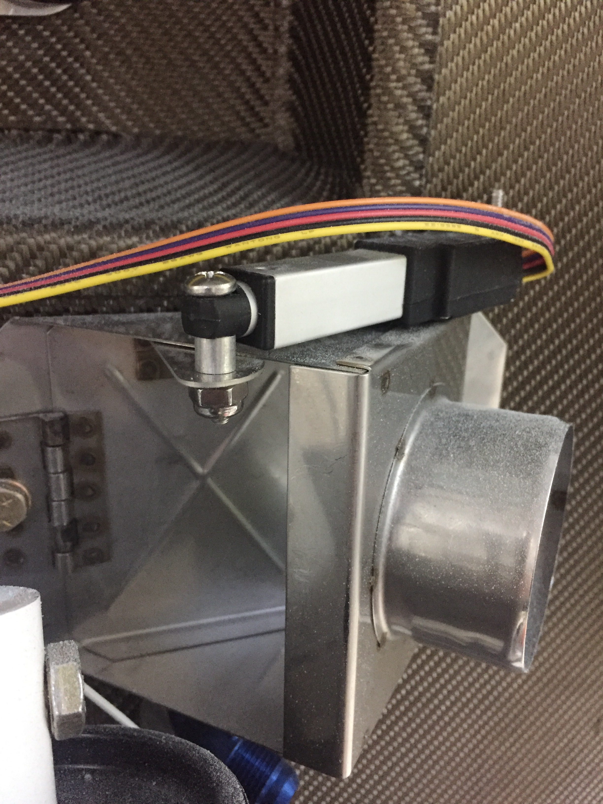
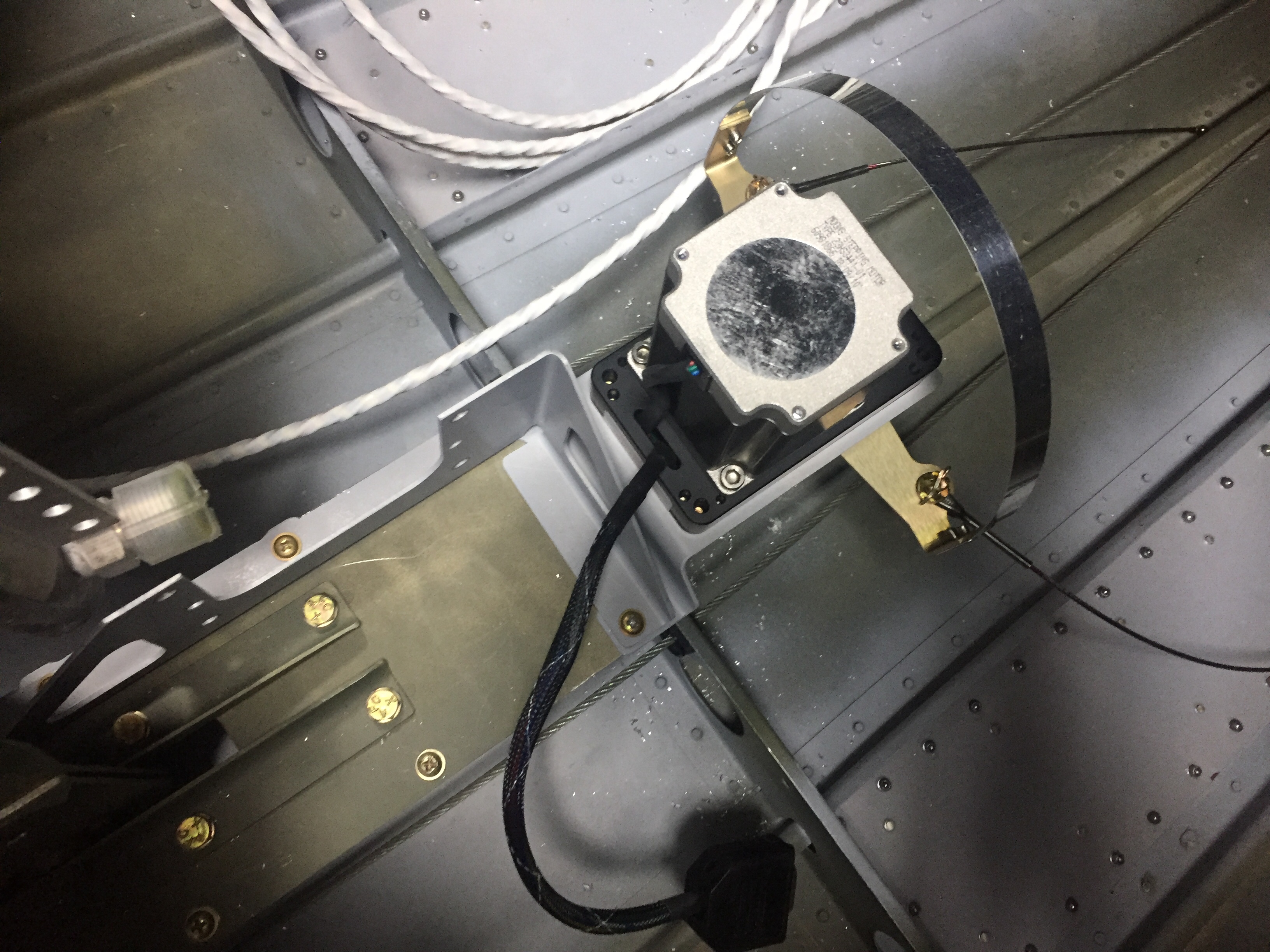
The autopilot roll servo went into the right wing pretty easily as well. I had the mount installed during wing construction, so it was a matter of bolting it in and attaching it to the aileron bell crank. The wiring hooked up quickly since I had already ran the wires and installed a connector.

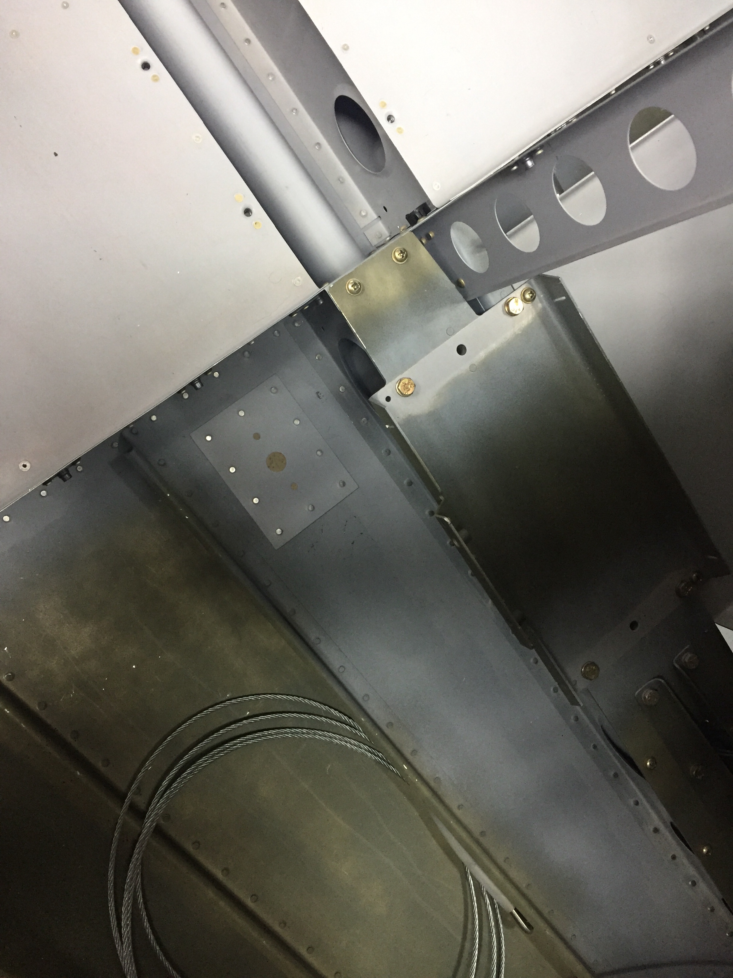
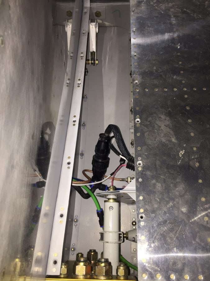
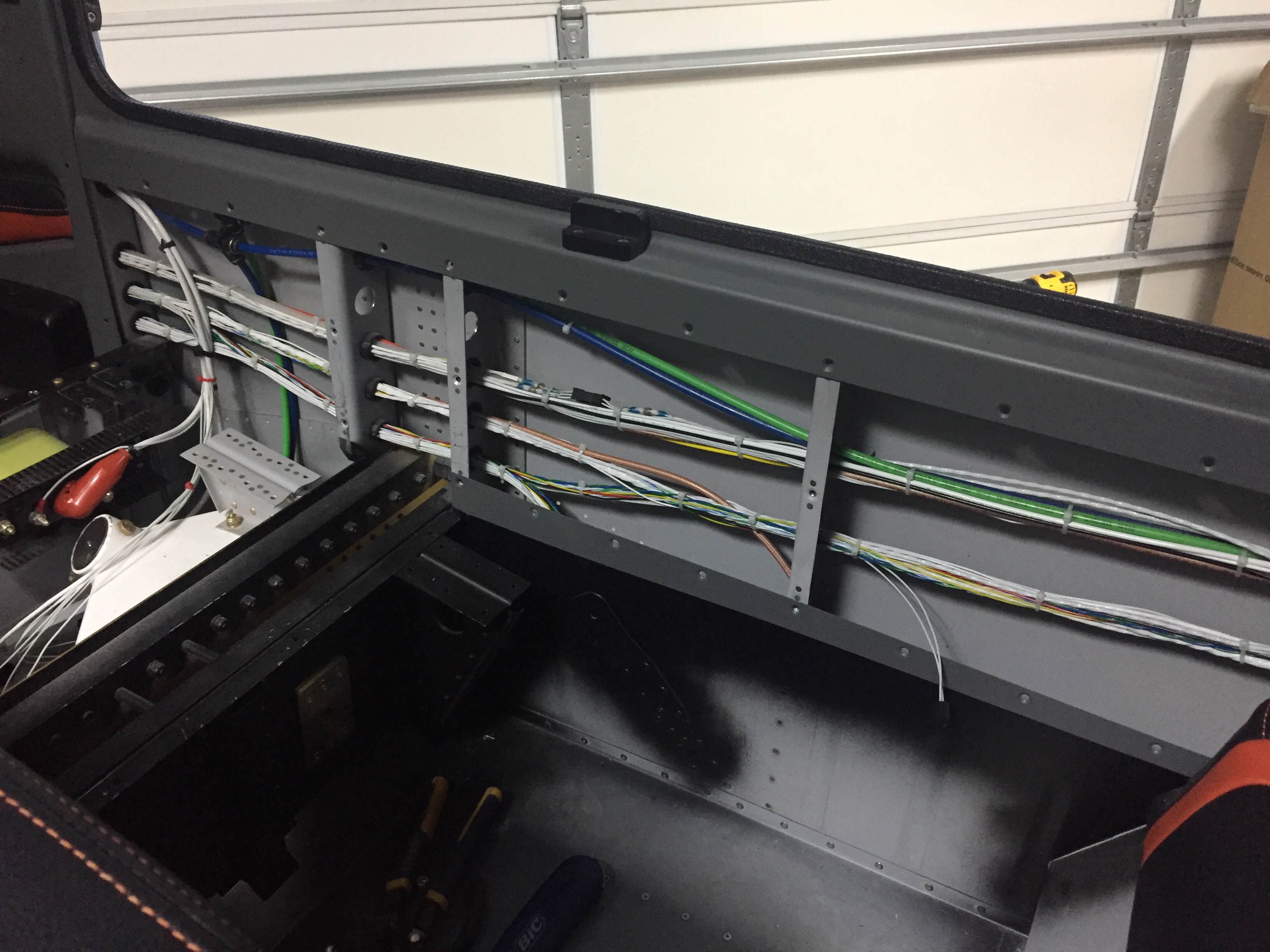
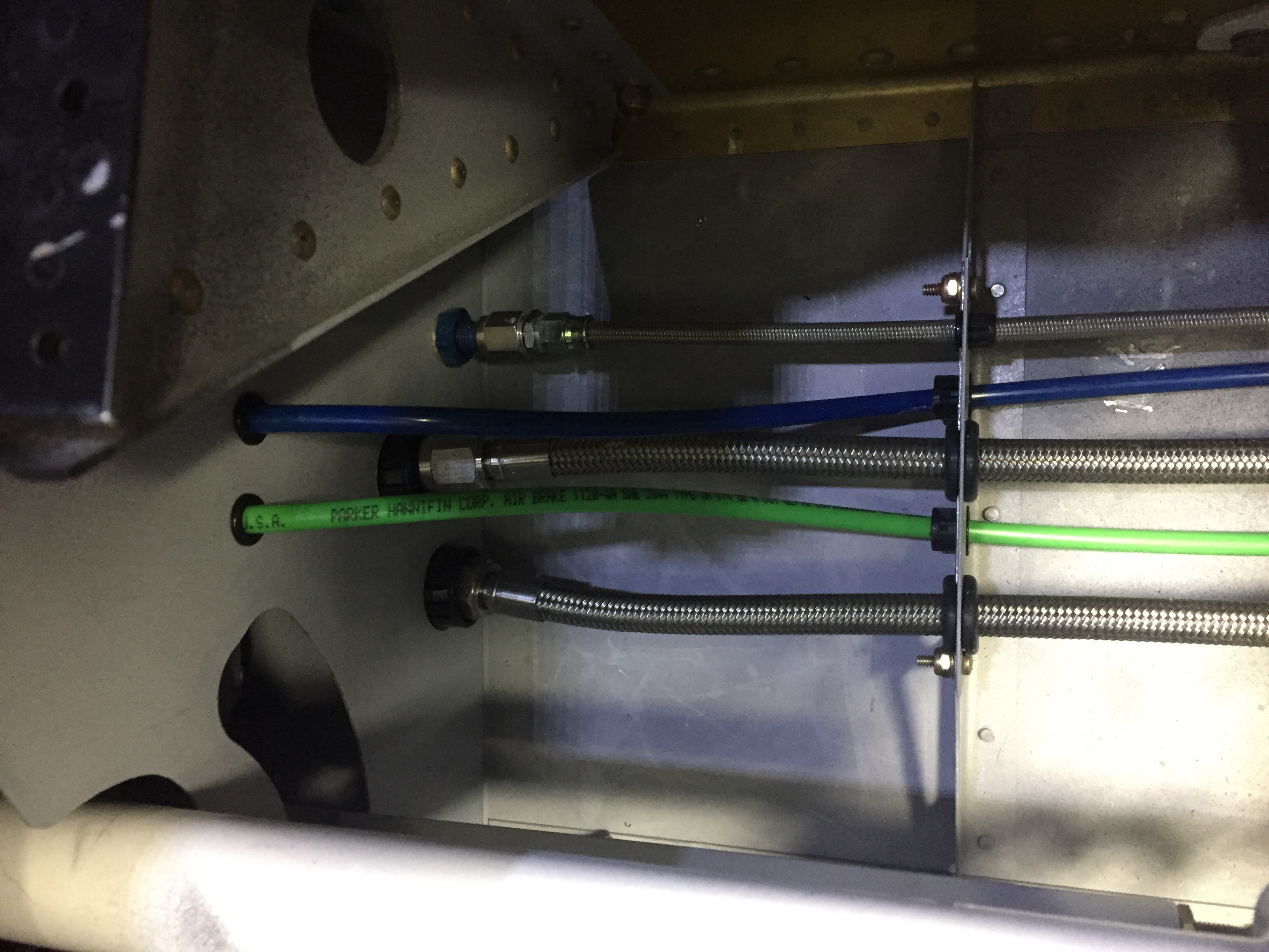
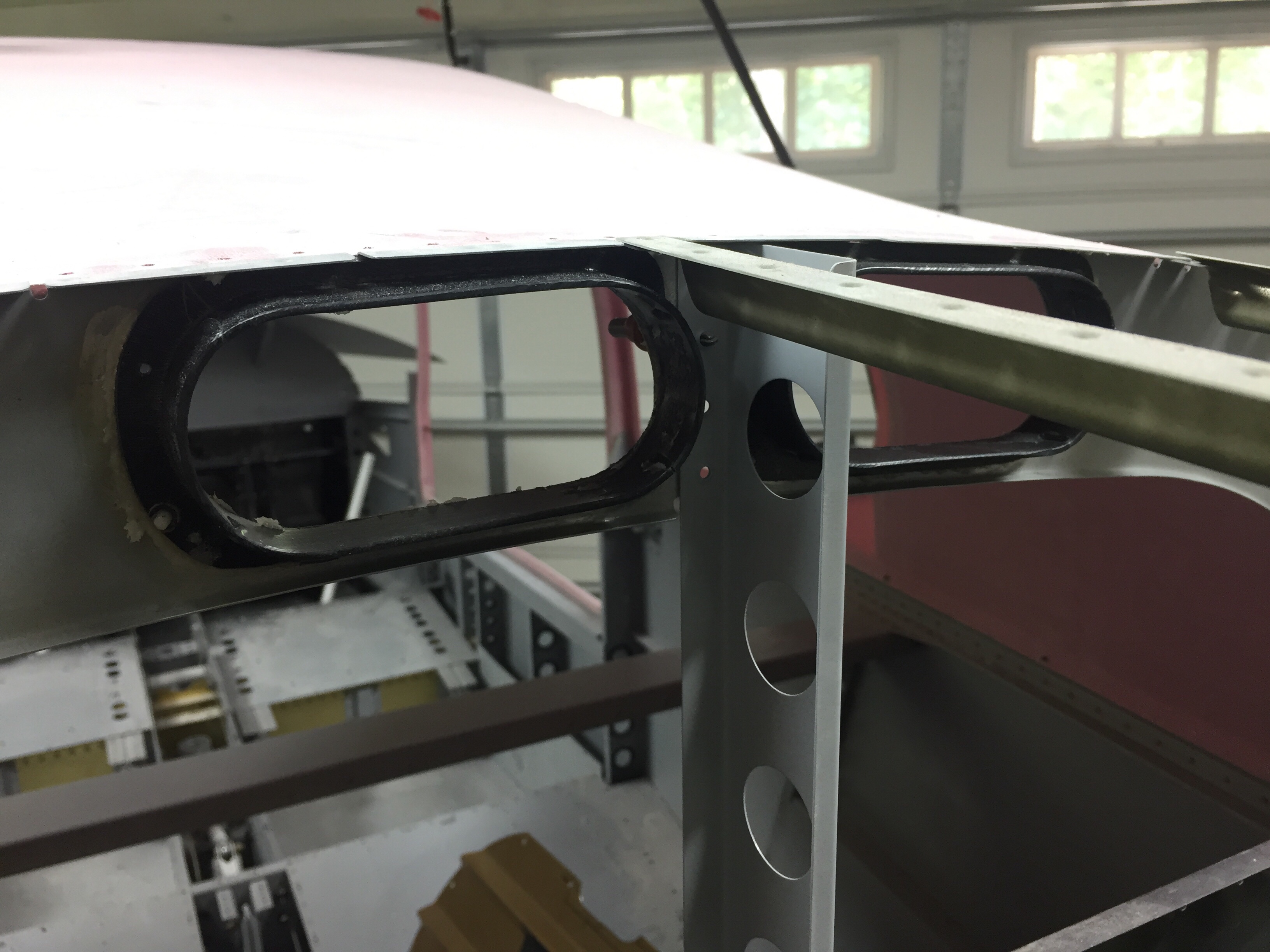
I cleaned up a bit of the wing root area as well, hooking up the CPC connectors, pitot/AOA tubing, and ensured it all cleared the control rods inside. I had planned to mount a bracket holding the CPC and pitot/AOA tubing somehow, but the whole bundle is so stiff, I’m not too concerned with securing it further. It’s also well clear of the torque tube despite the appearance in the picture.

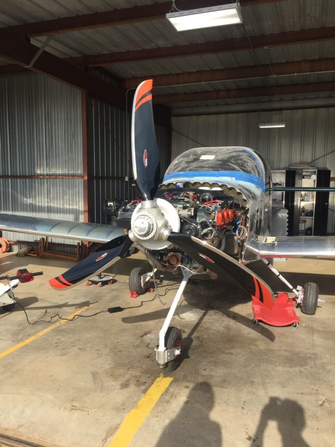
Finally, we had some good light from the sun on the propeller and I couldn’t help but drool over it for a few minutes. The orange over black with the polished leading edges are just too damn cool looking. The scimitar shape is sexy too!

Punching the punch list

There are a lot of little jobs that go along with the big jobs on building a plane.  I’m trying to use my time efficiently while waiting on the engine to knock out a bunch of them.  The first was fixing the arms and servos on the heat ducts up front.  An order to ACS and a few minutes at the band saw and the servos for the heat and oil coolers were attached properly and pots adjusted for full travel.  I also spent an hour trouble shooting a bad pot for the rear heat duct, as I have a switch that allows either the front or rear rheostats to control the servo and the rear rheostat was inop.

I cussed and bled in equal amounts installing the last of the seat rail brackets now the gears are on.  The nuts and bolts are not easy to access at this point, but you have to wait in order to install the gear bolt.  I also put in the last bolt and custom spacer for the GPU plug which helps reinforce the receptacle by attaching it to the seat pan.

I ignorantly forgot to install the transponder antenna before buttoning up the tunnel, so I had to take the center console, tunnel cover, and lower instrument panel off to get down in there.  Of course I burried it near the core of the earth which made access tricky to say the least.  I was able to squeez my hands down there and got it all bolted on with the coax attached.  I knew I had left one fuel line untorqued but couldn’t remember which one so checked all fuel line fittings for proper torque.

The last task in the rear tunnel is to secure the aircon lines which I did with some hose clamps and edge grommet material.  Again, not fun to get to the hardware but it was doable and will rarely if ever be removed.  The lines are now secure and fit nicely in the tunnel, I’m glad I didn’t run them down the side of the fuse.  I also secured the last little sections of the O2 lines in the tunnel.

My ELT antenna placement has been a topic of disagreement on VAF, as I really wanted to avoid mounting it on top of the tail cone.  It’s big, ugly, and ugly.  Mainly, though, it’s ugly.  It’s also essential to my life and the lives of my passengers should the worst happen and we have an accident, so I guess it’s important to do it right.  I debated on doing some reception tests with it mounted internal to the tail cone, but honestly, I just got lazy and decided it really isn’t that ugly.  In the end, I chose to do it the right way and put it on the top of the tail cone.  The cable was secured along a bulkhead and the last of the wiring clean up for the O2 tank / ELT was completed.

I love spending time wiggling back into the tail coffin, I mean cone, so I made a fort with blankets and towels and dove in to attach the OAT sensors to the ADAHRS and finish securing tail cone wiring.  I put the OAT sensors below the access panels underneath the horizontal stab since I had all of my wing wiring complete and for shorter wire runs to the ADAHRS.  Since they have to be calibrated anyway, I’m not too concerned with exhaust from the engine affecting them too much.

The O2 tank was put back in for good and connected to all of the lines.  I also attached the pitch auto pilot servo to the bellcrank and will connect the yaw servo once the tail feathers and rudder cables are rigged at the hangar.  That is the last task in the tail cone and can be completed without having to crawl all the way back there.  It’s going to be motivation in life to keep from getting fat or have a small child that can slide back there for maintenance, it’s a very tight fit with all the extra stuff I put back there.

More zip tie work on the side walls as I cleaned up all of the wire bundles.  I was lazy and didn’t lace them.  If you don’t like that, you go build your own damn airplane!  Lots of zip ties.  Overall I’m happy with the wire runs, I was able to keep coax with mainly data / signal wires and have the high current ones seperated.  I have seen plenty of aircraft with everything bundled together without issues, so I think it’s more important to terminate and ground properly than anything.

The pitot / AoA tubing needs to run across the fuselage from the left wing to the right sidewall, so I put two holes in the tunnel and used free holes from the fuel line anchors to run the blue and green tubing.  The wing is already plumbed, so these lines will connect with those from the wing with two connectors and be done.

Finally, I put the 30 amp Schottky diode on the firewall between the shunt and engine fuse block.  I had this in my electrical design but just in the wrong location.  It provides redundant power input to the engine fuse block only, keeping it from backfeeding the rest of the electrical system.  The power comes in from the emergency engine power switch which comes from the battery to the fuse block.  Big picture, it is a redundancy for the single point of failure of the master contactor or short in the system.  A complete electrical failure or engine stopping SOP will be to turn off the master switch (leaving PFD, MFD, and G5 operating on independent back up batteries) and switch on the emergency engine power switch.  If the battery has any juice at all, it will go only to the engine fuse block.

In Over(my)head

Just when I thought I was nearing the work on the inside, all hell breaks loose.  As I had put masking tape on the overhead console to protect the paint from scratches caused by fitting the headliner base, I wound up setting myself pretty far back by ripping off chunks of paint with the tape.  Now we all know it’s probably not the paint’s fault.  It’s mine.  Why do I do stupid things like not properly prep the surface and not prime?  Seriously.  WTF Tim?  Get your crap together.

Bottom line, I knew as soon as I painted the overhead it was fragile.  The paint had already chipped off a few spots around the metal insert panels and I was concerned that it wouldn’t hold up to normal wear and tear.  I chewed on having a professional painter take it and strip the entire interior but then decided against it, not wanting to give up control.  On the surfaces where I properly prepped and applied the paint, I was very happy with it.  I like the idea of being able to do spot touch ups with a spray can down the road.  All of the interior matches.  All those plus the thought of someone inadvertently sanding through filler while trying to remove the current paint helped me climb in with a razor blade, pile of sand paper, and a neck brace to start working overhead.

After about three hours of work, all the paint was off the overhead and everything had been sanded down with 120 grit.  Even though Aerosport says 320, I found that it wasn’t really marking the surface much, and I want the paint to stick this time!  I took my time around the vents and areas of the cabin top where I knew the paint/primer was strong such as the door frames and switch panel.  As I was removing the paint, I could obviously tell where areas were better than others.  Around the door frames that had been scuffed and near the switch console where I had primed, the paint was a real bear to remove.  That gives me hope I can do it right.

This time, I’ll use tack-free to wipe down the entire surface very well and remove any contaminants (something I didn’t really do before) then use an adhesion promoter while putting the primer on.  I have the fuselage all cleaned out from dust (again) and need to finish the touch ups on the door at the same time.  I’ll also spray the baggage door panel.  I’m not going to jinx myself and say that will finish the interior this time.

Meanwhile, my first two very expensive boxes of avionics have arrived!  The lesser of the two from Tosten had my two stick grips in it which led to lots of button pushing, trigger pulling, couch flying while making airplane, gun, and missile noises!  I’ll try to get a video sometime.

The big box was from Advanced Flight Systems as a prelude to the full panel being shipped in a week or two.

They were nice enough to ship me some advance components and harnesses such as the ADAHRS, servos, and EMS among a few other things.  I first ran the autopilot servo wire harnesses and already appreciate the value of having AFS wire the majority of the avionics.  I pulled 21 wires in about 10 minutes that are already pinned on one end.  That task alone would have taken a day to measure, cut, label, pull, and pin all of that.  Once the servos are in place, I’ll use the supplied pins to finish the connections.  I also pulled the SV network cable that will run to the ADAHRS in the tail cone.  I essential tripled the amount of wiring in the aircraft in less than 30 minutes!

My yaw damper mount arrived from Van’s so I set about installing the pitch servo mount and yaw servo mount back in the tail cone.  Woof, what a pain in the ass to get to at this point.  Future builders, buy this stuff early and put it in when building the tail cone!  By sheer luck or divine intervention, the AC condenser clears the pitch AP servo by about 1/8″.  I really lucked out, because I had no idea how it would all fit when I redid the AC.

I do not enjoy laying in the tail cone so I made a list of everything needed to be done for the next and final time during the build getting back there.  I decided to remove the O2 tank to make more room and was able to mount the ADAHRS tray fairly easily.  I managed to get it within .75 degrees on all axis by sheer luck, again, but I’ll take it.  I routed all the tubing and installed the pins on the wiring to hook the splitter up to the harness from the front.  I took the time to lace all the wiring and installed a few grommets back there.  It all cleaned up very nicely in the end and I’ll just need to shimmy back again to hook the rudder cables up to the yaw servo once the tail is installed.

Full of hot air

Anytime you have to cut a huge hole in the side of an airplane, your palms should start sweating. Mine sure did, especially since I’ve already cut two holes in the bottom of my airplane. Since the condenser duct system was cured and ready for install, I marked the exhaust cutout area got the Dremel out.

I had already ordered some auto grille material that provides some debris protection while allowing good air flow from the fan. It’s very similar to what Beechcraft is using on the Bonanza. I spray painted the plenums to minimize cosmetic issues once the plane is all finished. I used flox to epoxy the grille and duct onto the skin, making sure the grille didn’t have any extra epoxy on it. Once that was all sorted, I got the fan mounting plate hung via angle pieces to the AC equipment tray. The fan bolts to the mounting plate which is sealed to the plenum with a gasket made of neoprene, so the fan is replaceable and will also allow me to block off the fan during final paint.

Next is the condenser to fan plenum which I sealed to the condenser with silicone. This slides over the fan frame and is sealed with a small bead of silicone around the seam, keeping the air moving where it should. The condenser also hangs from the equipment tray and has a flat stock support bar that keeps it from swinging. Once it was all together, it was very stable and will still allow a very tight, but passable cavity for me to crawl into the tail cone.

The clearance between the condenser and the pitch torque tube and pitch auto pilot servo is tight but it does all fit with no interference. With all of the equipment and exhaust ducting in place, I need to supply a fresh air source. The stock setup used one of the ducts you can see in the floor of the tail cone above, but they scooped air out of the exhaust heavy airstream. Again, like factory setups, I decided to have a vent on the opposite side of the tail cone with some small louvers just forward of the horizontal stabilizer. If any moisture does come in, it has an easy way out around the tail tie down and won’t affect electronics either.

I kind of wish I had put louvers such as these on the exhaust side, but they’d be pretty easy to add later if needed, so I’ll add them after flying if I have any issues. The same grille material was epoxied in using a flow mixture that was used for the exhaust grille and plenum.

On the cabin side of the system, I cut the holes for the supply ducts into the baggage bulkhead and epoxied the duct shells into place. These line up into the Aerosport overhead console and the return air for the evaporator will go through the bulkhead itself as I am reusing the original owner’s setup and will have a faux trim covering the bulkhead to dress it up a bit.

Since I had taken everything else apart, I tore into the cabin fan box as well just to see what it looked like. It’s a pretty simple system but seems to work well. One thing I did notice was the fan speed control having four speeds. The wiring was to the low, medium, and high speeds with the max being unused. I decided to slide all three to the right so the speeds are med, high, and max which should give even more airflow out of the vents and through the cabin.

I took some extra time to silicone seal the assembly back together and made sure it was nearly air tight once complete again in the effort to increase efficiency. The equipment tray already had the mounting provided, so it was bolted back in and I went to work putting the flexible duct to the bulkhead supply duct headers.

I’m ordering some thin worm clamps to clamp the ducting to the headers since the zip ties don’t really create a good seal.

After all said and done, this was a lot of work but it wasn’t terrible work. I’m very optimistic that the bones of the system will now work even better to provide cool air to the cabin and minimize the amount of attention the system will need over time. I still need to run the electrical and refrigerant hoses, which I’ll cover in a later post.

On a side note, I am still knocking little jobs off of the list such as the rudder cable fairings on the tail cone and a few other mundane tasks. Little bites at a time equal eating an elephant. Although you shouldn’t eat an elephant because you’d be a terrible person.

I also took out the stock intake and exhaust vents for the air conditioning and patched them using the original skin and backer plates made from the trim kit. I’ve finished that up by putting some filler in the cracks and smoothing it all out. It’s not perfect, but good enough for the bottom of the fuselage. If you’re judging my plane that much, you better have a rag and cleaner to wipe it down while you’re under there!

So I changed my mind, cool it.

I’ve been doing a lot of research and discussion with folks who have installed air conditioners, especially the Flightline setup like mine. The general consensus is that it’s marginally effective at best. My standards aren’t extremely high, as the AC in the Diamond we fly just takes the edge off but doesn’t really cool like a car would. Others with the Flightline system have added a second condenser and one or two have routed the intake from the bottom to the side skin to avoid the exhaust mixed heated air. As my original commitment to John at Flightline was to design a side intake and exhaust, I decided to dive in and redesign pretty much the whole dang thing.

First, an overview of the setup. An intake on the bottom tail skin catches air and directs it through 6″ flex duct up and 90 degrees forward where it turns 180 degrees and goes through a 12′ square condenser. A 12″ puller fan helps air flow volume so it doesn’t rely solely on ram air pressure. Then, it heads back into a 6″ flex duct, makes another sharp 90 degree corner and exits out the bottom skin. It’s a lot of direction changing and restricting of the air.

I began by taking everything apart and checking out how it was all pieced together. The first thing I noticed was the mounting plate for the fan actually covered a 1/5 or so surface area of the condenser. Additionally, the system didn’t use basic air velocity and volume principles, so it was constantly going from small to large volume spaces with many restrictions.

My goal was to facilitate air flow through the shortest path with the least resistance, thereby providing more efficient flow and better heat exchange in the condenser. I studied several factory AC setups such as the Cirrus, Bonanza, and M350 and noticed no ducting on the intake and direct exhaust from the condenser through the skin. The condensers were also significantly larger in surface area. So the new design would be to pull ambient air from the tail cone through a larger condenser via the same fan and exhaust it through the side skin within the shortest path possible. The ambient air is provided through an louvered intake near the horizontal stabilizer.

So, I bought a 16″ x 12″ condenser and set about molding a plenum from the condenser to the fan. If I had a vacuum table, this would have been perfect to keep the mold to share with others, but unfortunately I had to lay up fiberglass and the molds were trash.

The layup came out very nicely despite destroying the mold and was a perfect fit around the fan casing. A simple bead of silicone should seal it up nicely when installed.

Next was to do a mold from the fan to the skin for the exhaust. I figured up the square inches of the fan and worked within the stringers to maximize the opening area while keeping it just under the square inches of the fan. My thought on this is using the Bernoulli principle and having the smallest (relative to the entire air path) opening creating the highest velocity at the skin. This will in theory help the exhaust penetrate the boundary layer air around the fuselage, which has also been a concern from others.

I used the same fan mounting plate since it’s no longer restricting air flow. The exhaust plenum as a lip molded in to use as a mounting surface on the skin. The weight of the setup will be supported from the stock tray so the plenums aren’t load bearing.

I put it all together and hooked up the fan to check it out. There is significantly more air flow going through and I’m cautiously optimistic that this will create a much better performing system.

Next up will be mounting it all in the airframe and cutting the skin.

Staying in the lines

Throughout this progress, I’ve been finishing up the brake lines.  I ordered extra line for the run from the firewall to the gear legs and got them all fabricated.  The lines weren’t hard to make, but it was a bit tedious.  I am happy with the end result, however, and think that it will provide many years of great performance without having to worry about replacing tubes.  I do need to get some spiral line wrap to prevent chafing and that will allow the lines to be a bit better secured.  Mark Ciglia put his parking break valve in place of the firewall connections, which I’m mad I didn’t think about.  It makes it a bit cleaner and eliminates one extra set of lines, but oh well.  It’d cost more now to redo it.  Note to other builders!

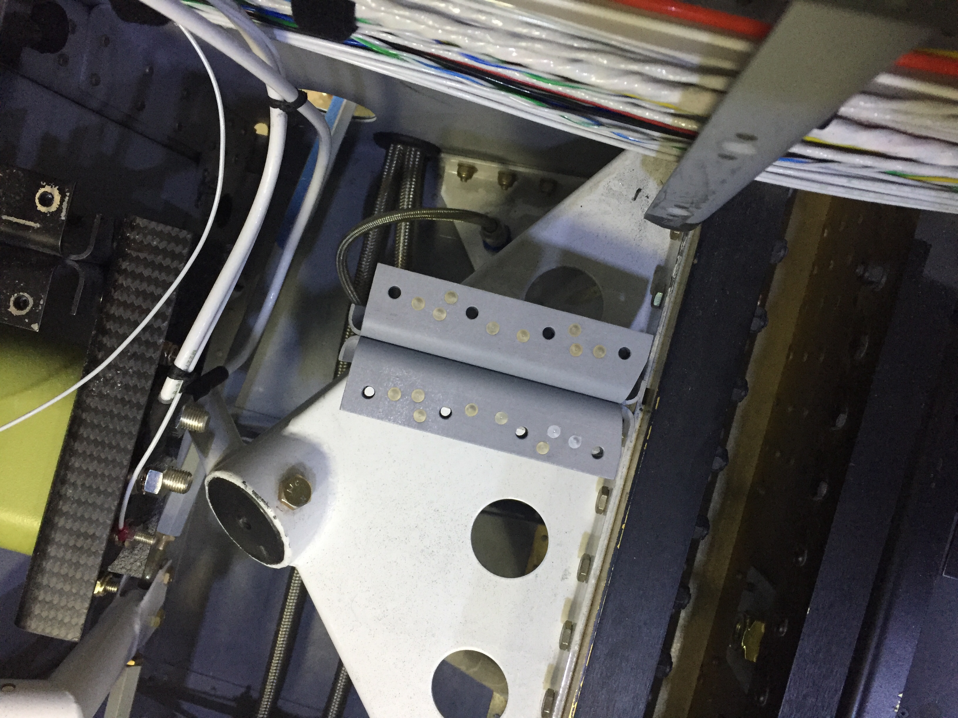
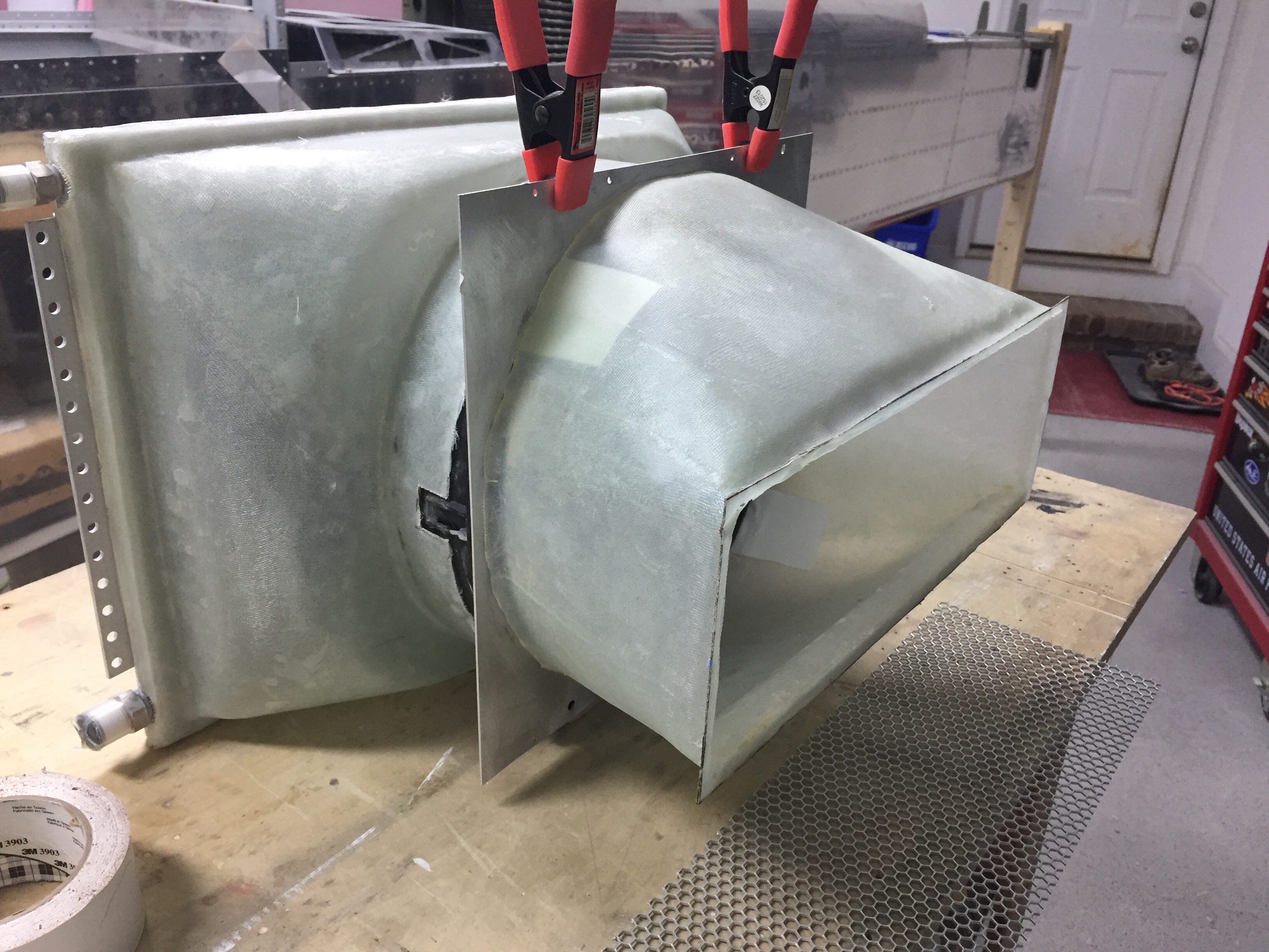
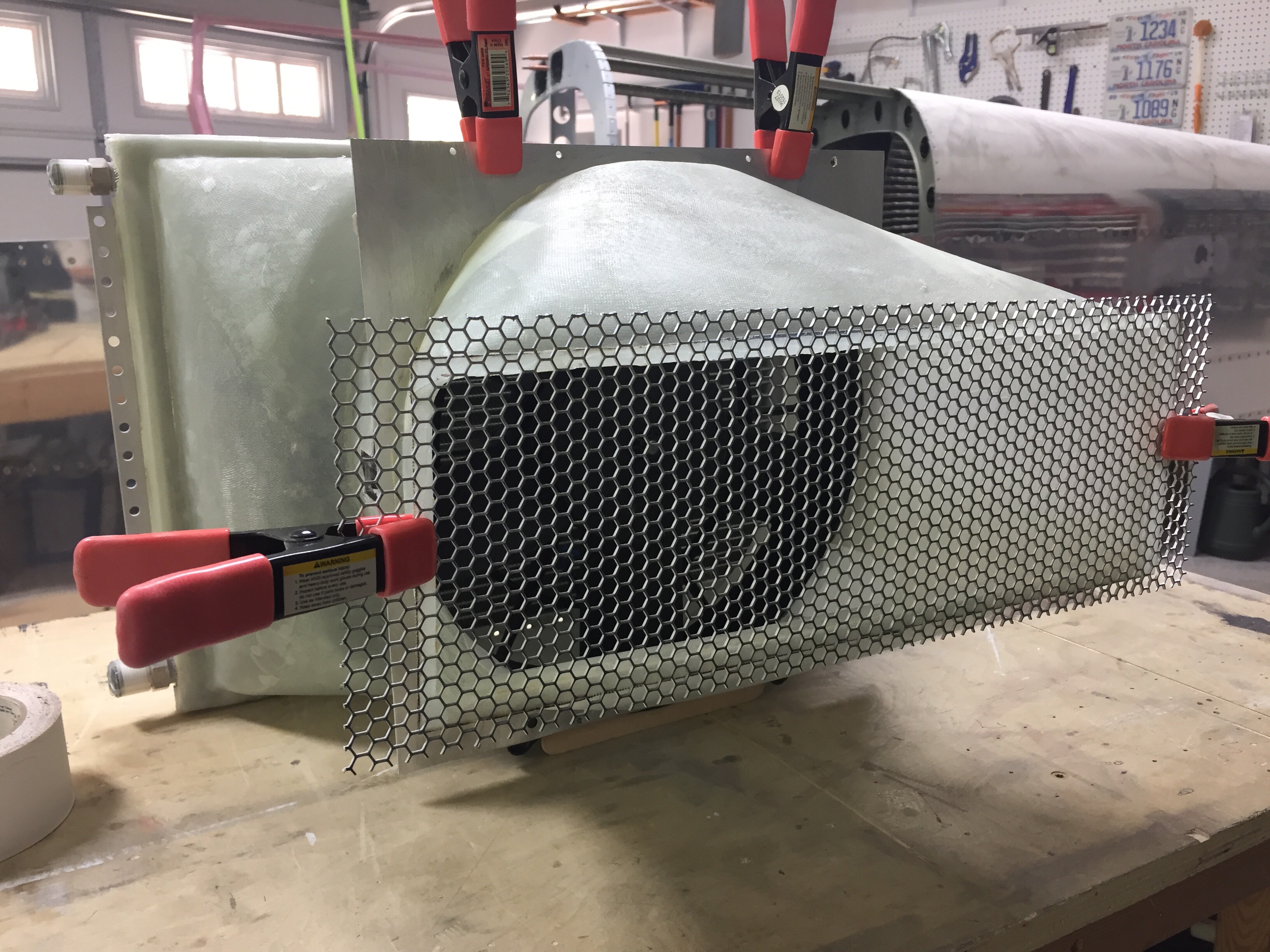
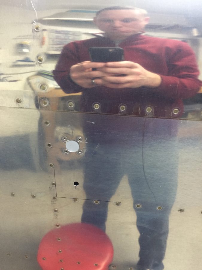
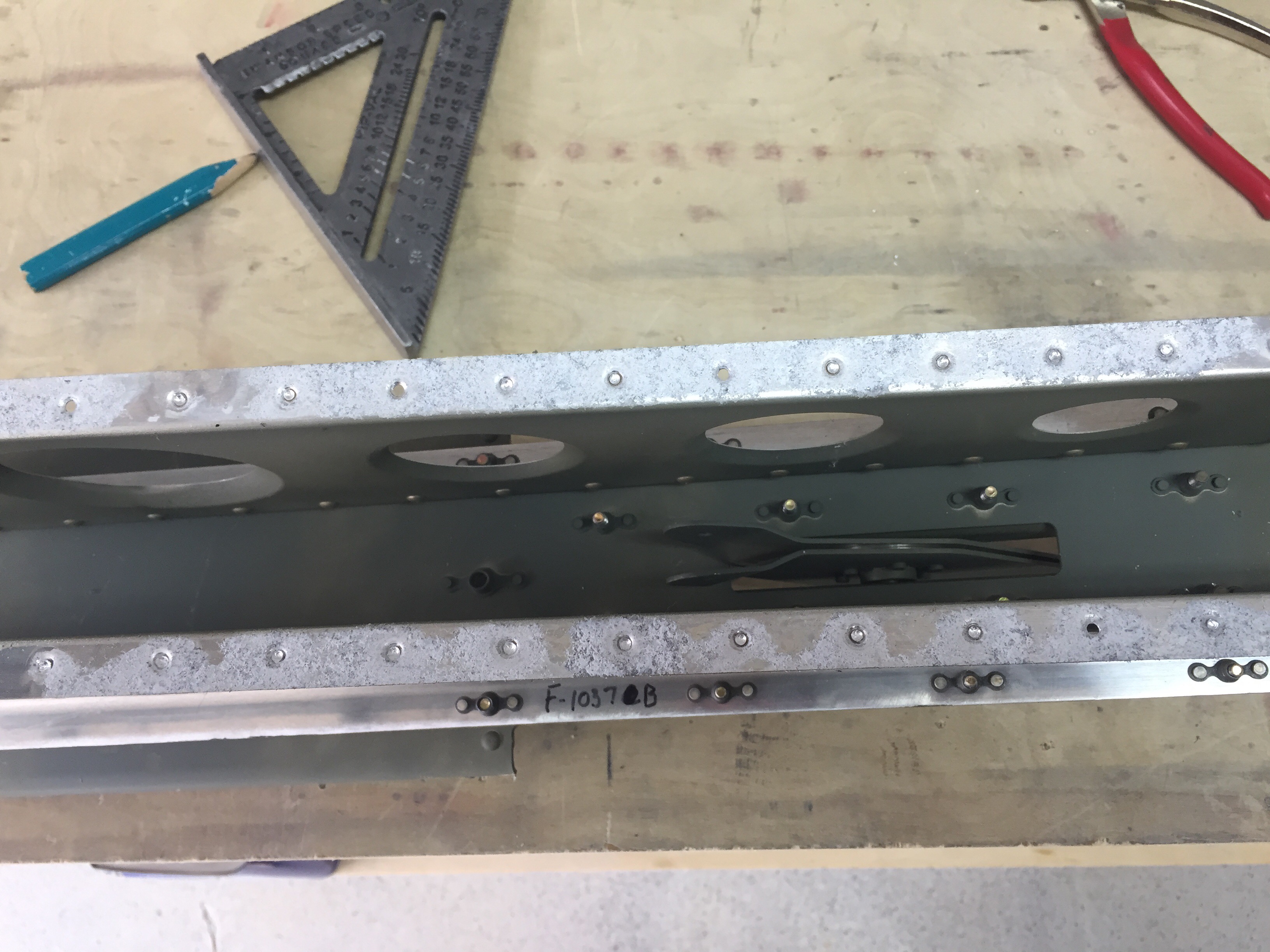
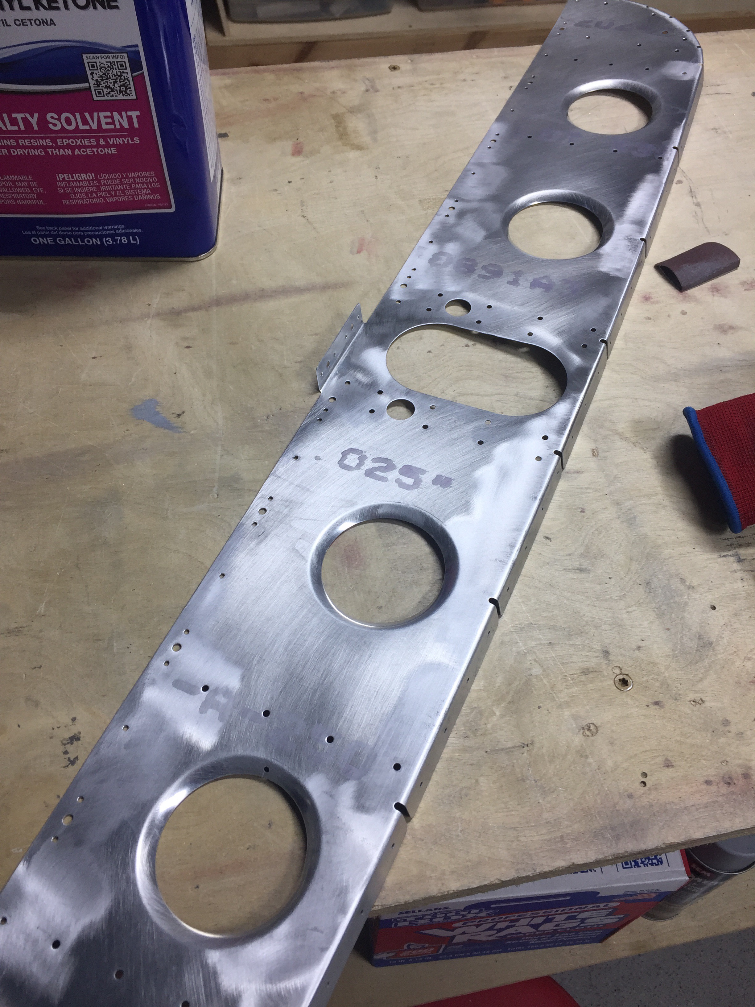
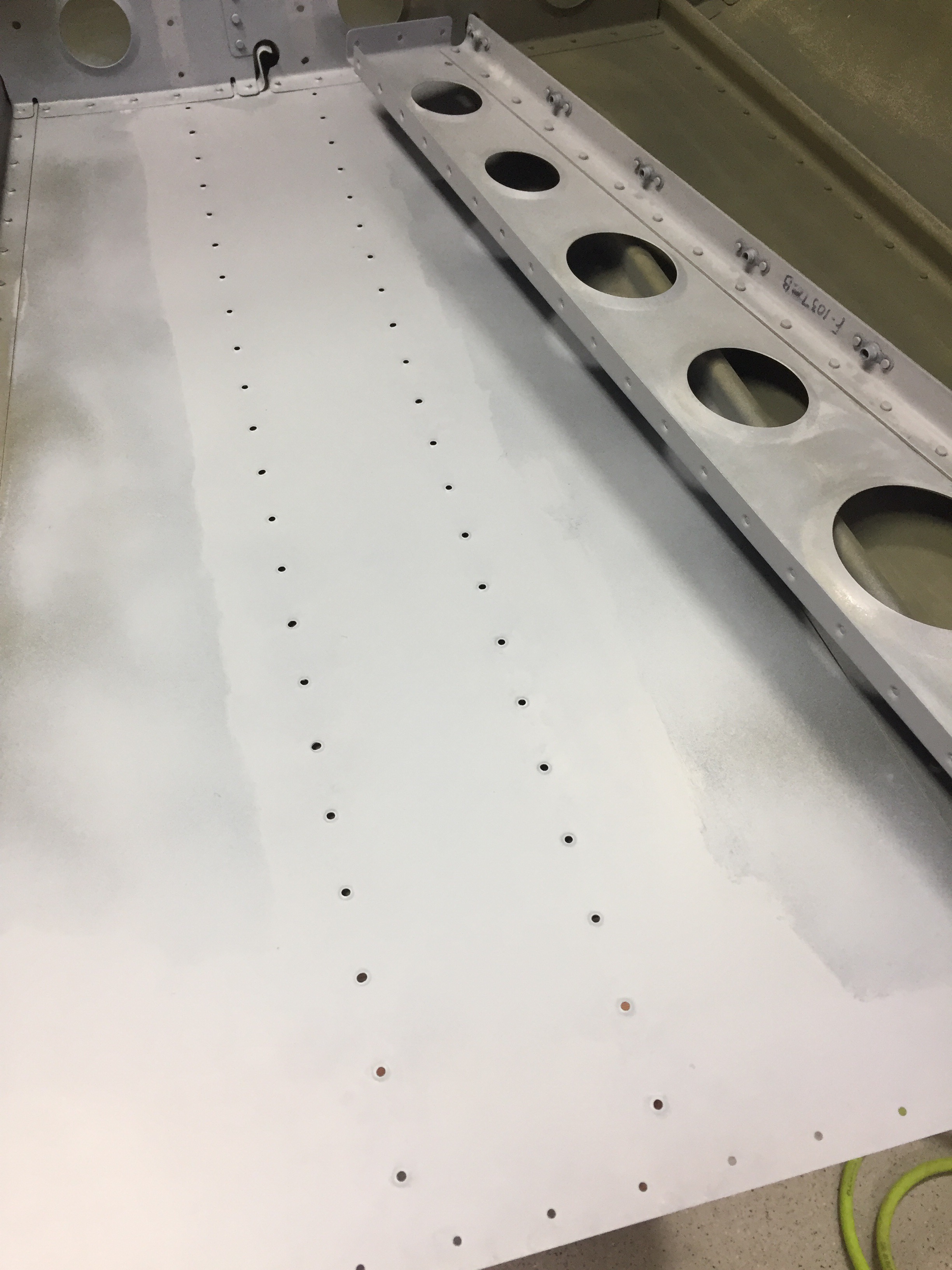
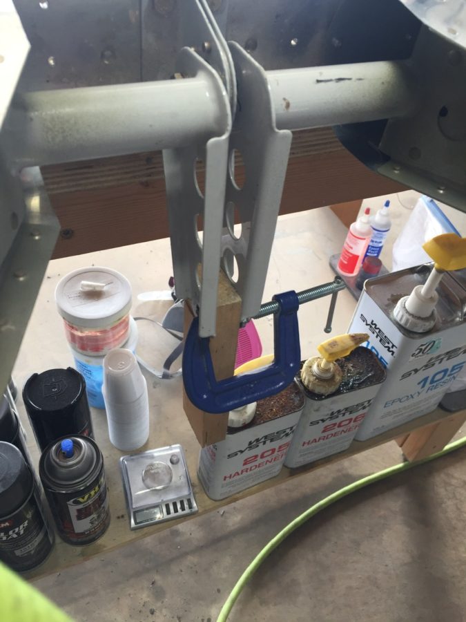
I also knocked out a few little projects, one being making new elevator trim bracket panels.  I had the beefed up fittings sitting in the parts bin and finally ordered the new access panels.  After countersinking and priming, the parts are ready to roll and comply with a SB from Van’s from many years ago.  This is a common upgrade and an easy one at that.

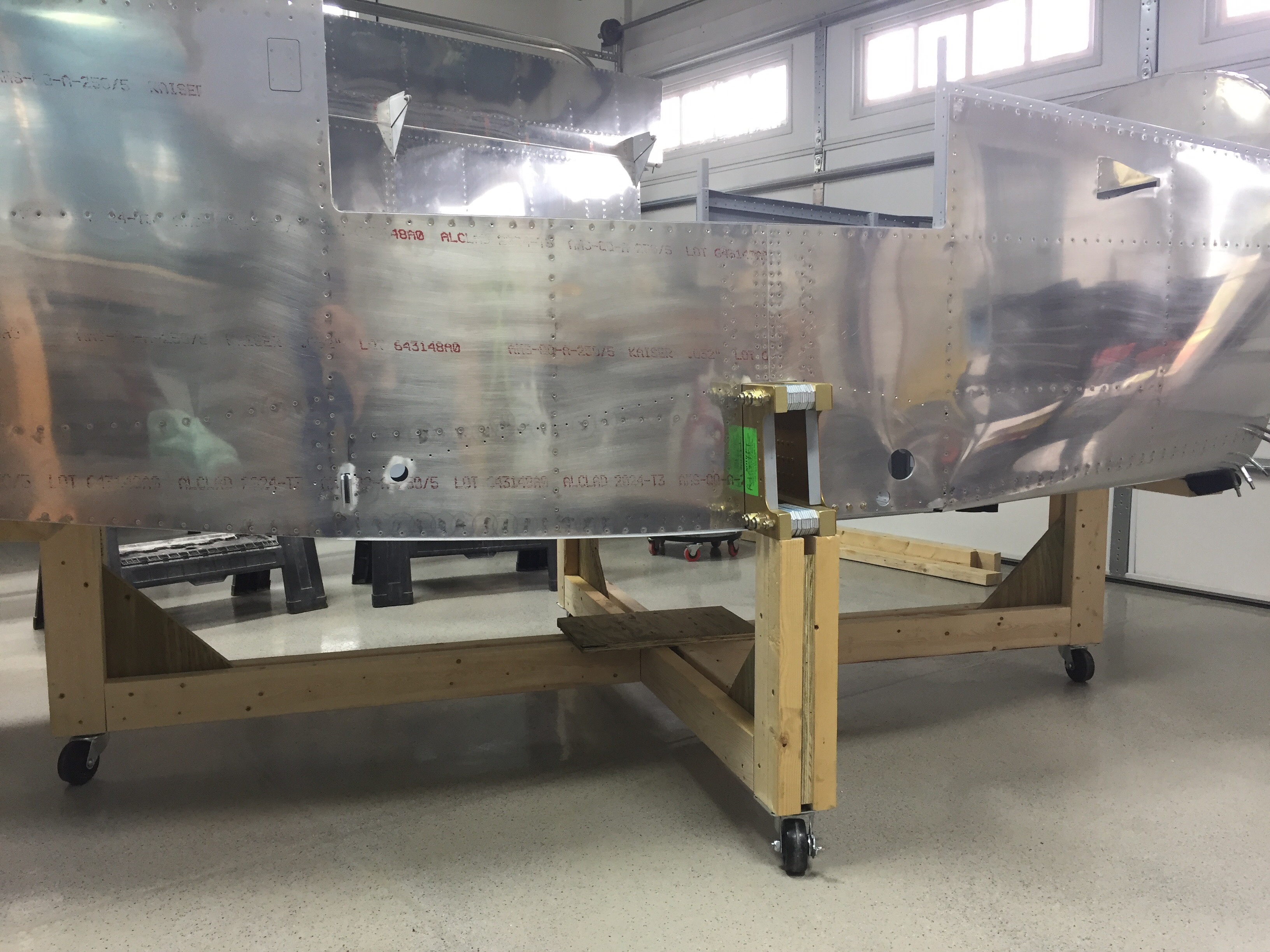
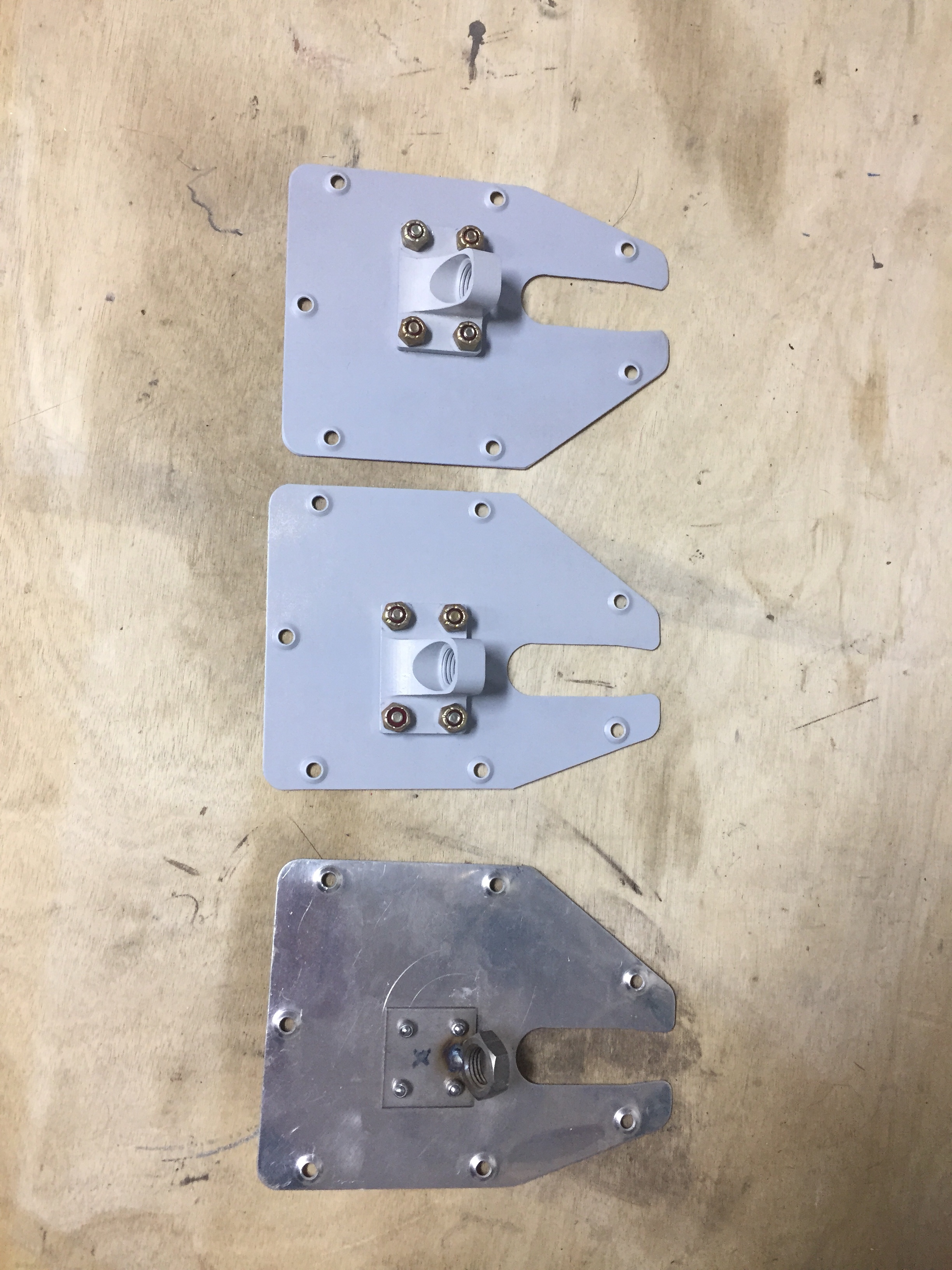
Another little project wasn’t so little.  I saved up a few tasks that needed to be completed inside the tail cone for one evening so I would only be crawling back there once (this time).  The first was to support the tail better.  I used two 1×4’s to bolt to the horizontal stabilizer mounts and put a caster on the bottom.  While the fuselage cradle has been great, the rear support isn’t far enough back to support my weight so far aft without something heavy like an engine hanging off the front.  So this was an easy fix and doesn’t take any room up in the shop.  It’s still very easy to roll around and reposition as needed.

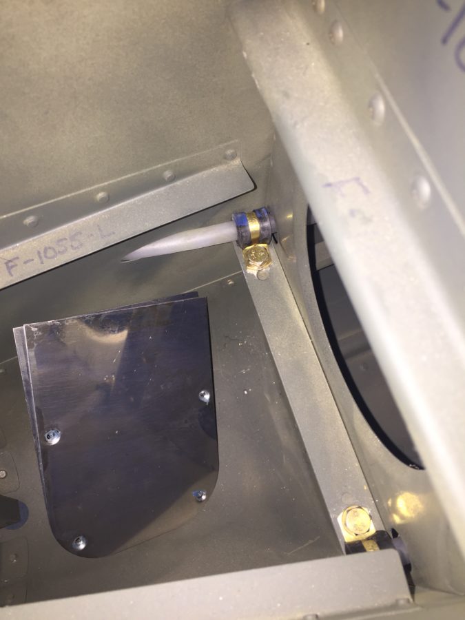
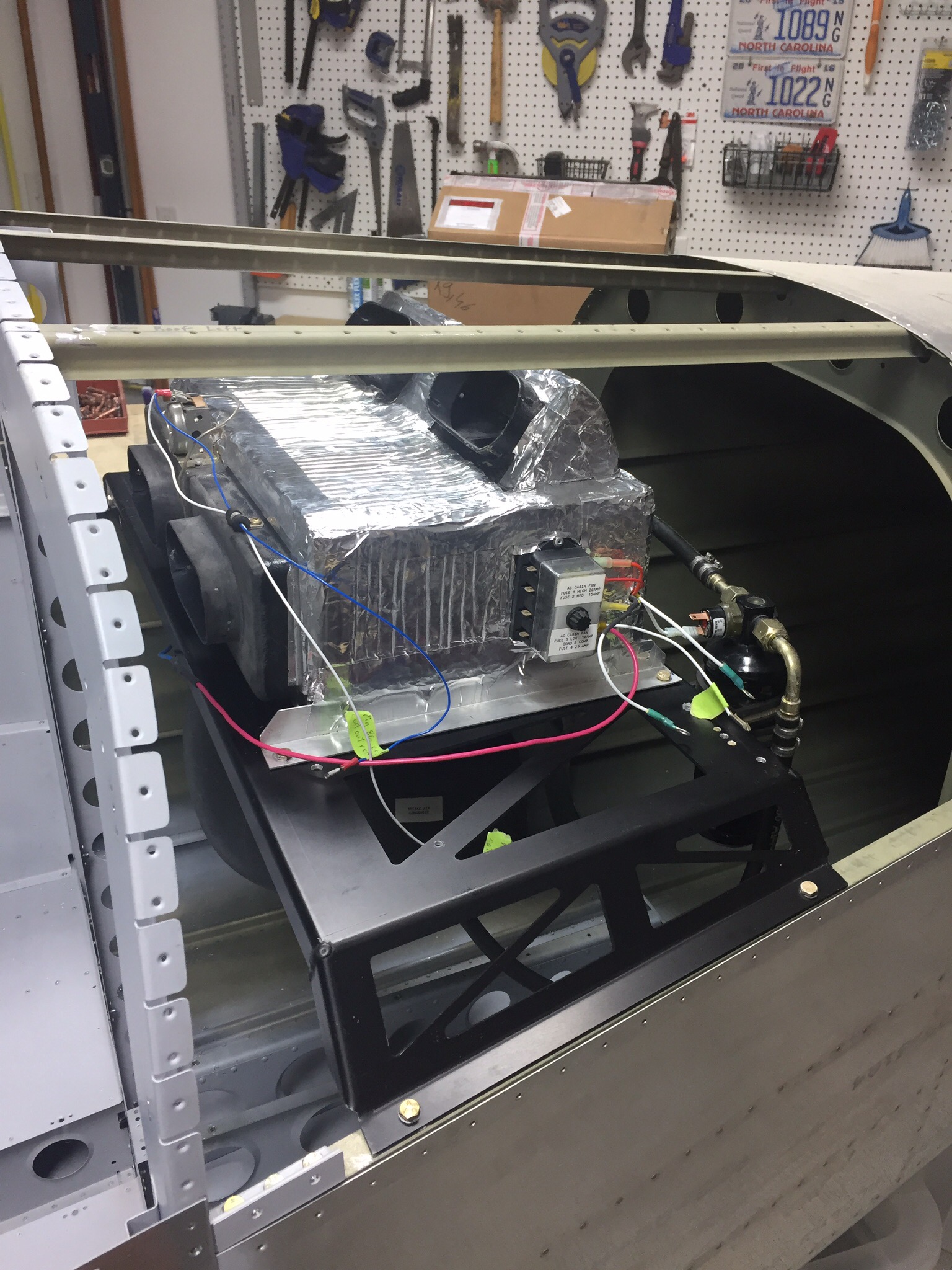
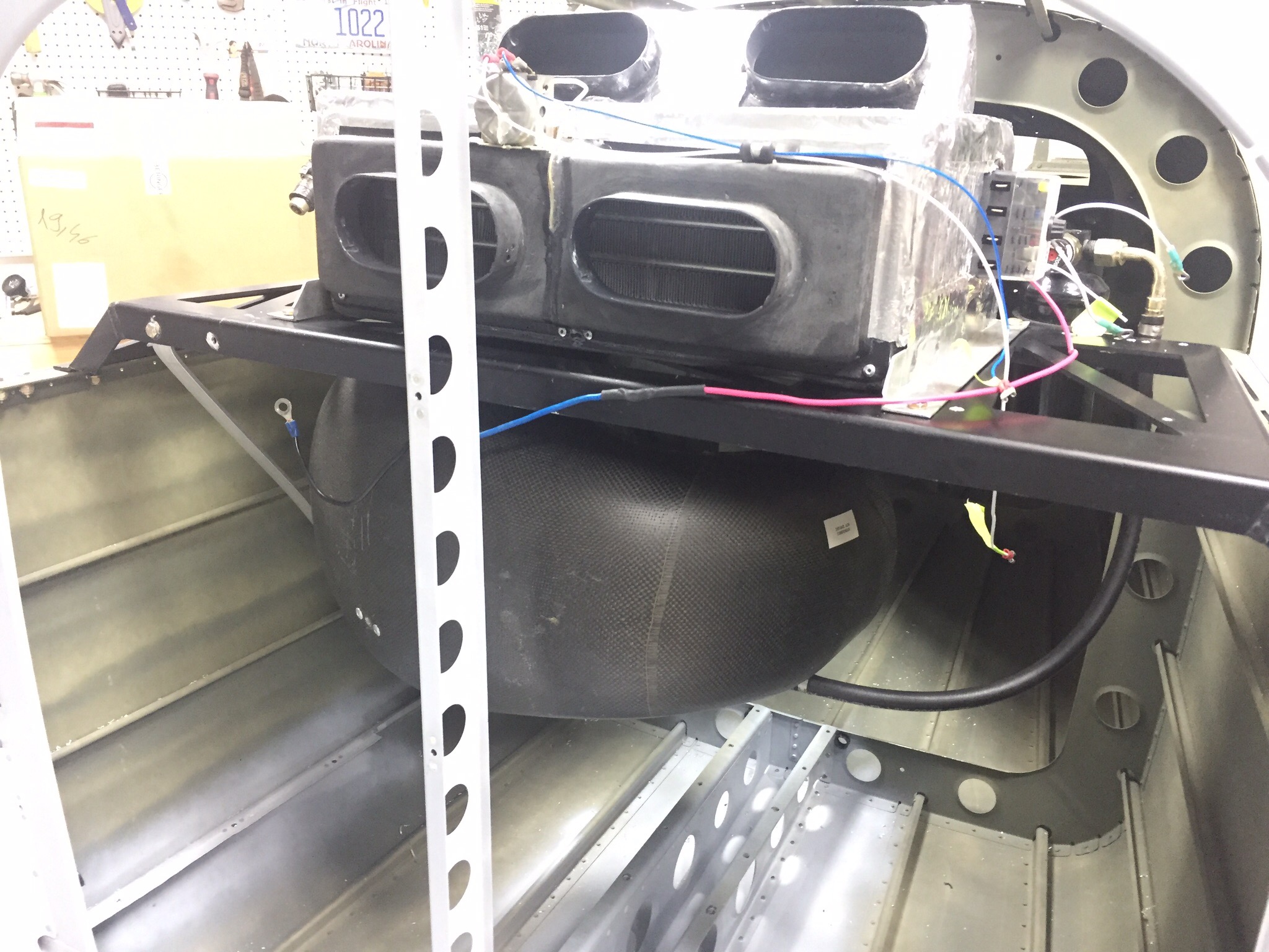
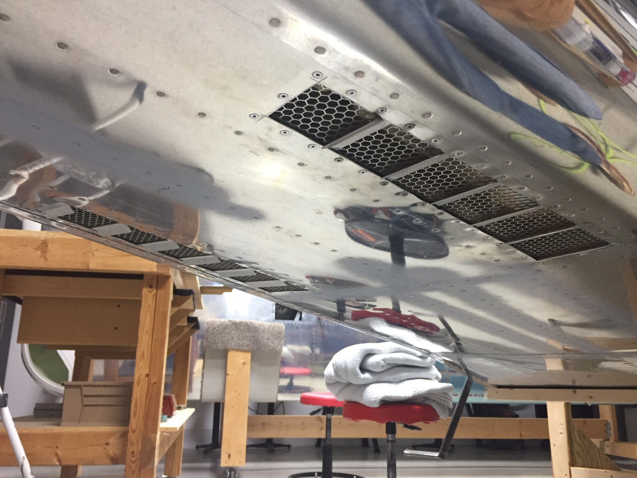
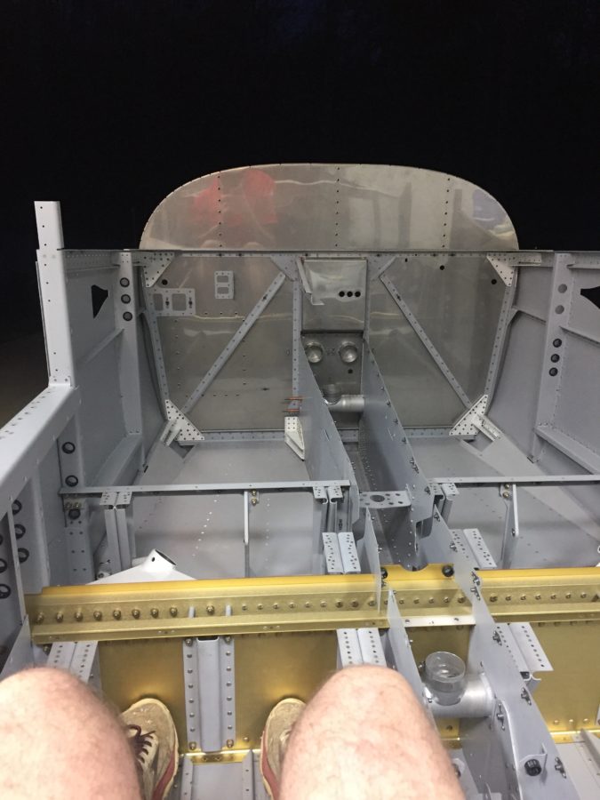
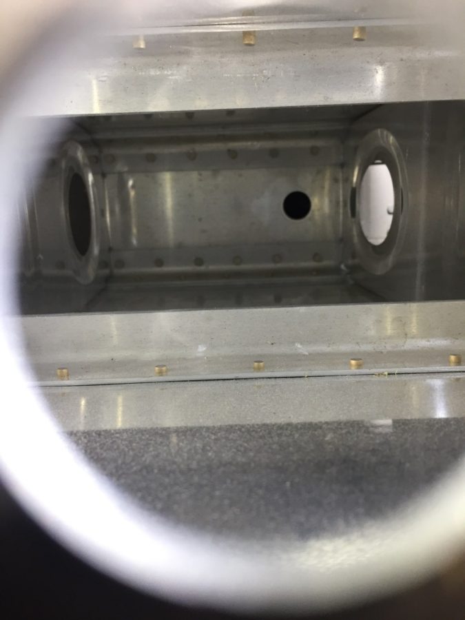
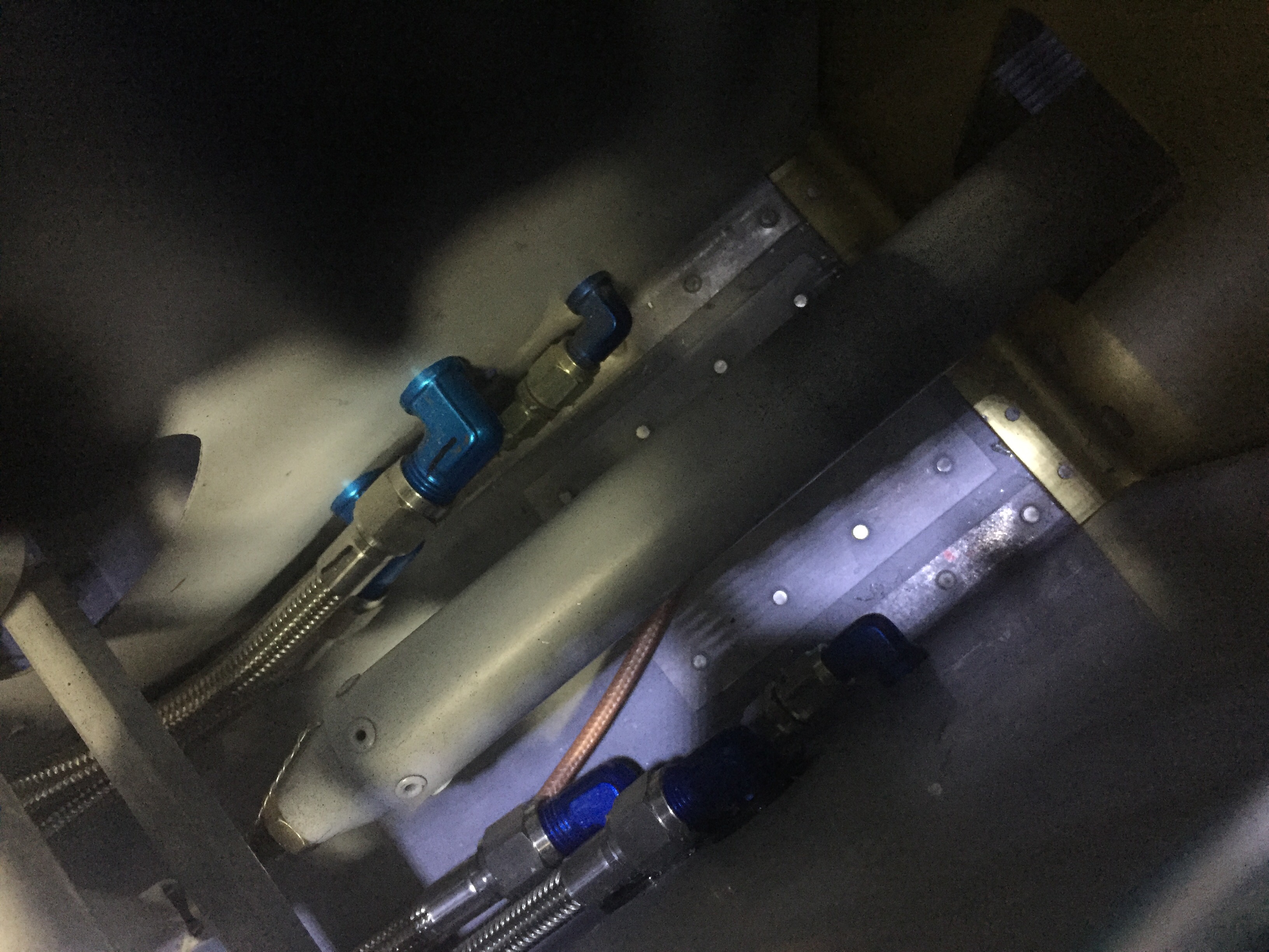
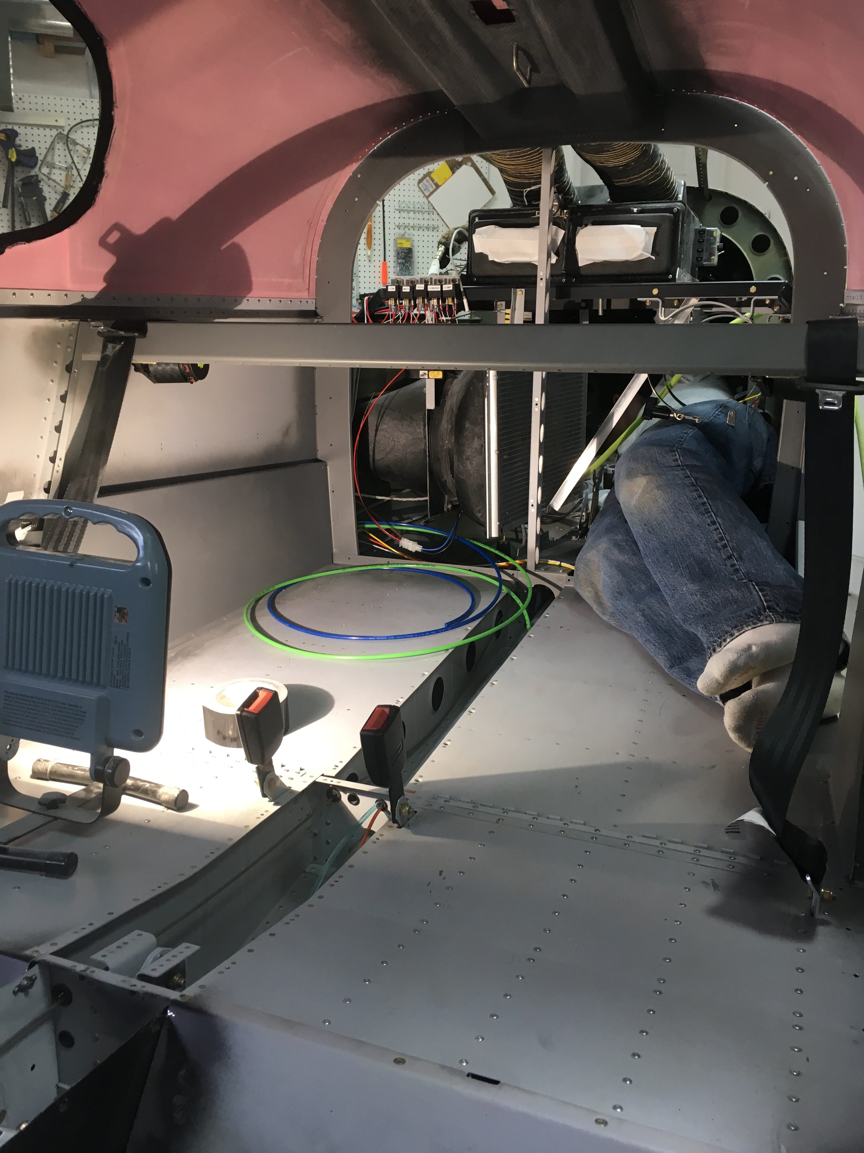
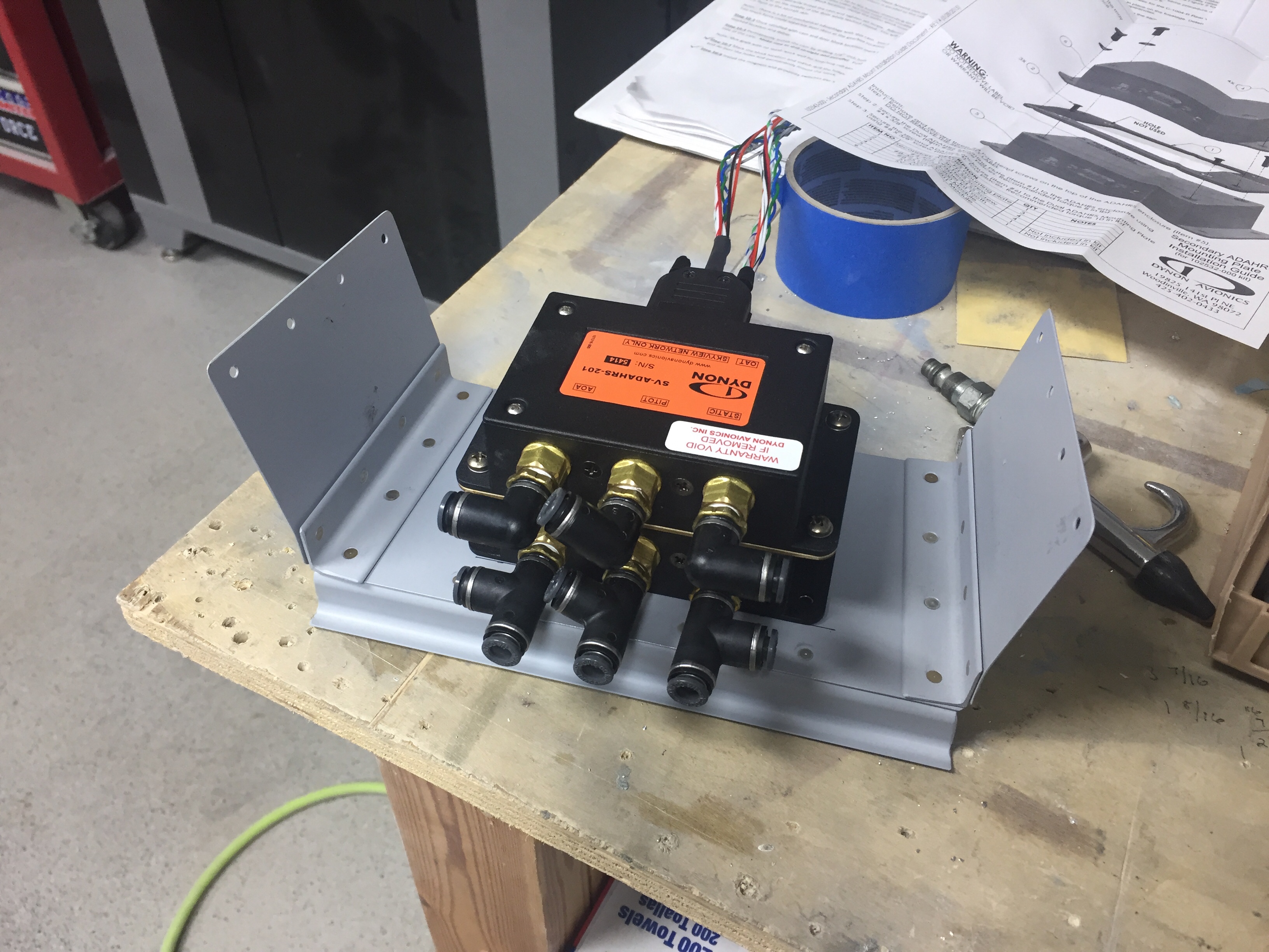
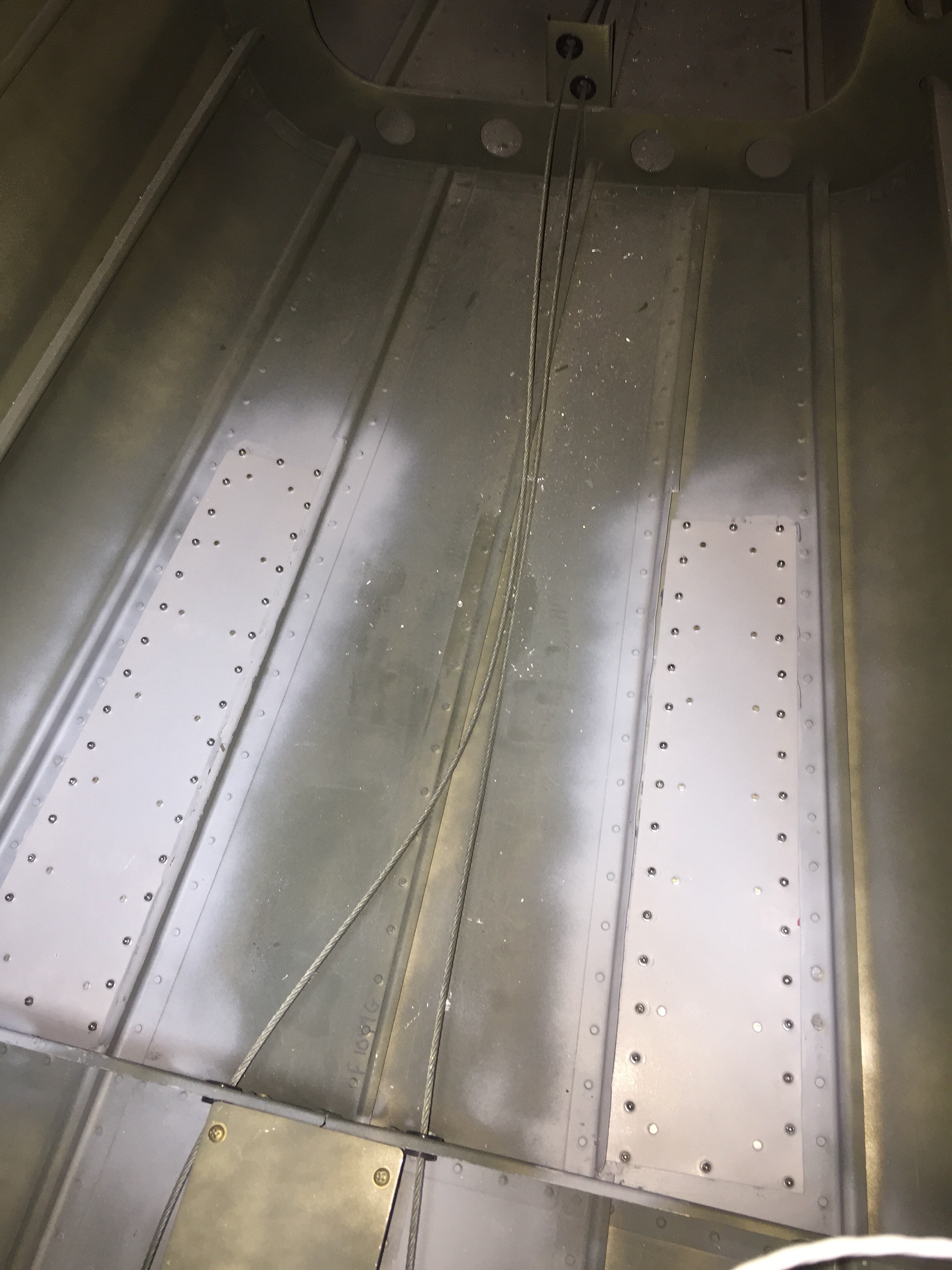
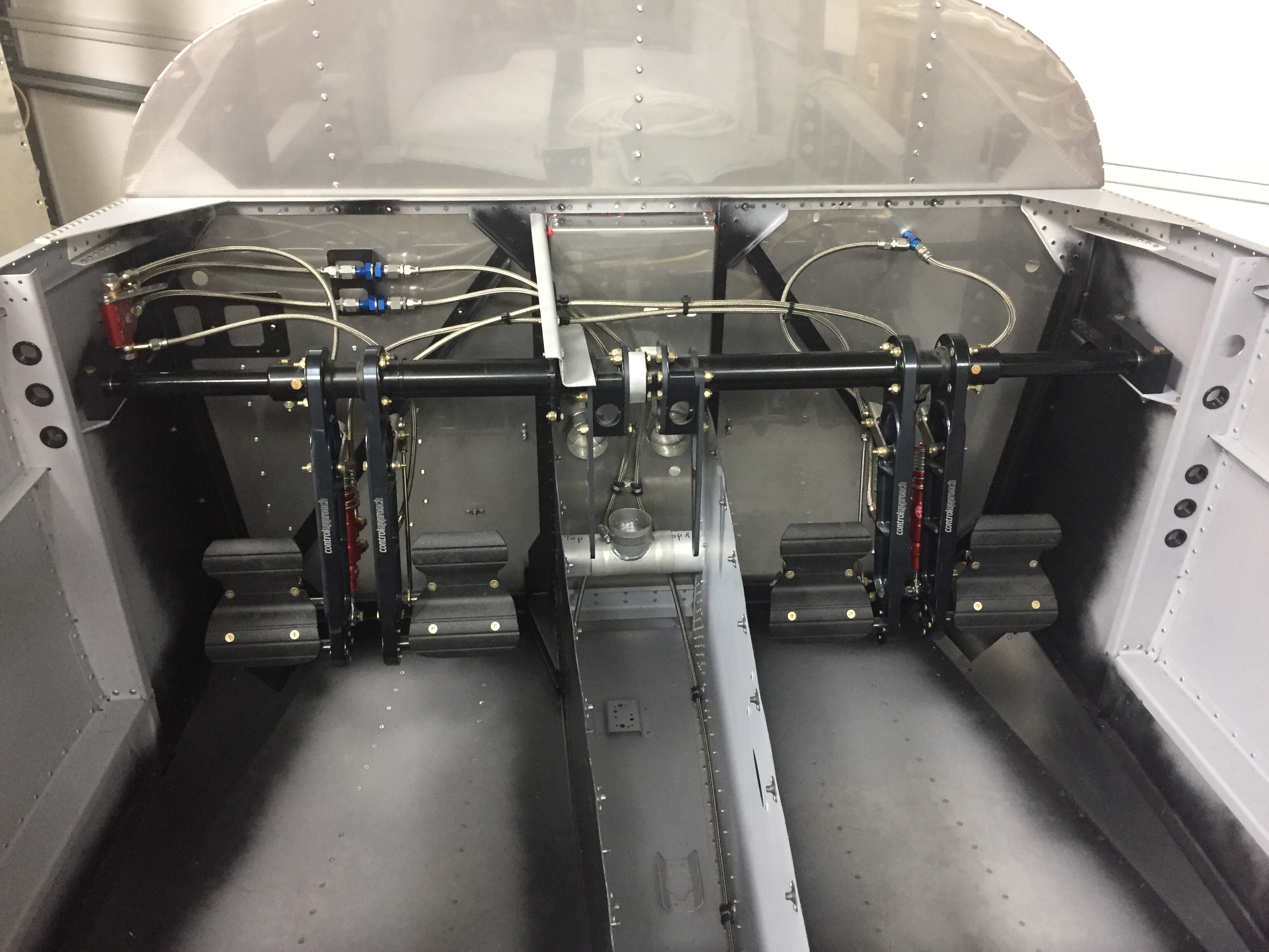
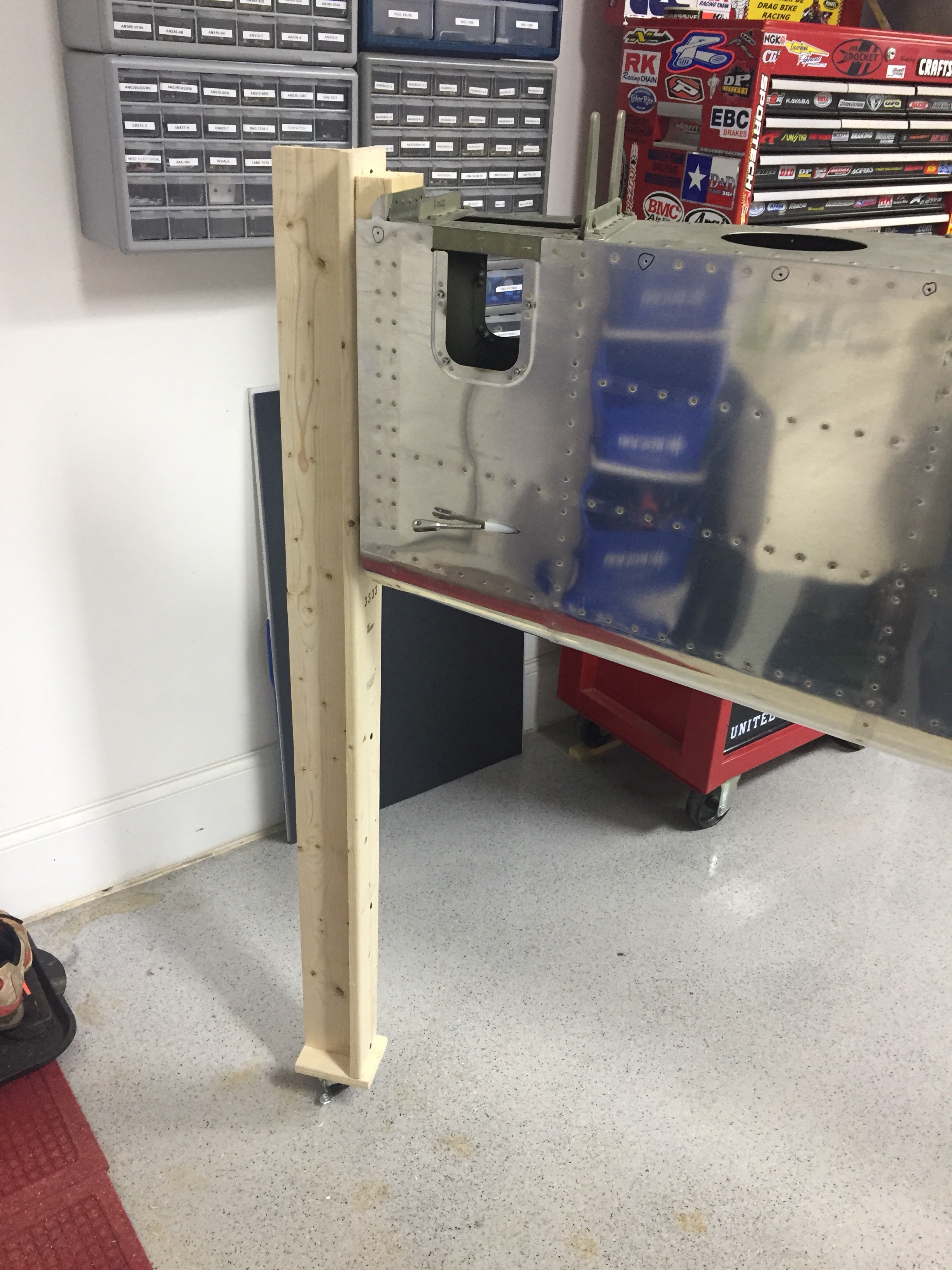
Inside the tail cone, I mounted the new static ports with pro-seal (no rivets this time) and hooked up static line that runs to where the ADAHRS will be mounted just behind the baggage bulkhead.  The new static ports look way better than the original ones and I’m happy I made the change.  The Safe Air 1 line kit makes it easy to run the tubing and create a leak free system.  I also ran the rudder cables through the bulkheads and snap bushings.  Ironically, the heads of the cables wouldn’t fit through the bushings without removing them and squeezing a bit.  So basically, the cables were a pain to run instead of a quick two minute job.  Lots of those in the build, I guess.   I got them hooked to the arms on the rudder pedals which are inside the tunnel with the Control Approach pedals.   With the A/C in there, it’s a tight fit for me!

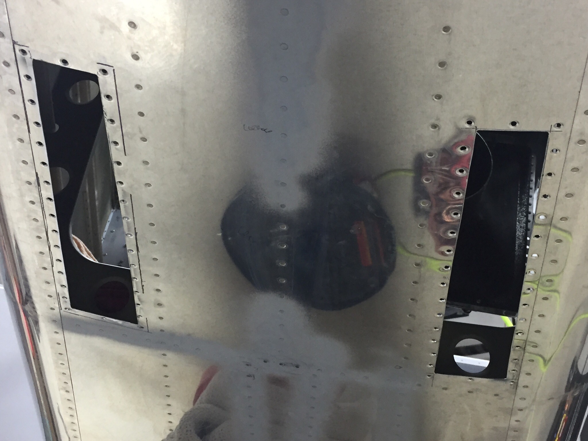
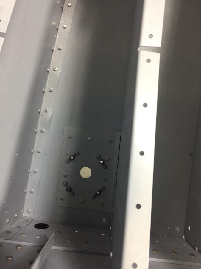
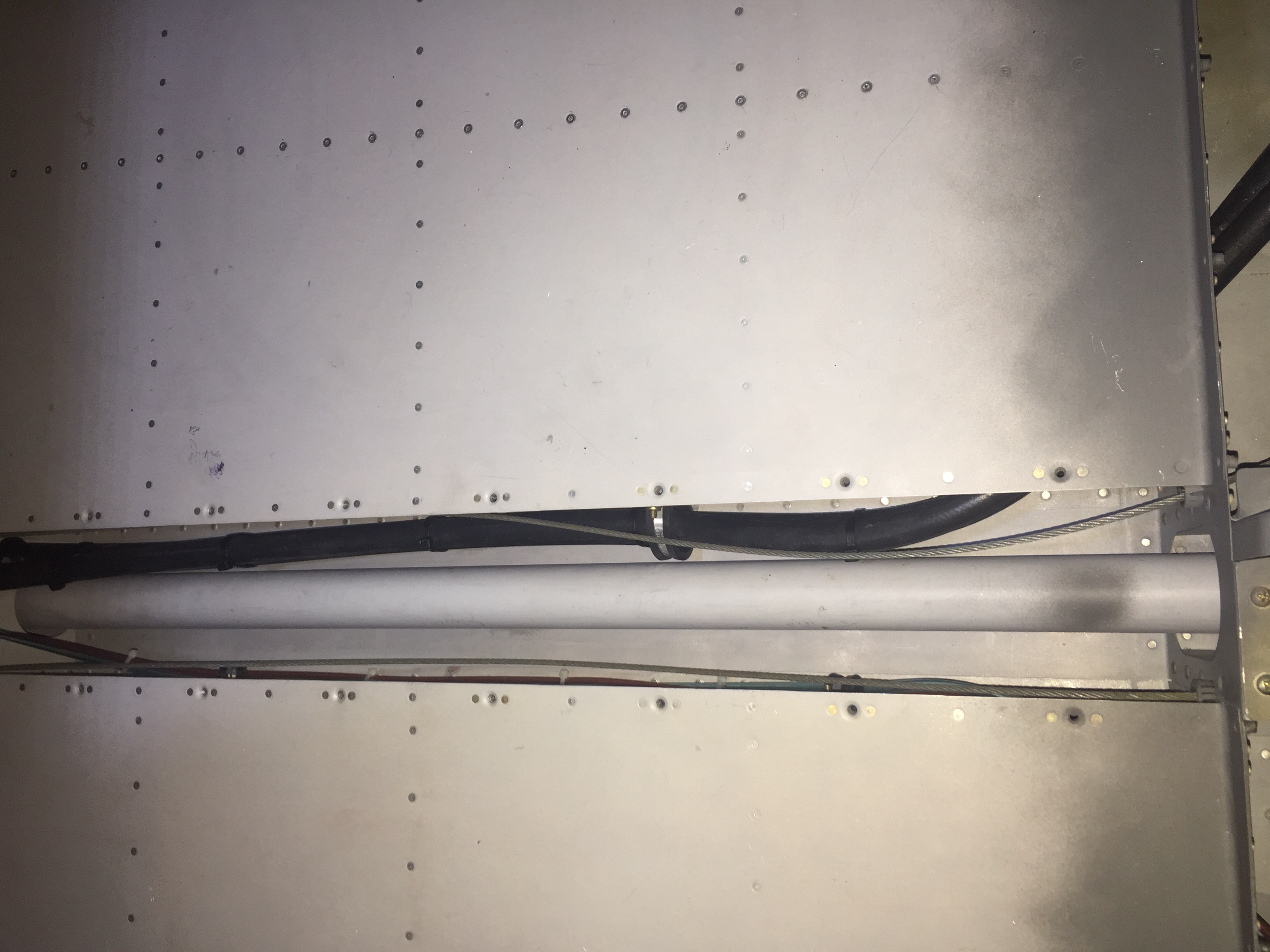
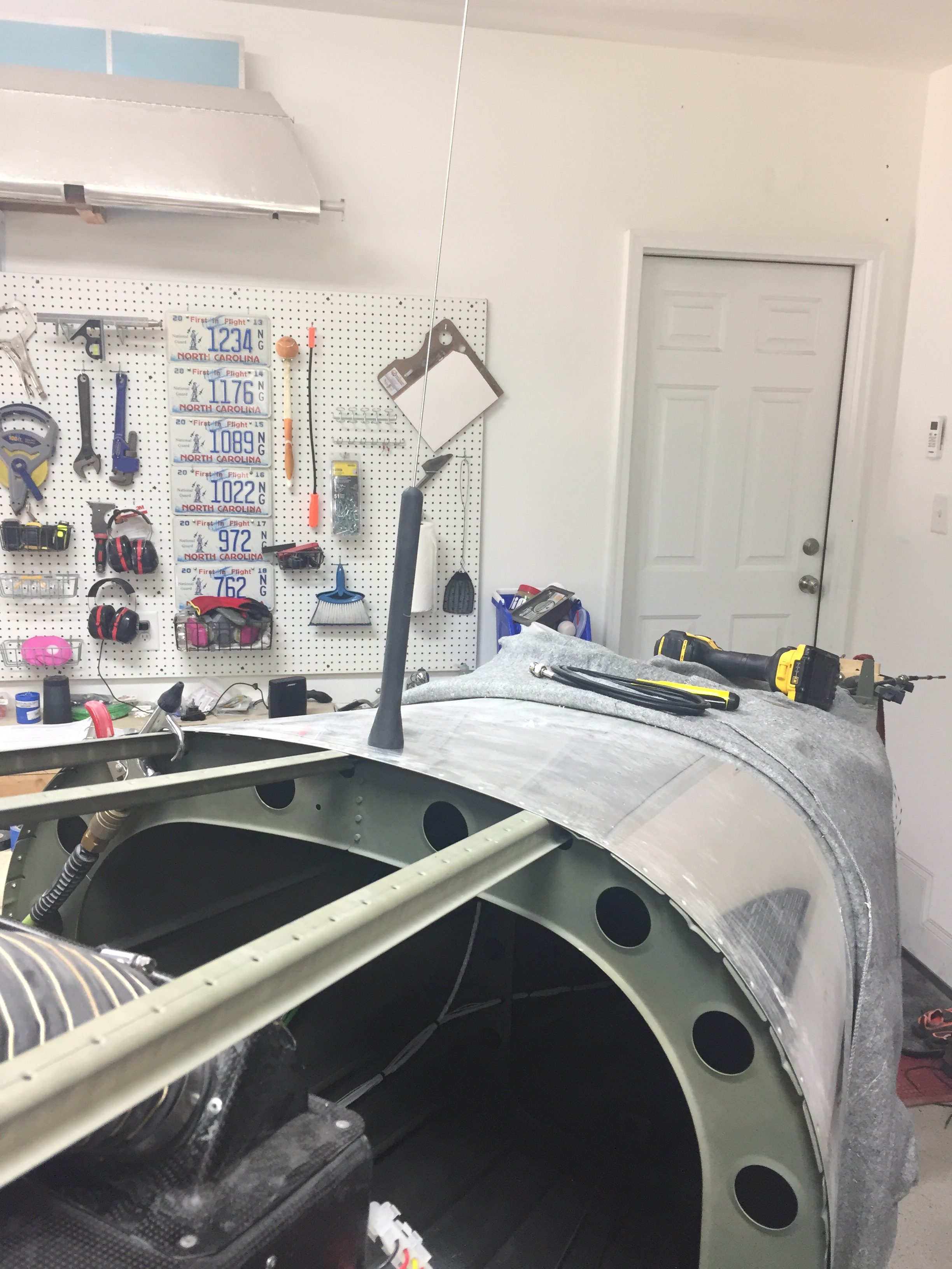
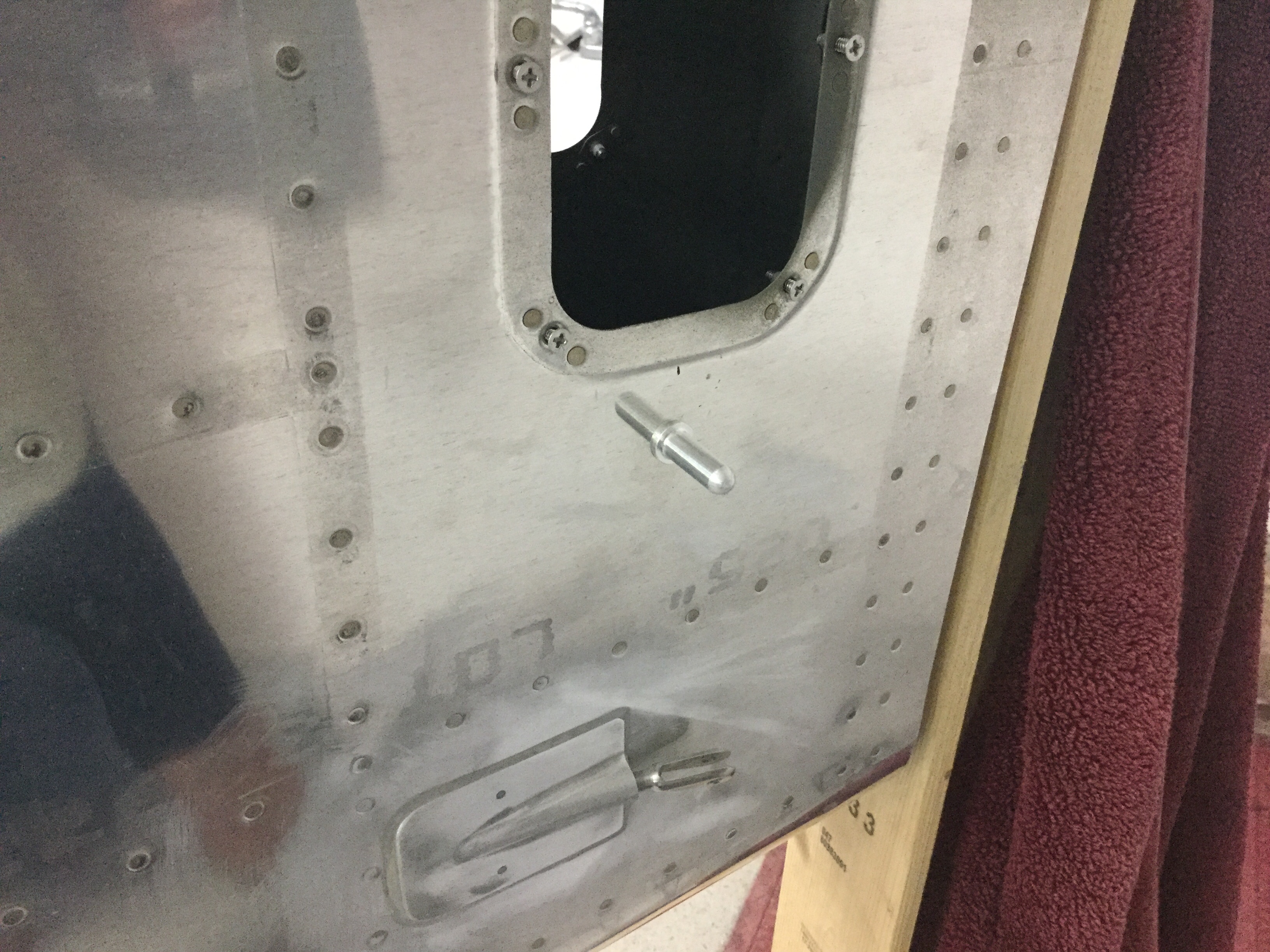
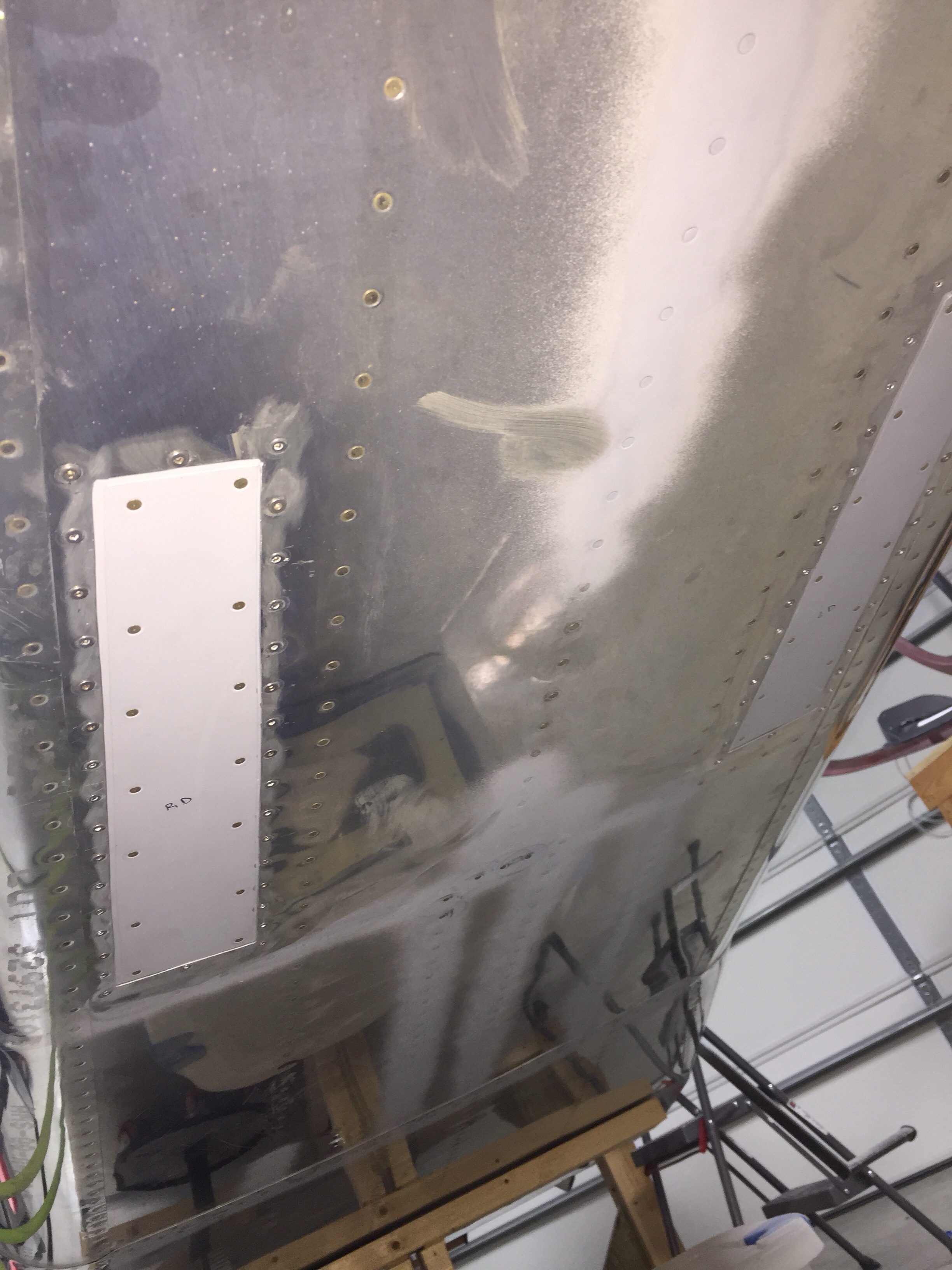
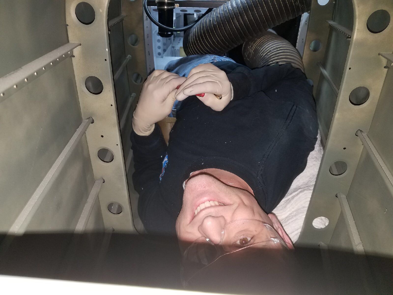
Lastly, I installed the doublers along the center of the fuselage for the transponder and ADS-B antennas to mount to.  These will be Delta Pop blades and mount with two studs, so I need access from the tunnel / fuselage.  Easy enough with a second set of hands to man the gun and me bucking.
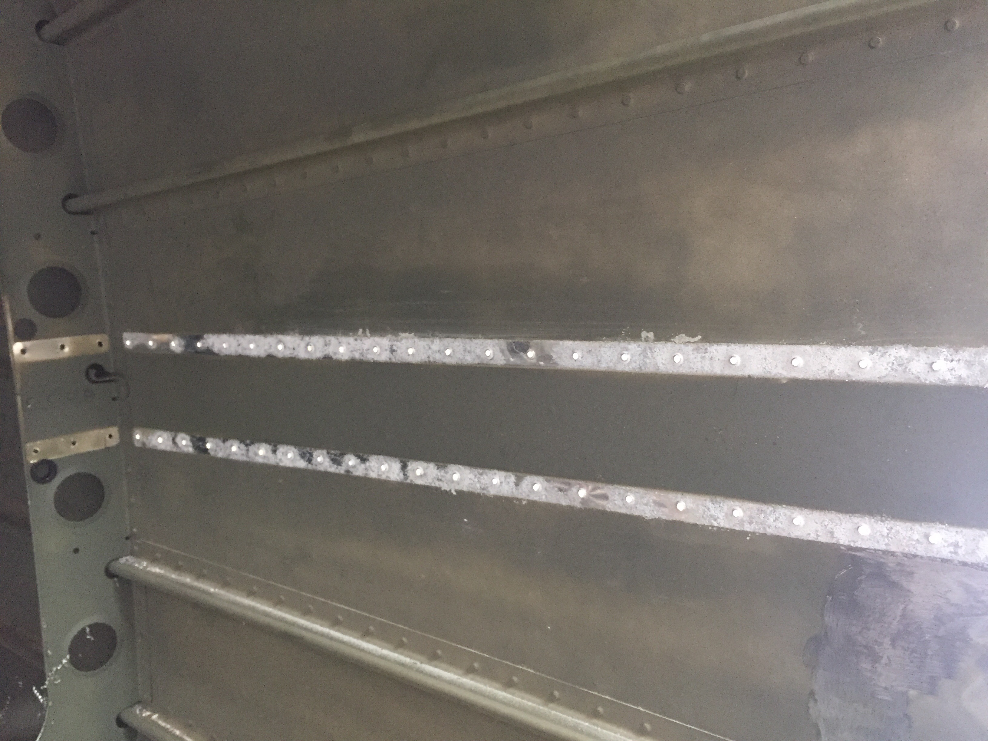
One F*&$#ng Bolt

Even though I don’t have the stabilizers mounted, I need to run the rudder cables so that I can start putting other components in the tunnel and move forward with systems layout.  The rudder cables get threaded through the tail cone skin and forward.  Unfortunately, the ends don’t fit through the snap bushings easily and will require me climbing into the tail cone to thread through the bulkheads.  More on that plan later.  I could, however, go ahead and clamp the plastic tubing to the fuselage using cushioned adel clamps where the cables exit the fuselage.  What should have taken about three minutes to put a clamp on and secure it with an AN3-5A bolt wound up taking over 30 minutes and resulted in a lot of frustration.  The clamp proved to be just springy enough that the threads wouldn’t engage and it’s already a tough spot to reach.  With my patience running out and my fingers sore from messing with the bolt, my gut instinct to scream profanities targeted directly at the airplane proved successful and I was finally able to get the little bastard in.  I will never, ever, ever take that bolt out.

Needing to lower my blood pressure and calm my headache not to mention my now very concerned shop dogs, I decided to move to another aircraft system, the pitot static system.  I ordered a kit from Safe Air 1 quite a while ago and have already installed the pitot tube mount with preliminary tubing in the wing.  When I built the tail cone, I used another brand static ports that after looking at for years had to go.  The Safe Air 1 ports are designed to be mounted from the inside and have a very clean look not to mention good reviews of functionality.  Since I was going to have to crawl in the tail cone anyway, I decided to remove the current ports to prepare for the Safe Air 1 version.  I had to drill out the four rivets, clean up the holes, dimple them, and make a patch.  The patch is required since the original ports had a half inch hole required.  I had to get pretty creative on how I dimpled the holes since I can’t get the pliers or squeezer on it.  I wound up using the blind rivet nail trick with the dies designed for a finish nail with great results.  Once the patches were made, I used blind rivets that sit nicely in the skin for ease of use and negating one more task of bucking rivets while crawling in the cone.  Since I’ll use flox filler to smooth out the hole anyway, the blind rivets will disappear.  I’m really happy with the result and quickly relocated the new port hole just below the original location.  I don’t anticipate any issues with the new location.

I also installed the avionics shelf that I had fabed previously with the proper spacers and screws.  I plan to use nutplates for permanent mounting of components once all of the boxes are laid out.  I’m preparing everything I can think of to do while crawling in the tail cone to include mounting the new static ports, mount the static line and clamps, route the rudder cables, install snap bushings for tail wiring, and run string to pull future wires.

Are you a bit warm? Turn on the A/C

With the tail cone attached, I wanted to get the Flightline A/C system installed before too much else gets put in which would make access difficult. The majority of the system is located behind the baggage bulkhead, so it’s easy to get to right now. The first step is to mount the condenser tray onto the longerons which is simple enough. I spent some time cleaning the air handler up and getting all the old dust off of it. I also cleaned up the insulation a bit and used foil HVAC tape to seal the remaining uninsulated areas. I fixed a couple of nasty looking nutplate rivets on the tray as well before putting it in the airframe.

The next task was to mount the intake and exhaust vents for the condenser. While at Oshkosh, I spoke with John at Flightline (owned by Kelly Aerospace now) about an alternate side mounted intake. There have been some builders concerned about CO infiltrating the cabin with the original belly mounted vents which are in the exhaust stream. I agreed to design a new side mount intake similar to Cirrus retrofit kits. While I am in the process of laying up said vent, I ultimately decided that I was comfortable with the stock setup and ended up going that route.

I created a paper template of the vents after cleaning the old silicone caulking from them and cleaning up the rivet holes (this was a used kit pulled from a flying RV-10). I used the template to mark the holes and cut lines on the bottom of the tail cone. I measured fifteen times and cut once with success!

I used black RTV to create a good seal around the vents which will prevent air from leaking into the cabin area. Once riveted in, I was really happy with the results and finished up by connecting the 6″ duct work to the plenum and securing the clamps. I also added a new drain line from the evaporator which runs down into the exhaust vent and secured it using more RTV.

I’m really excited to have this done and happy with how it turned out. I chose this kit vs the Airflow system because of it’s low profile install and electronic controller which is really slick. Users have reported good performance and this will make our adventures even more pleasant by keeping the cabin comfortable in the southern summers.

We have some catching up to do

Time has gotten away from this blog, so I have quite a bit of catching up to do. I also must admit that there were more than a few months that snuck by with no progress made on the project due to work, life, and other priorities. I’m happy to report that I’m back on the project nightly and am really making some exciting progress.

I left off with the tail cone repair and prepping to join the two sub structures. It was very anti-climactic to be honest! One rib worth of rivets required a bit of help from a friend to hit some rivets and boom, it was on for good. It really is starting to look like an airplane, or at least a canoe at this point. I’m very happy about the cradle on wheels, as the shop is getting a bit cramped on space, although I’m confident it will still be a nice workspace for the remainder of the project.

I pressed on with the steps, as you can see above and used the TCW step bushings to prevent the mounting bolts from crushing the tube and creating issues down the road. I attached the antenna doubters and am happy with the results. They are actually under the rear seat pans, not the baggage floor as previously mentioned.

Next up is the baggage floor, rear seat pans, and rear bulkhead. Lots of drilling, deburring, and priming but the work went fairly quickly. One thing that has always impressed me is the size of the cabin in the RV-10 and now that mine is coming together, I had to see how roomy it actually is. First time sitting in the plane! And no, I didn’t make any airplane noises quite yet since I was sitting in the back seat. Plenty of leg room.

Lot’s more to catch up on in the next post.

Taking a new stand

After drilling out all the rivets and removing the two ribs with feared corrosion, my suspicions were confirmed with a somewhat scary sight.


As you can see, there was quite a bit of corrosion between the two surfaces.  I’m very happy I took the time to correct this and avoid potential problems down the road.  I spent more time inspecting other areas of the tail cone and could find no other signs of corrosion, so I’m confident this is the extent of the damage.  It took a few 3M pads to get all of this cleaned up, but after about an hour it was down to shiny smooth metal again.  I was concerned about how much I had to grind away on the bulkhead, but a call to Vans alleviated my fears as they said I should be good to go.  I removed the original primer (which was not applied very well, I admit) and did a thourough wipe down with MEK before properly priming with my SEM.


I did notice a small stress crack in the bulkhead lightning hole flange that I stop drilled upon Vans’ advice.  I was able to move forward after this brief fix delay and was back on track.  However, the next step was to mate the tail cone to the fuselage assembly.  That requires getting rid of the sawhorses and coming up with a long term stand for the fuselage structure.

I checked out a few other build logs and decided to copy Justin Twilbeck and went with a four caster design with pillars for each side of the spar pass through and one each for the firewall and bulkhead near the steps.  Using 2x4s and some OSB, I estimated the deminsions putting the structure at a nice working height, keeping in mind the cabin top and the height of my garage door.  I won’t be able to mount the gear free hanging on this stand, but it will allow easy access and a comfortable working height for the next year or so.  I put a bit of felt on the two bulkhead cross pieces and am pretty pleased with how securely it holds the fuselage.  It also rolls quite easily which is good because the shop is filling up quickly!


Next up is actually mating the tail cone to this subassembly.