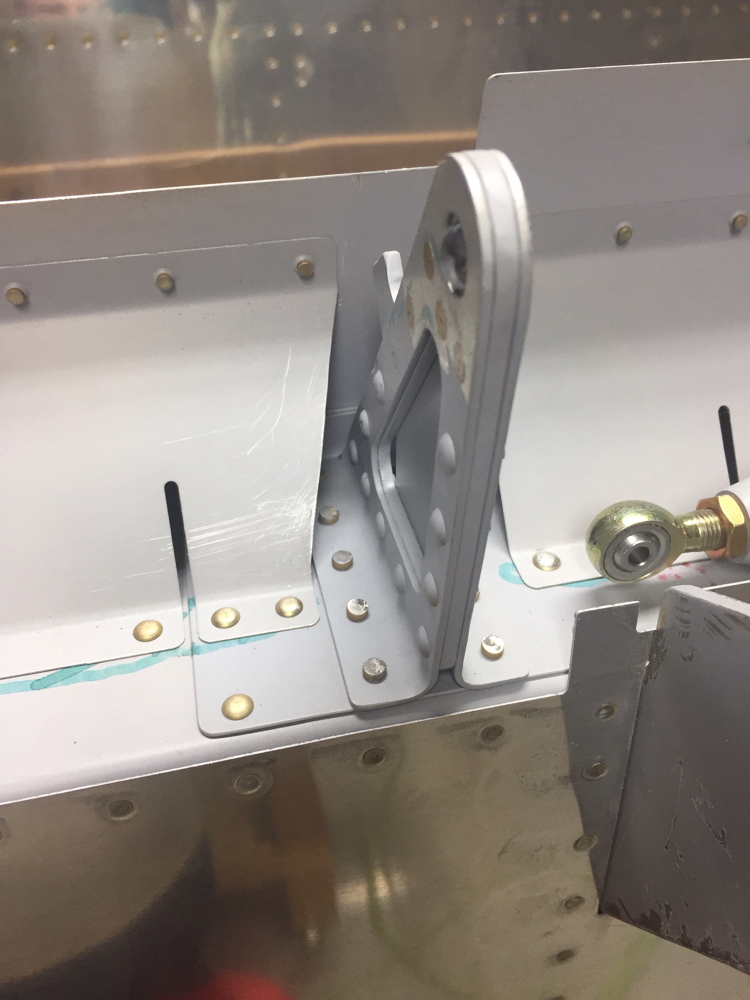
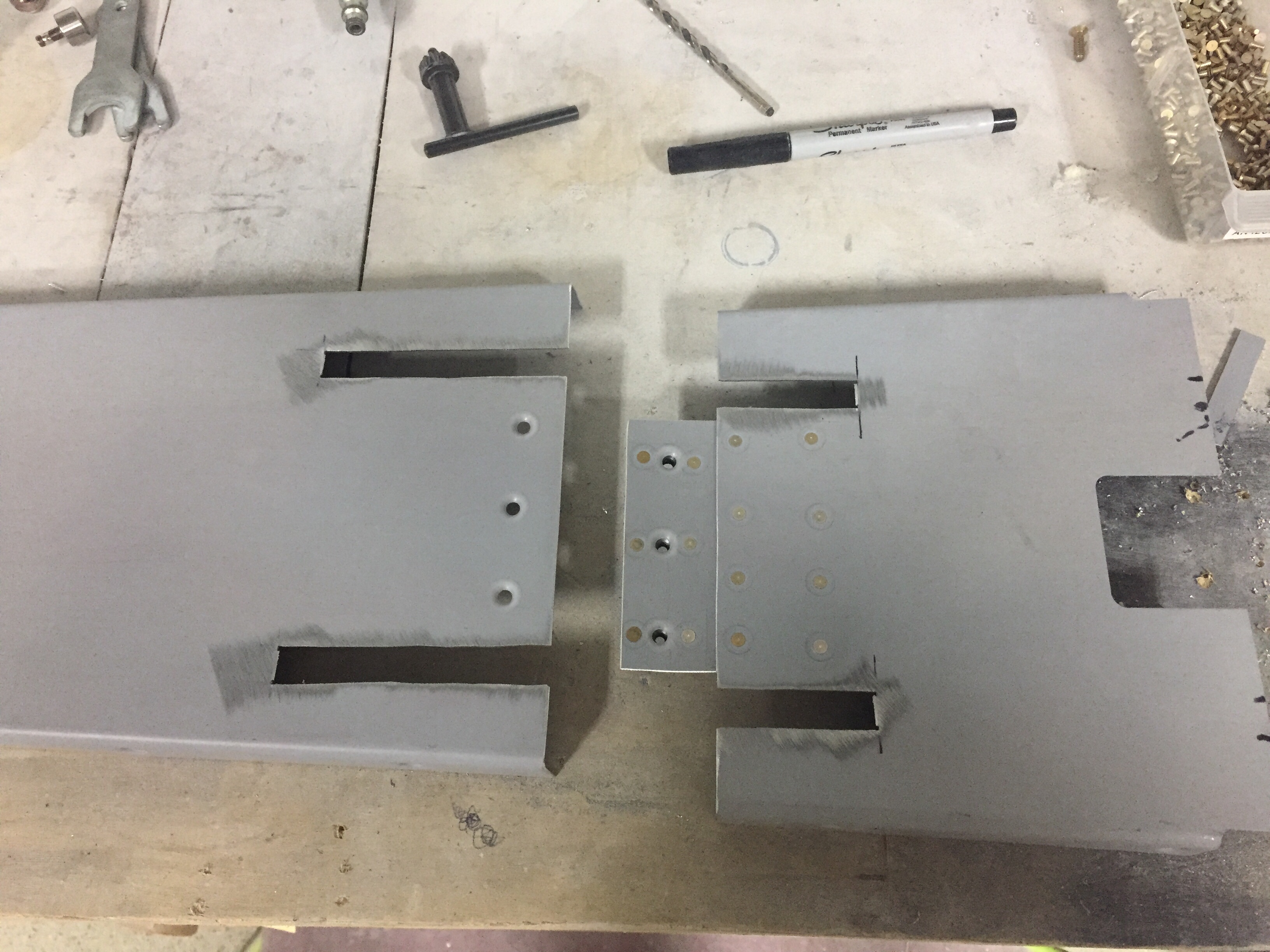
One task that I want to document for others I forgot to mention is modifying the tunnel cover around the Control Approach rudder pedals. The cable attach arms are relocated inside the tunnel so slots need to be cut for them to move freely in the cover. I measured their arc and marked the tunnel cover where I wanted to split it into two pieces. Before cutting, I marked and drilled a center plate to hold nut plates which will allow me to screw the two pieces back together. It was a pretty simple modification as was cutting the slots for the arms in each piece. Again, I’m trying to consider maintenance and access down the road as much as I can.
I also took the time to modify the seat rails since I got the Aerosport seat levers. Others have described this mod and it makes removal of the seats a snap. Step one is to remove the delrin guides from the seat bottoms and trim the first 1 ½” off followed by reinstalling them. This allows the seat to be slide rearward on the rails and then tilted around the flap tube cover with the necessary clearance. I then removed the aft rail stop and drilled through the rail into the plate below. Installing nut plates below the plates lets you put bolts in place of the screw and nut on the stop. Now, I can get to the bolts from the top down eliminating the need to reach under the seat plate to get the lock off, allowing the seat to slide freely rearward. It all makes sense when you look at it.
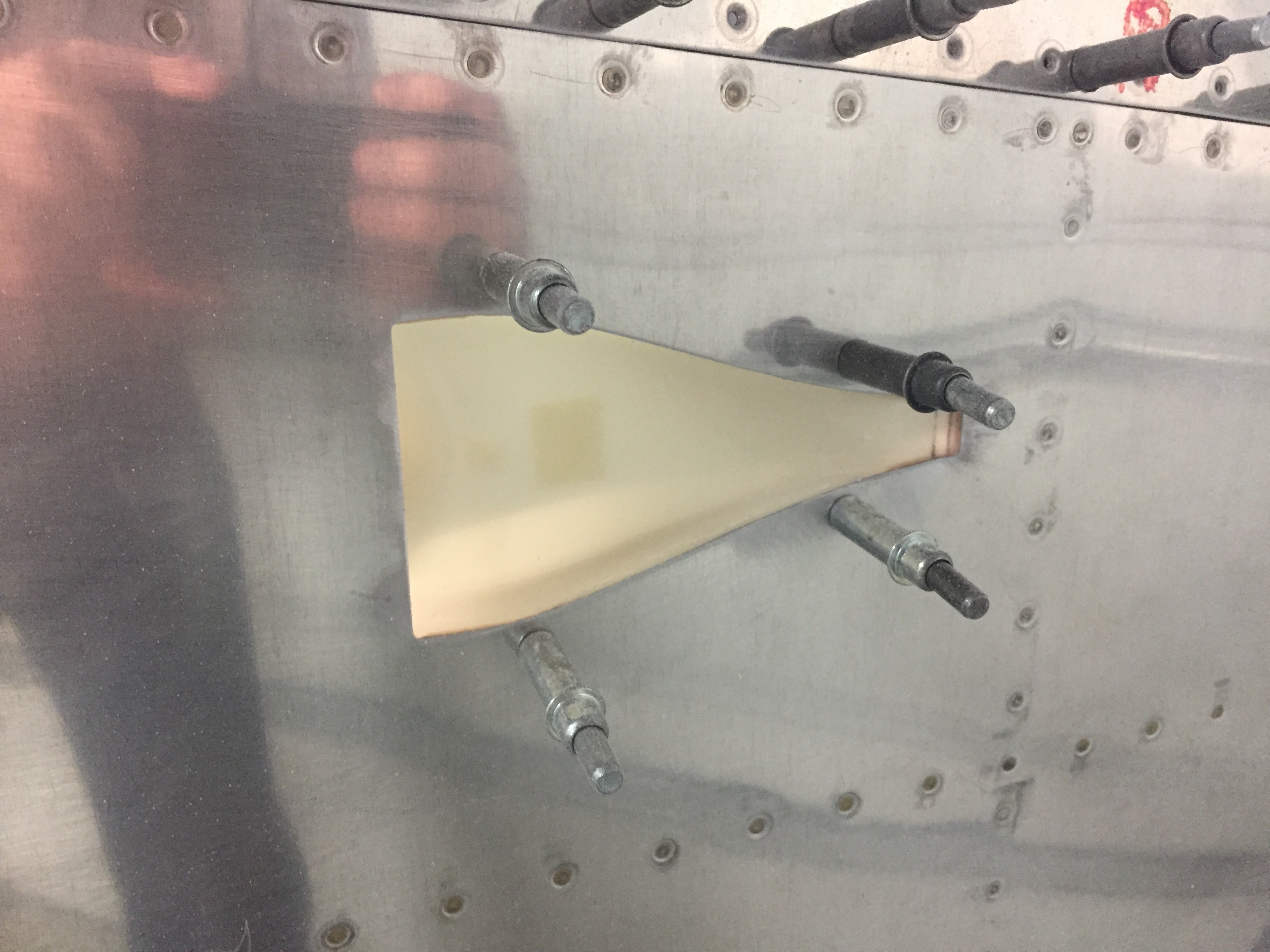
I’m trying to knock out some little side tasks along the way now in the spare time. I used some excess epoxy from a door filling session to install the front vent NACA scoops. I drilled a few holes and used clecos to hold them in place while the flox cured overnight. I don’t have proseal and didn’t want to use any silicone on the area since it will be painted. With minimal flexing and a good scuffing on both surfaces, I am confident the epoxy will hold these just fine long term. The scat tube will have a short run from there to the Aerosport vents that I installed in the instrument panel.
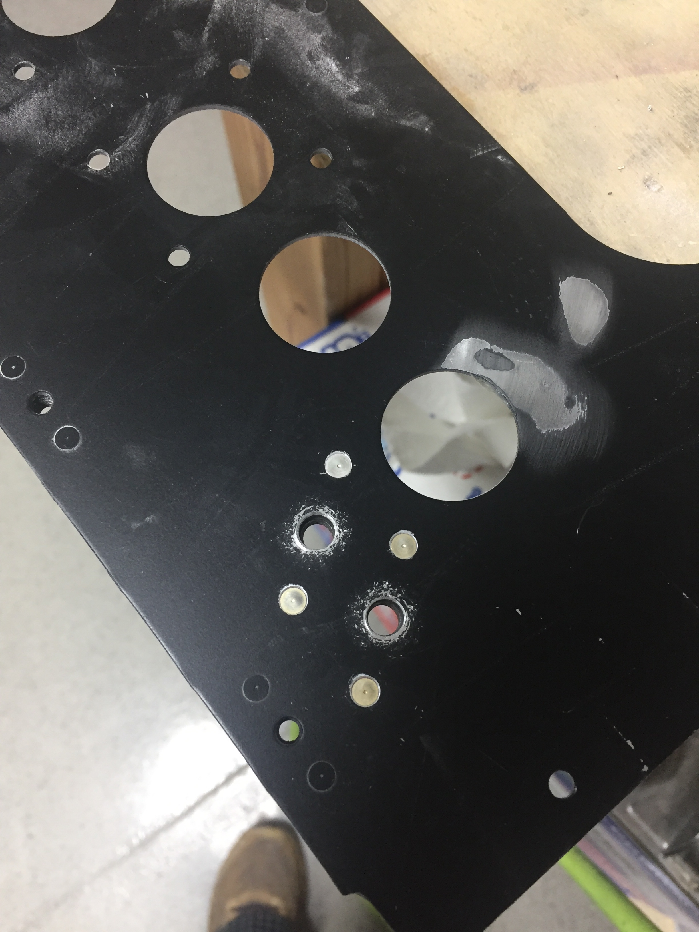
I also performed a quasi service bulletin from Sean at Plane Around. When I received the lights from him for the overhead and doors, several had bad boards which he promptly replaced. I got a call from him with an interesting finding. He used a brass wire over a piece of foam to hold the LED boards inside the aluminum and plastic housing. He found that in a few instances, the wire was touching the board and shorting out LEDs. Awesome service! He called and suggested using a different method such as silicone which is an easy solution. I removed all of the installed lights and completed the rework after ensuring all LEDs checked good. I took the opportunity to install the micro molex connectors on the remaining few assemblies as well.
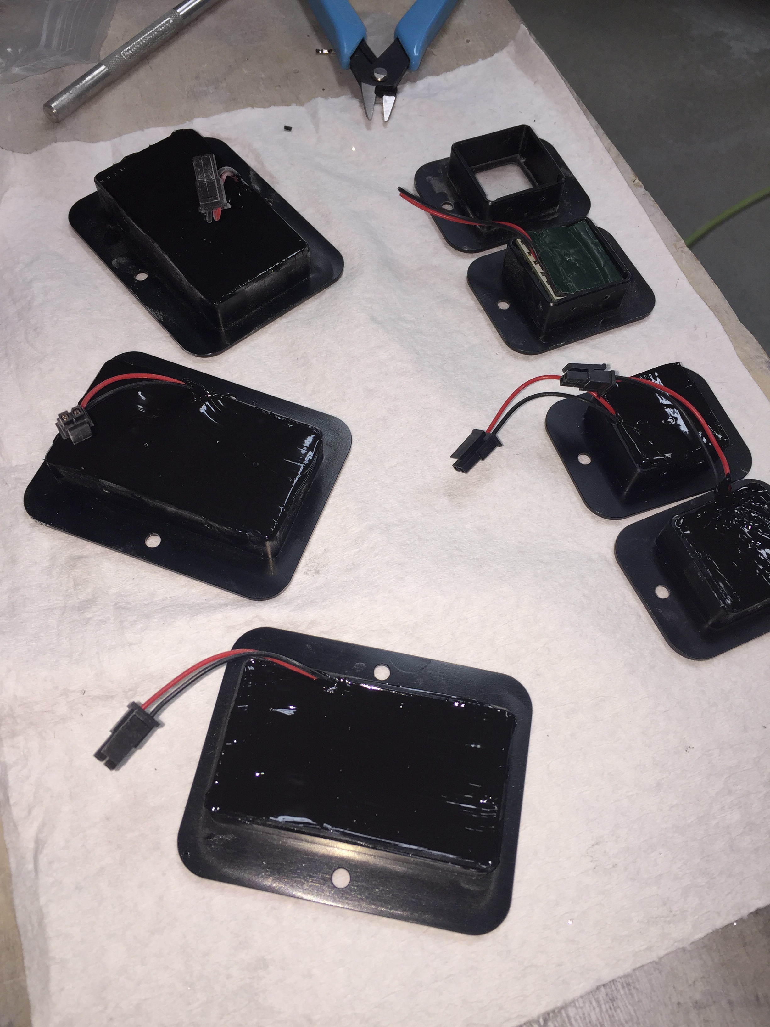
Service bulletin complied with in accordance with published guidance, OPS check good!
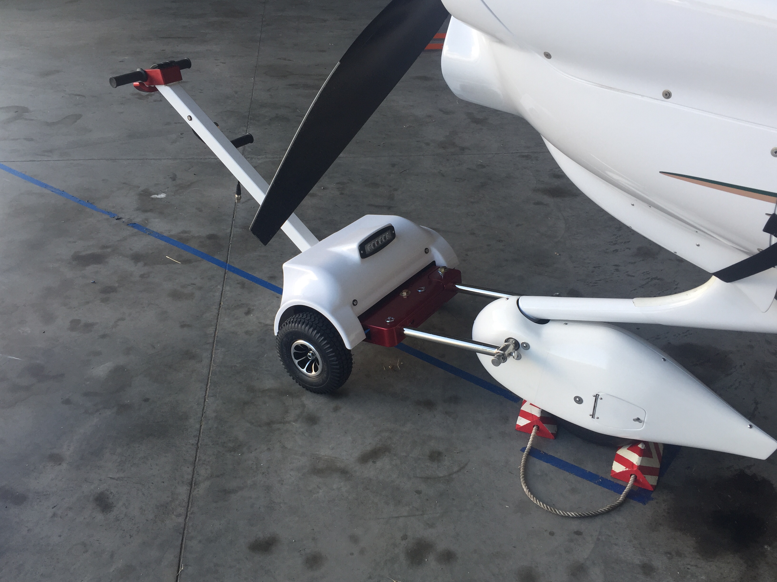
And finally, another cleanup item to mention was the addition to the hangar family. While she hasn’t been officially named, our new Best Tugs Alpha 2 arrived! I ordered this at OSH last year to use on the DA-40 we fly now and for long term with the RV. It cost a pretty chunk of change (plastic, let’s be honest) but man is it nice. It will save my twice-operated on back for years to come and is really handy to maneuver the airplane around. It took a bit of practice one afternoon but now it’s just like pushing a shopping cart! I requested the smooth cover with the intention of having it painted by Jonathan to match the RV but didn’t realize the red anodizing was going to arrive. Oh well, not the end of the world.