Splash of color and an Oops

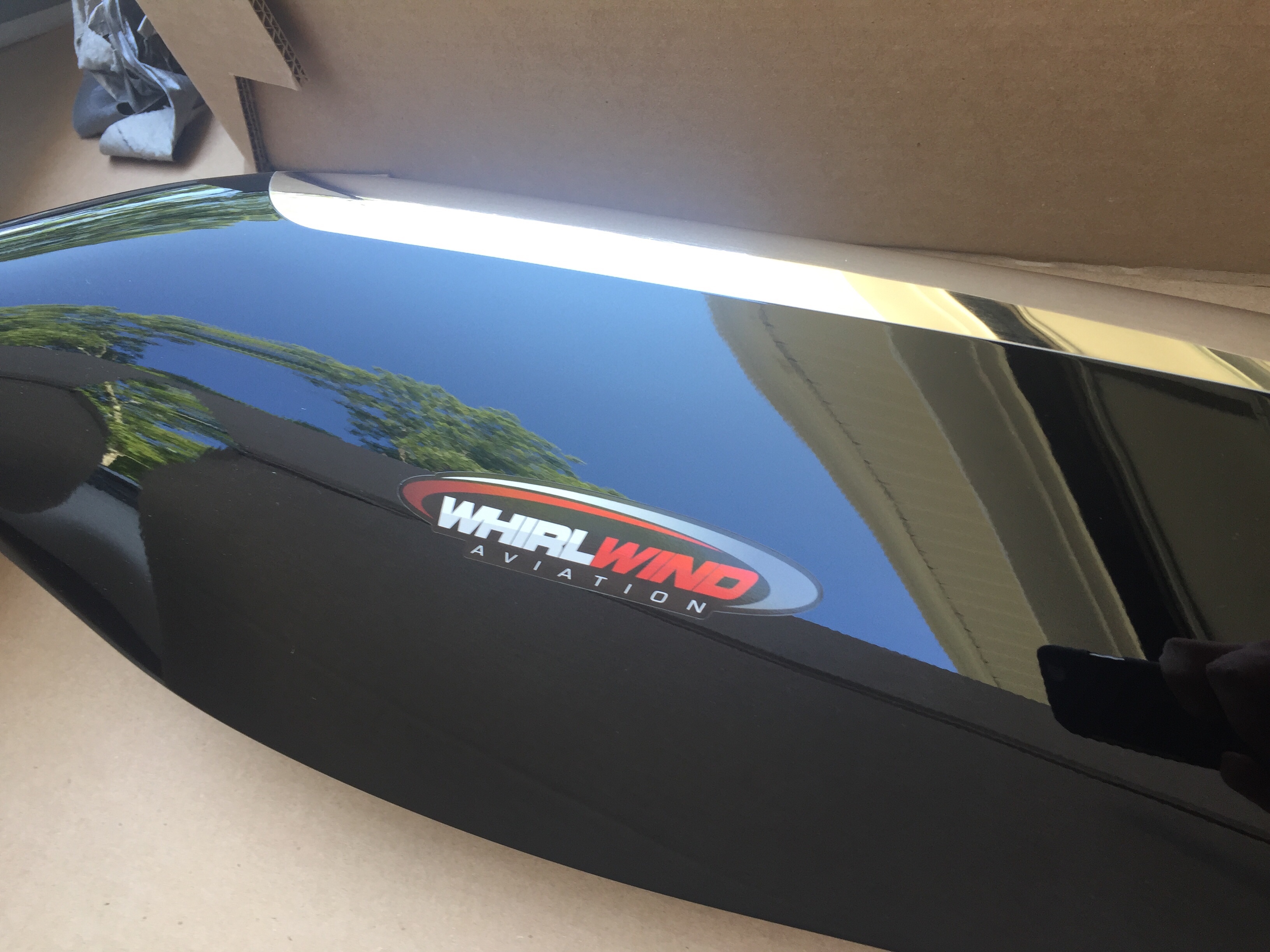
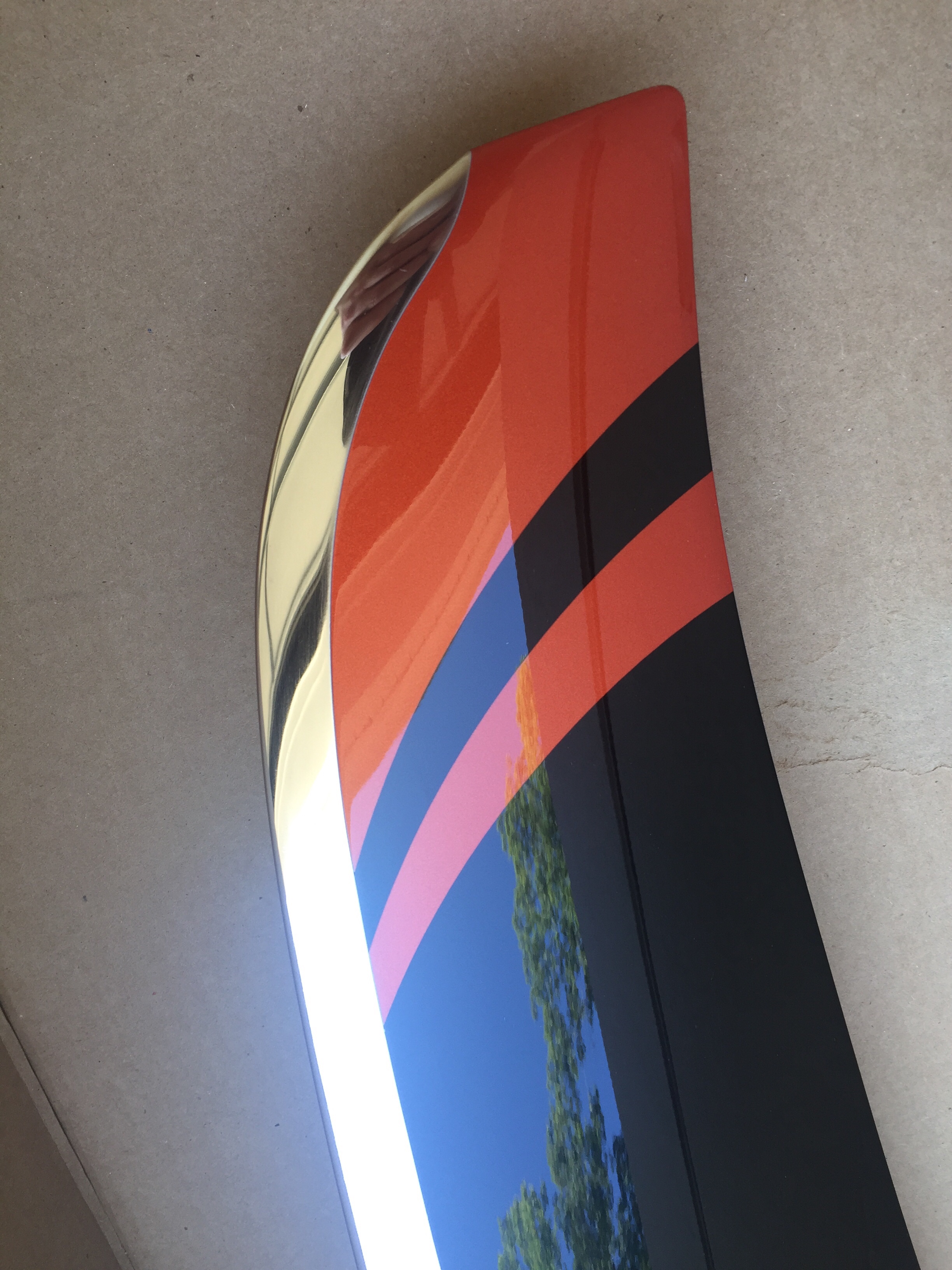
After returning from our trip up north, only a few days passed until we received a big package with a piece of art inside.  Our (second) propeller has arrived!  Whirl Wind delivered about a week late, but with prior coordination and communication with me so I was super excited to see what it looked like.  As chronicled earlier in the build, I purchased a propeller but decided to sell it instead of it hanging on the wall for three years before I was ready for it.  Joe Keys, you can’t have this one.  I knew I wanted another WW and the HRT blade is now a refined blade profile and is simply stunning.  Our orange was color matched and looks great with the black and nickel leading edge.  For now, the prop will go to a friend’s hangar to hang out with the wings until we move to the airport.

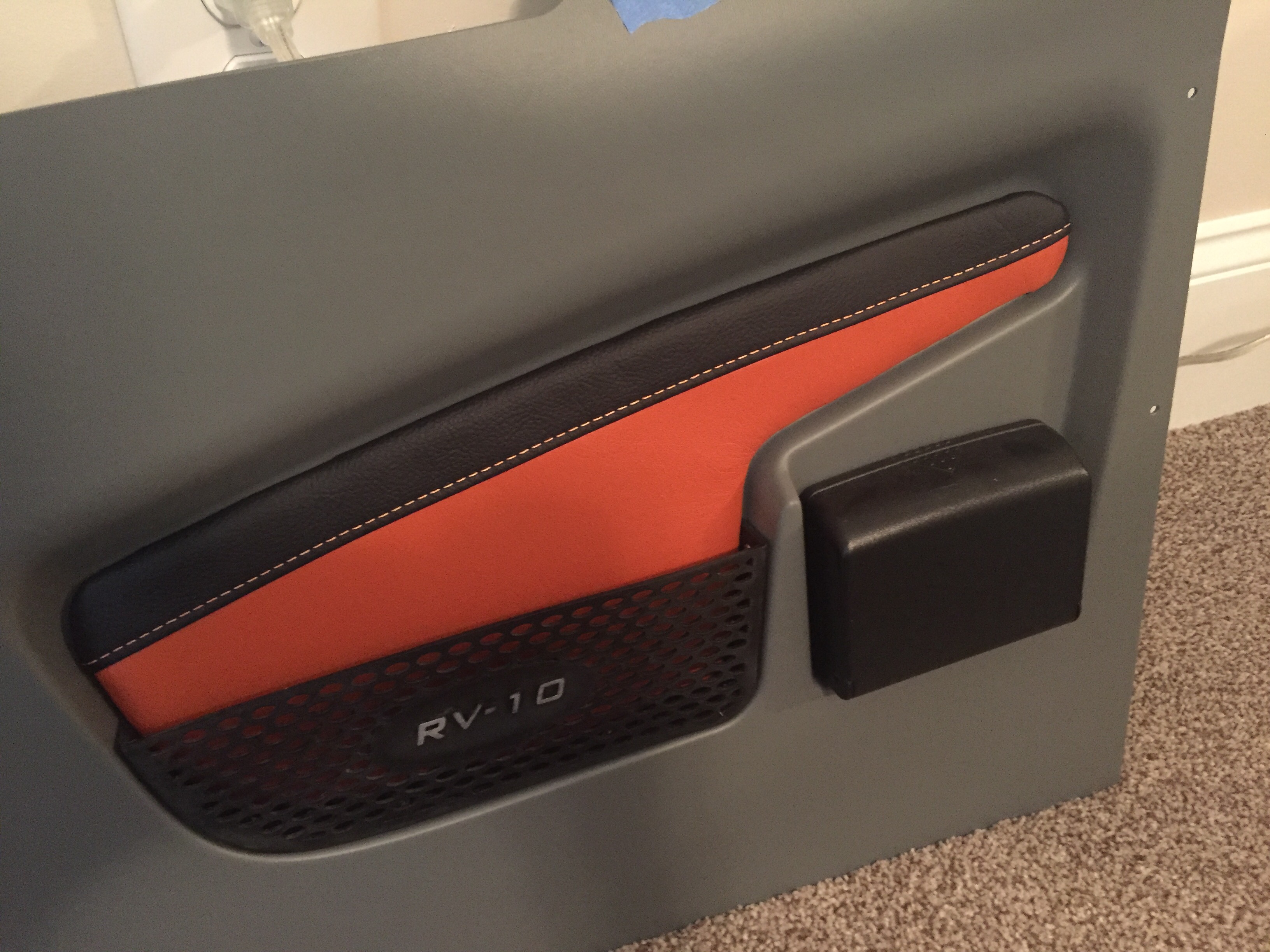
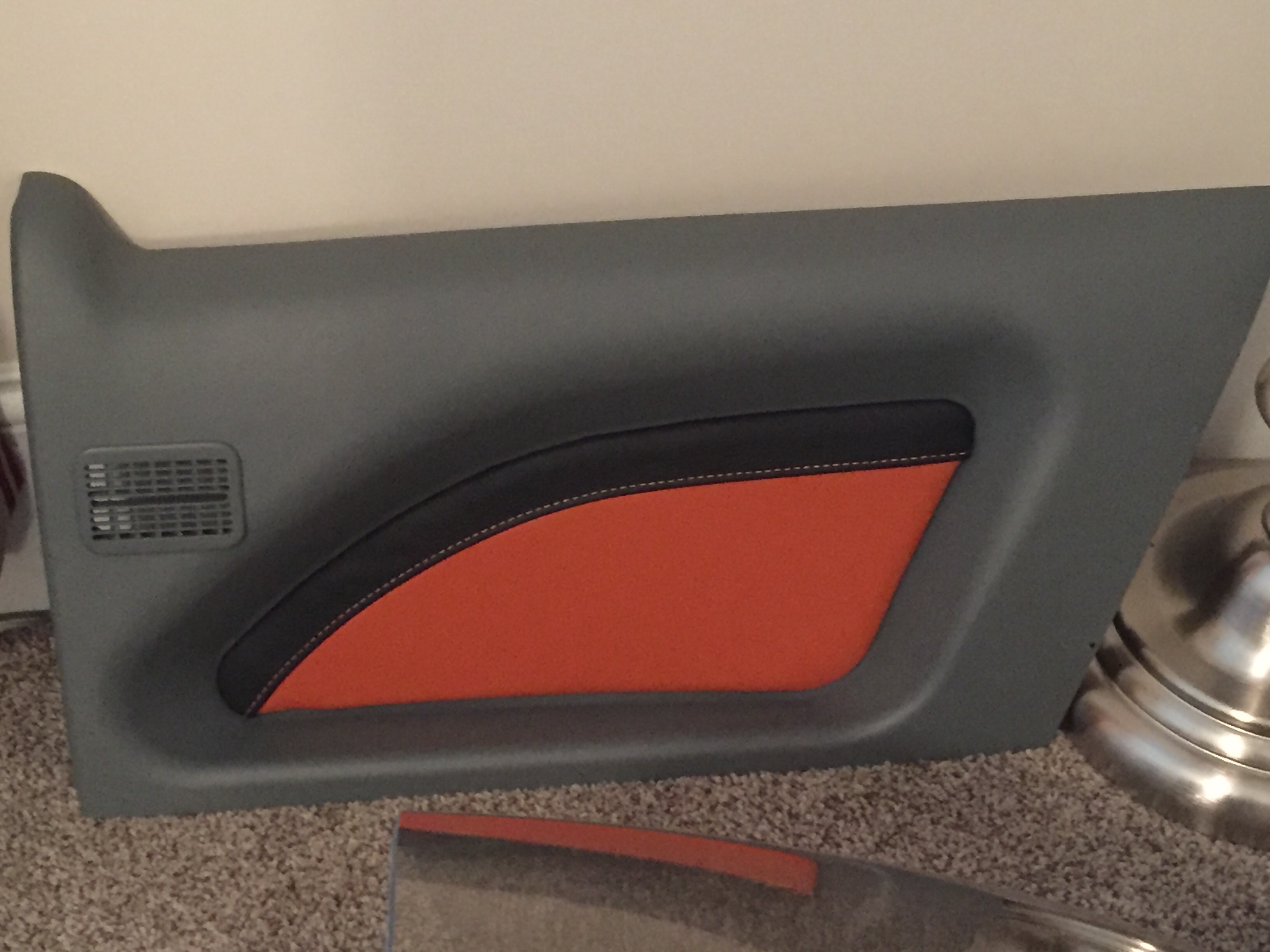
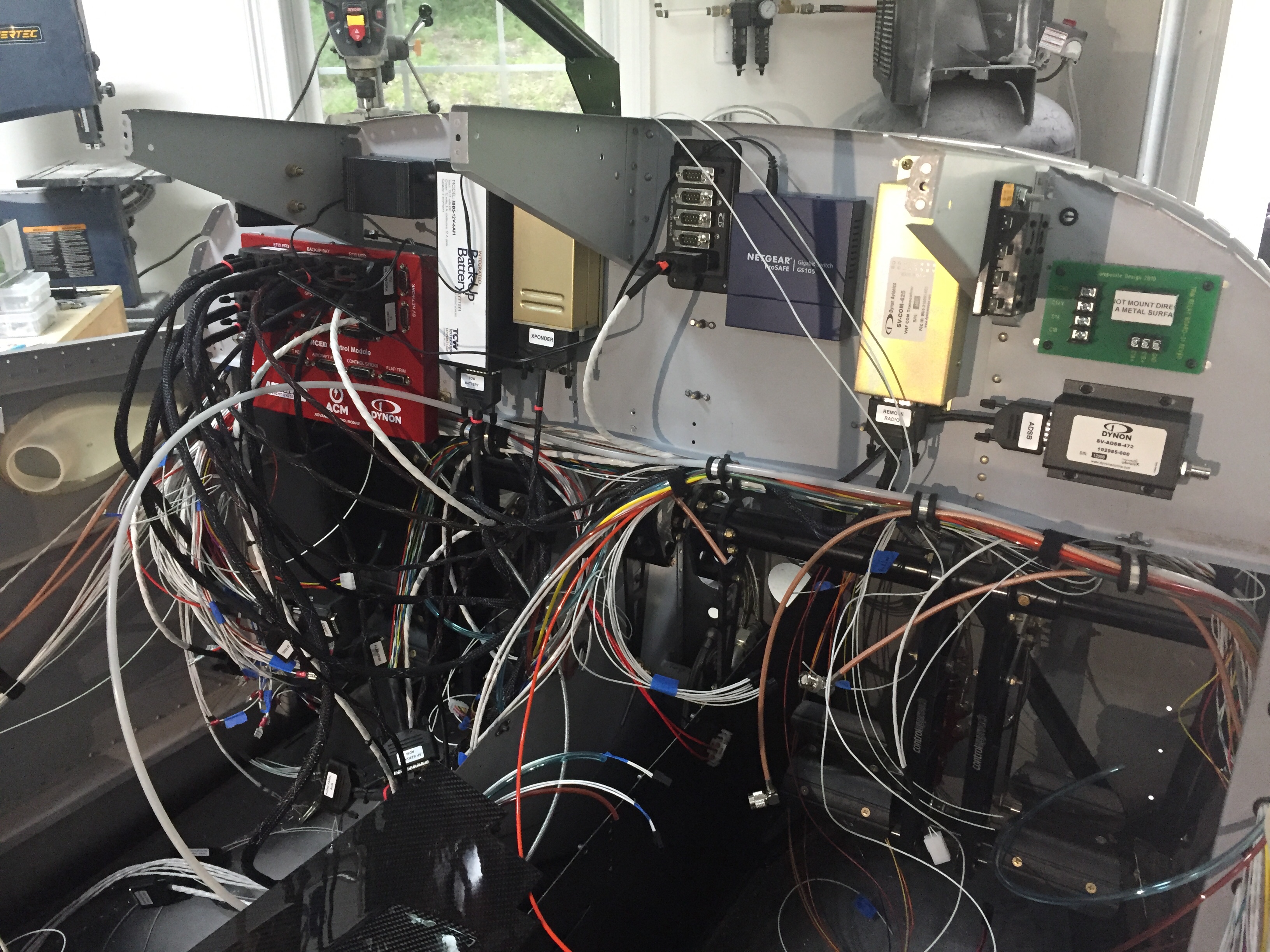
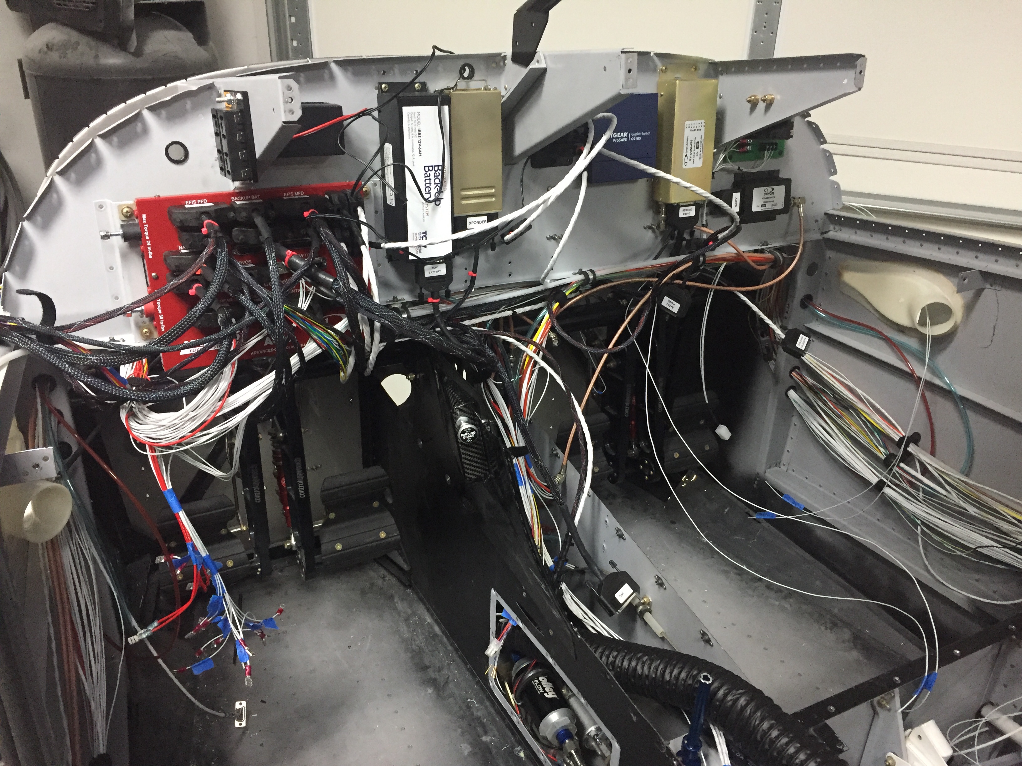
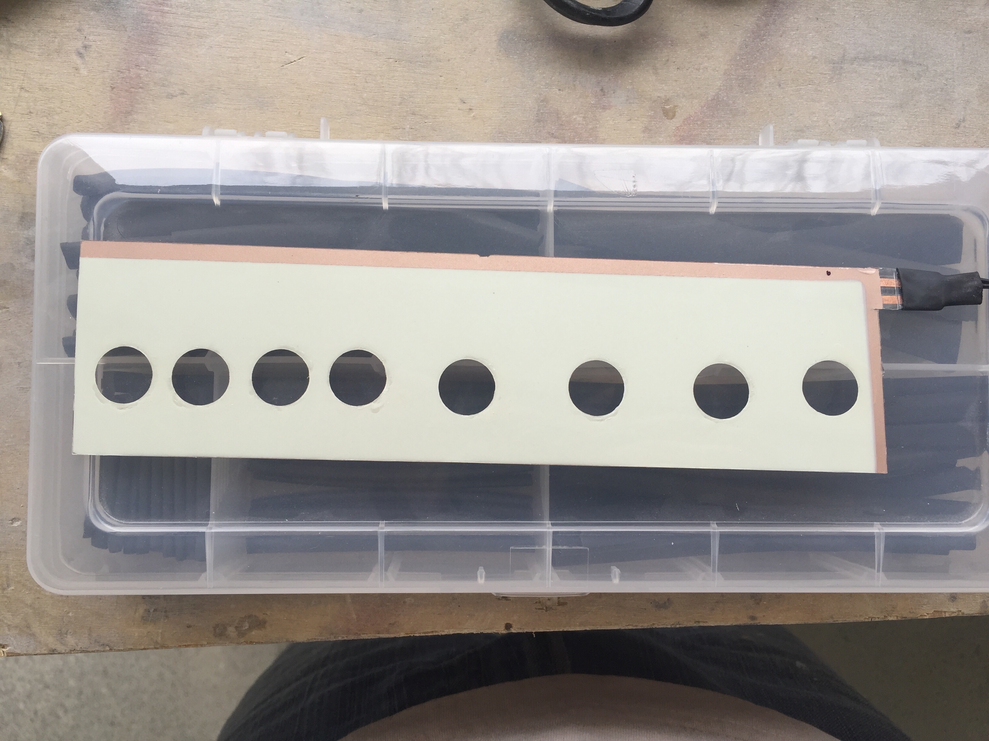
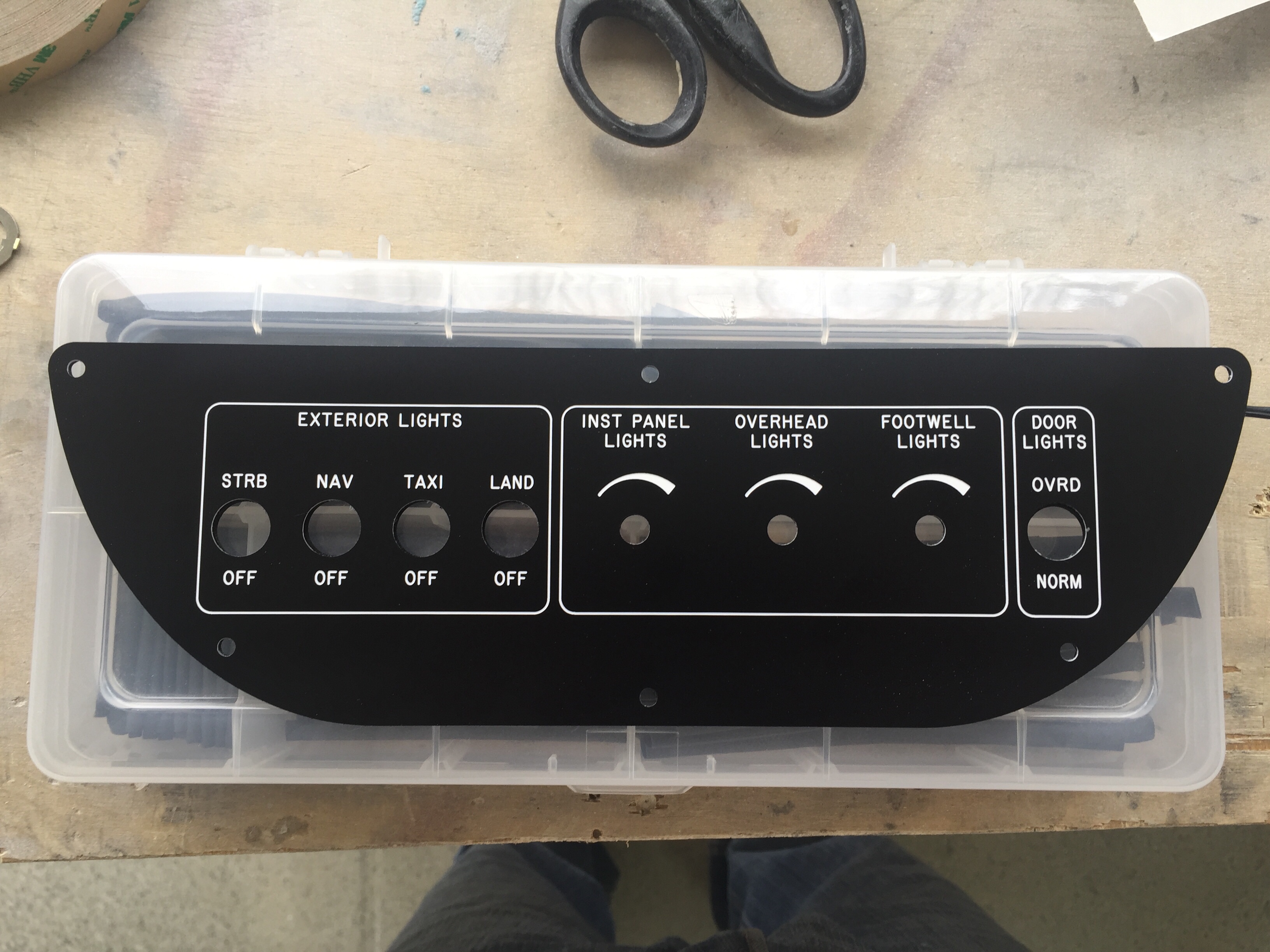
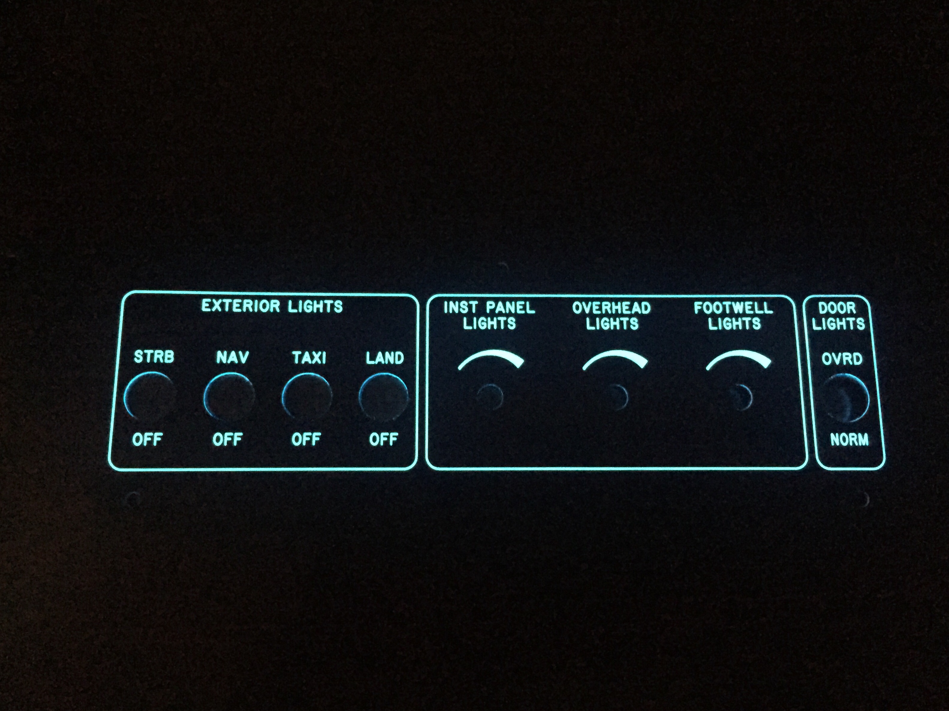
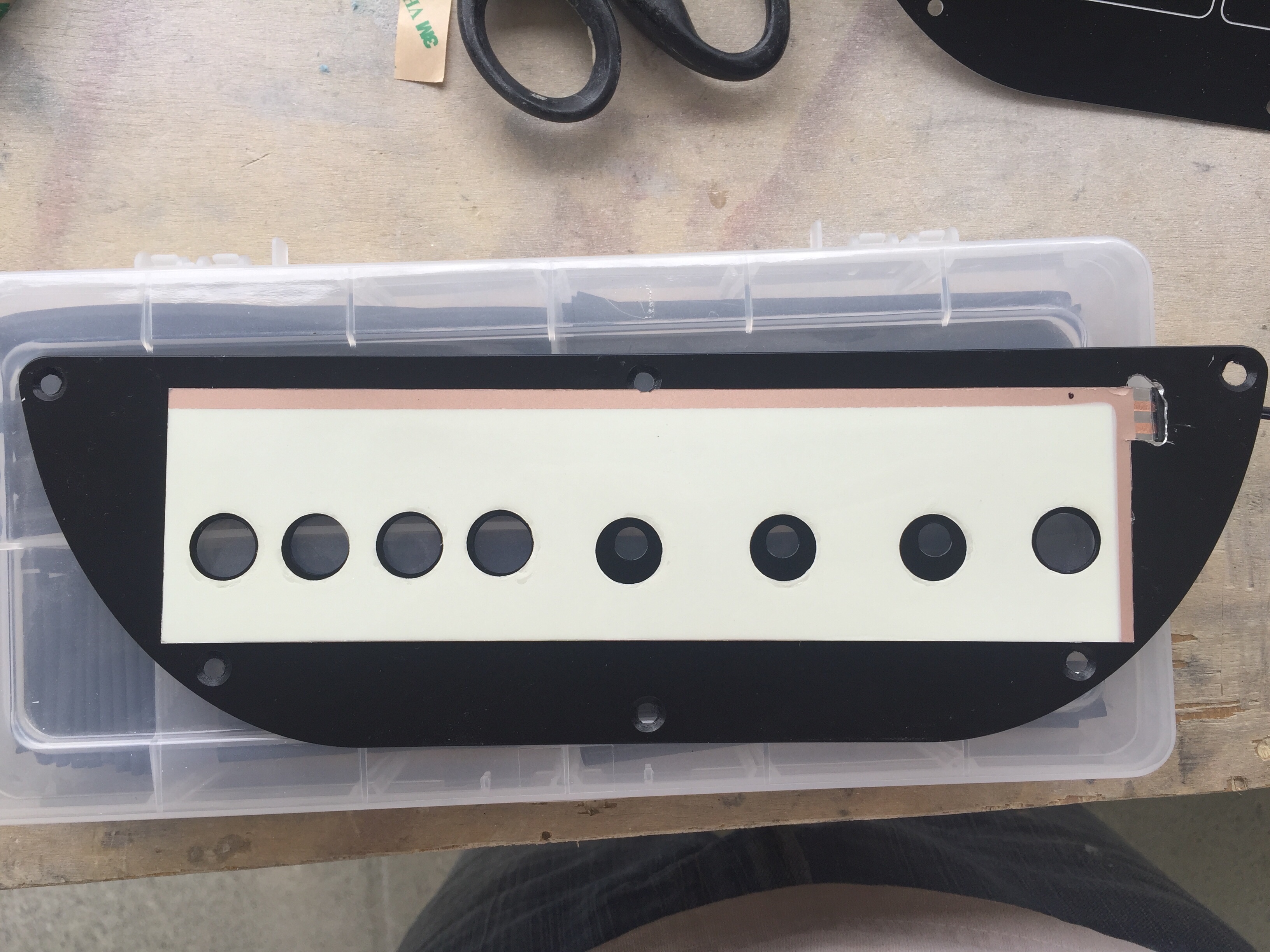
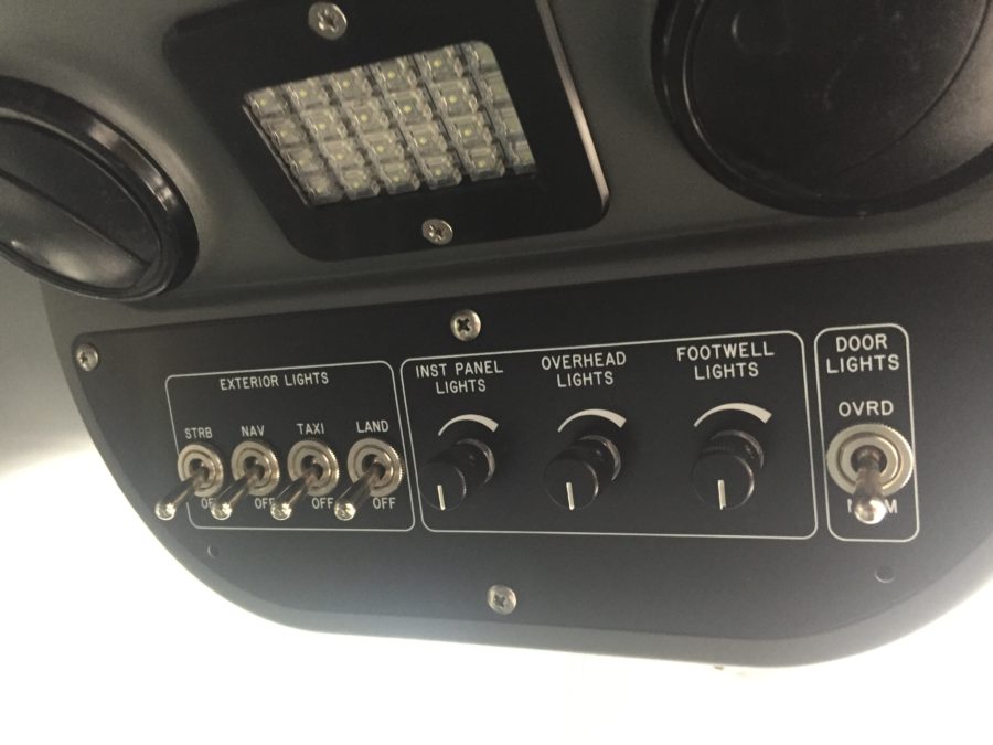
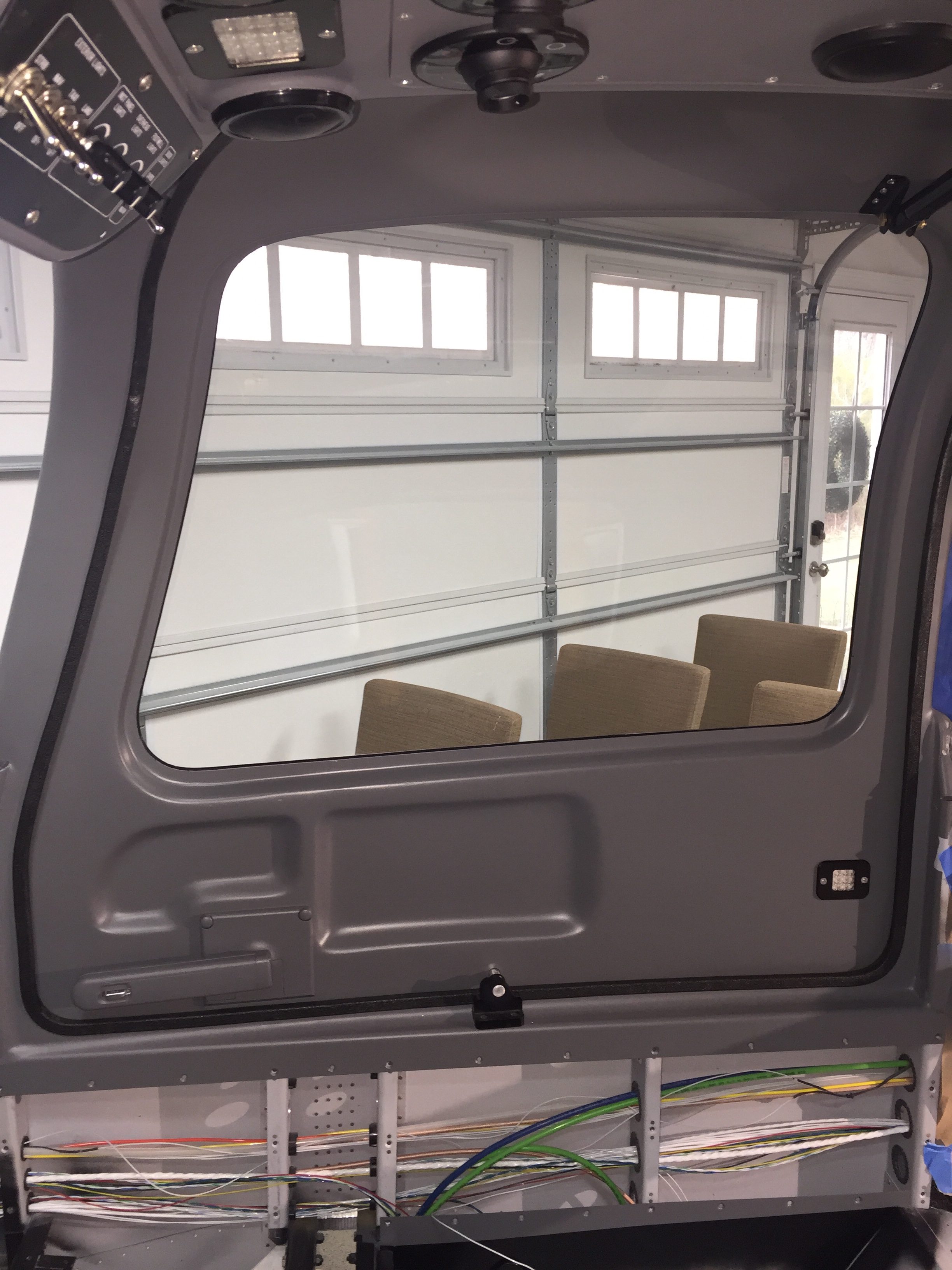
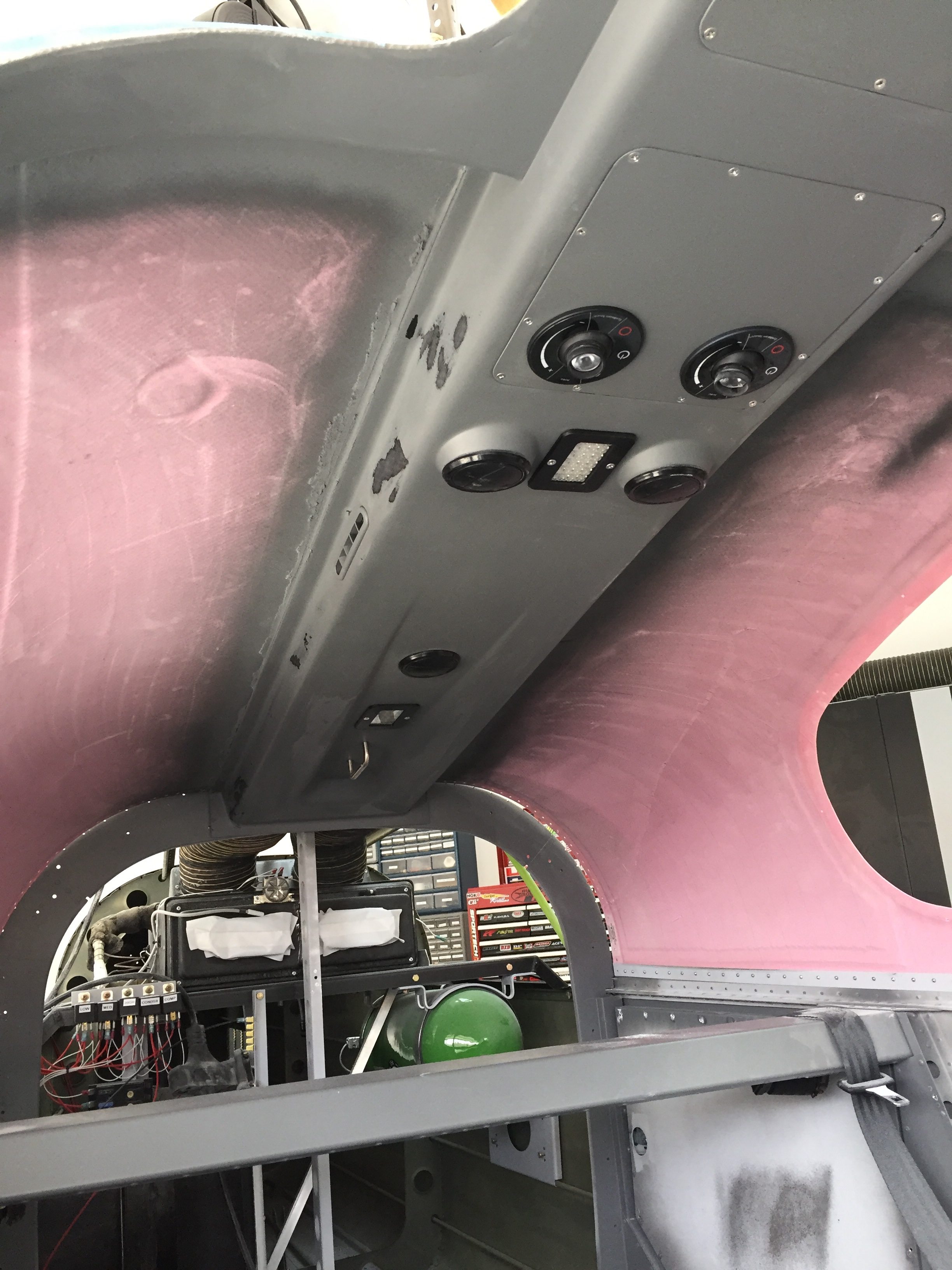
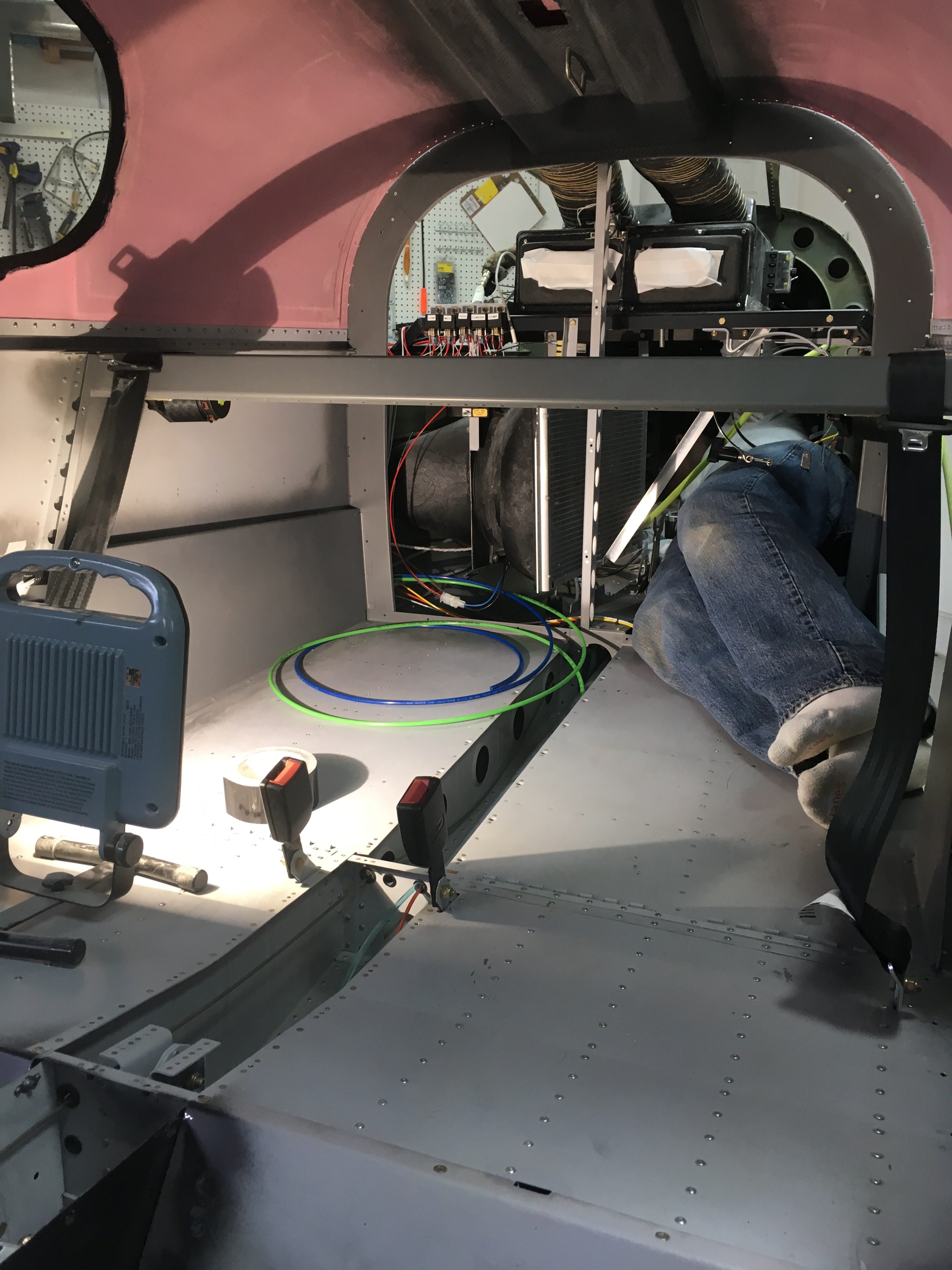
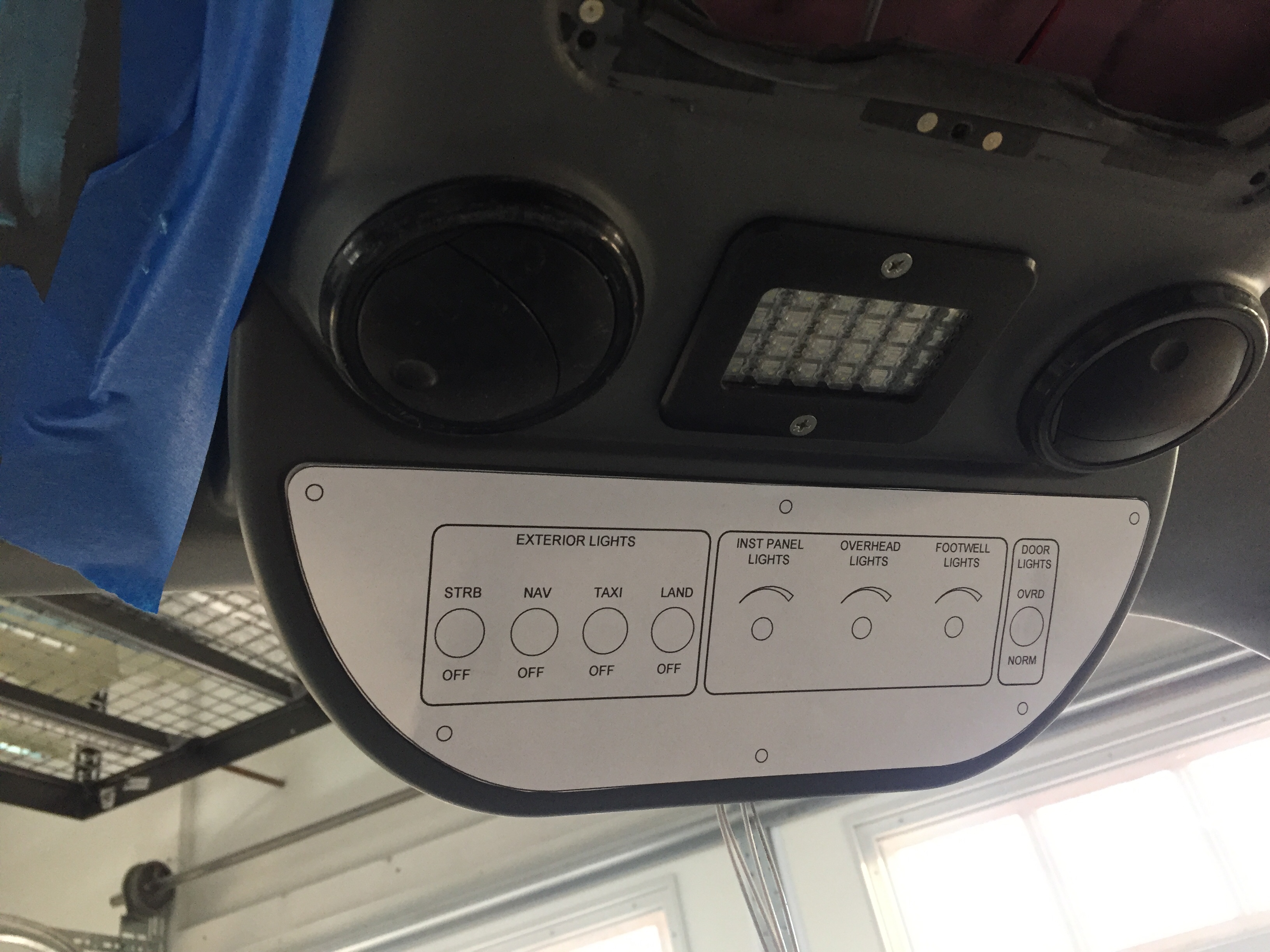
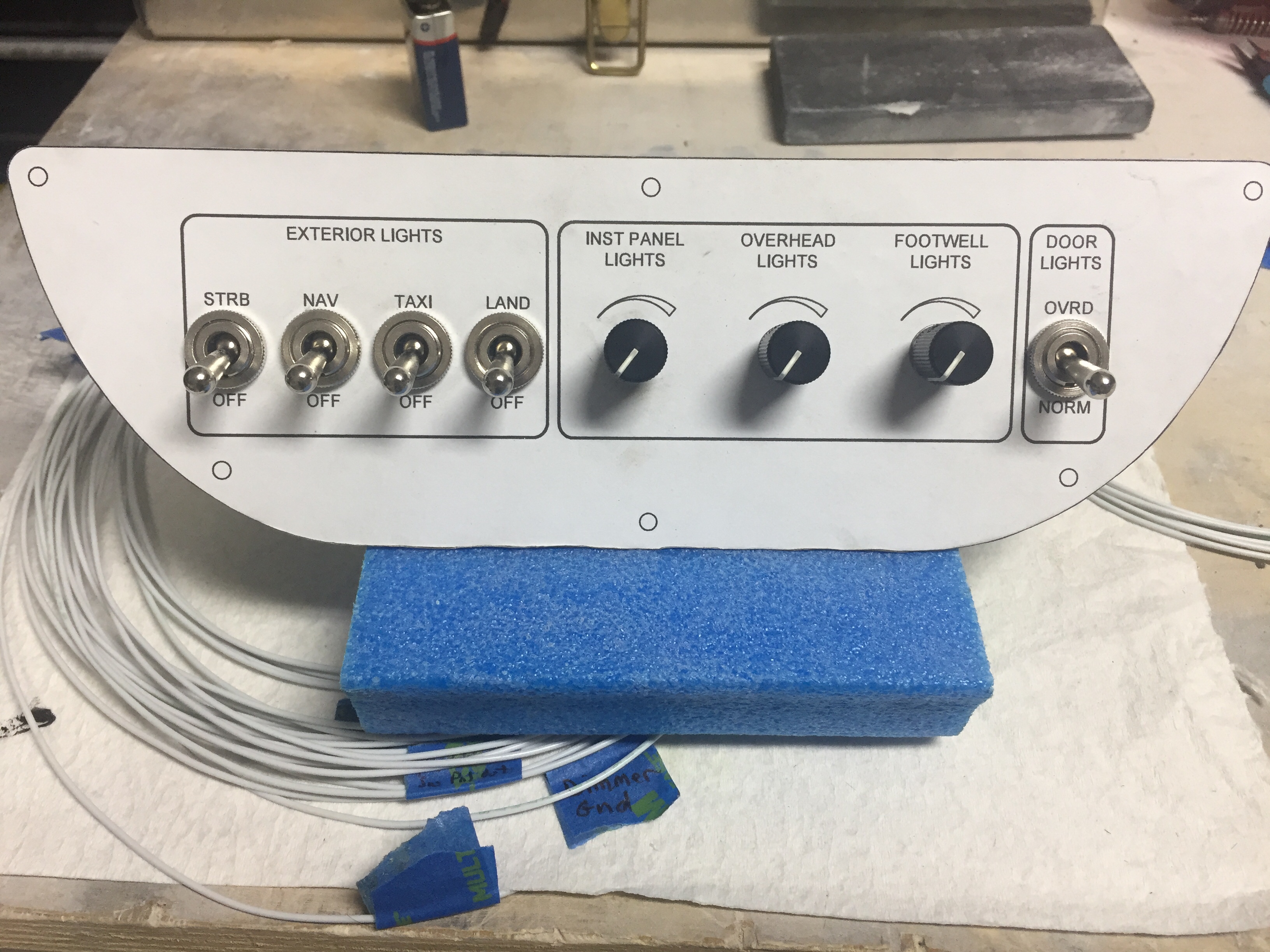
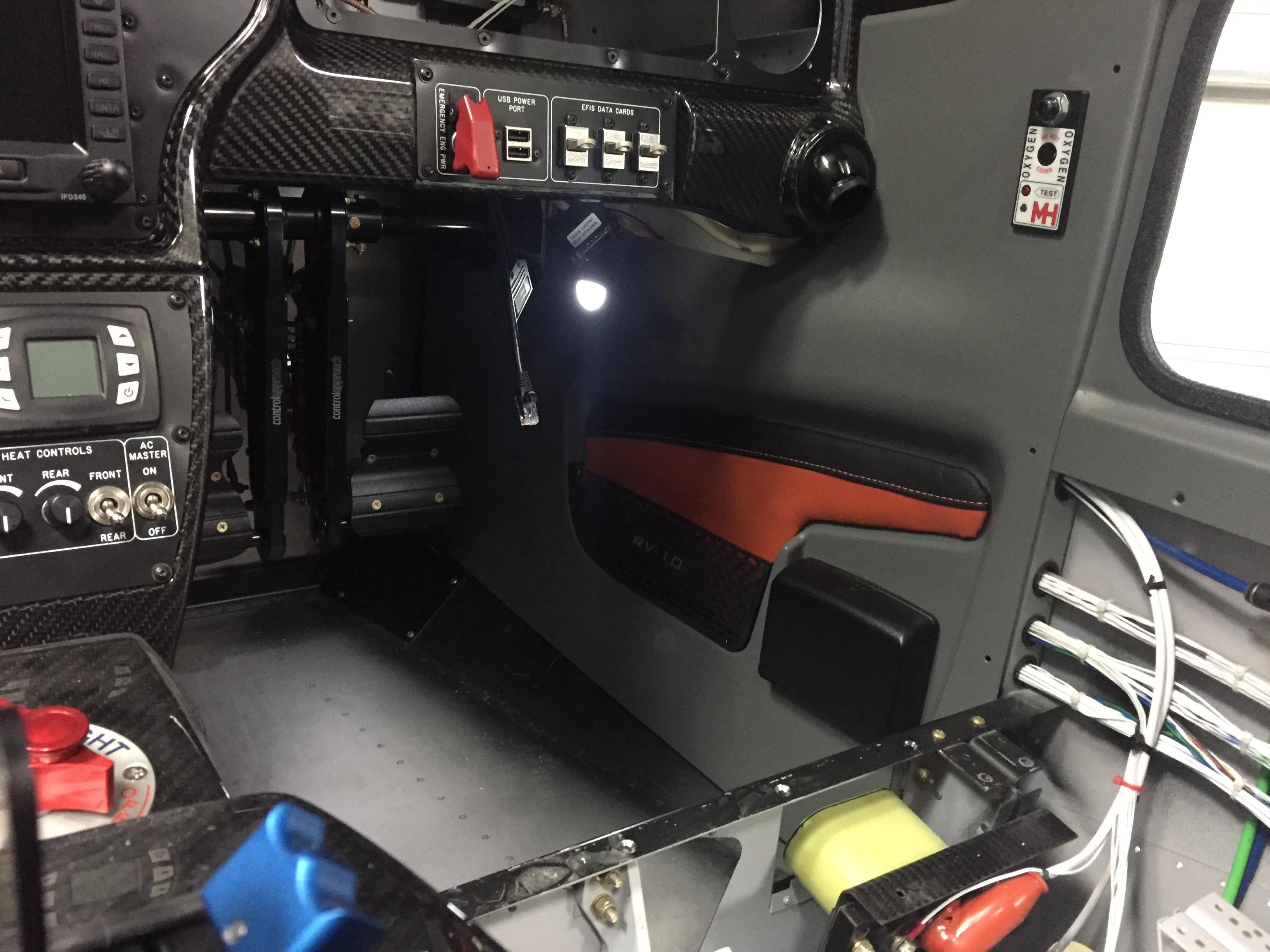
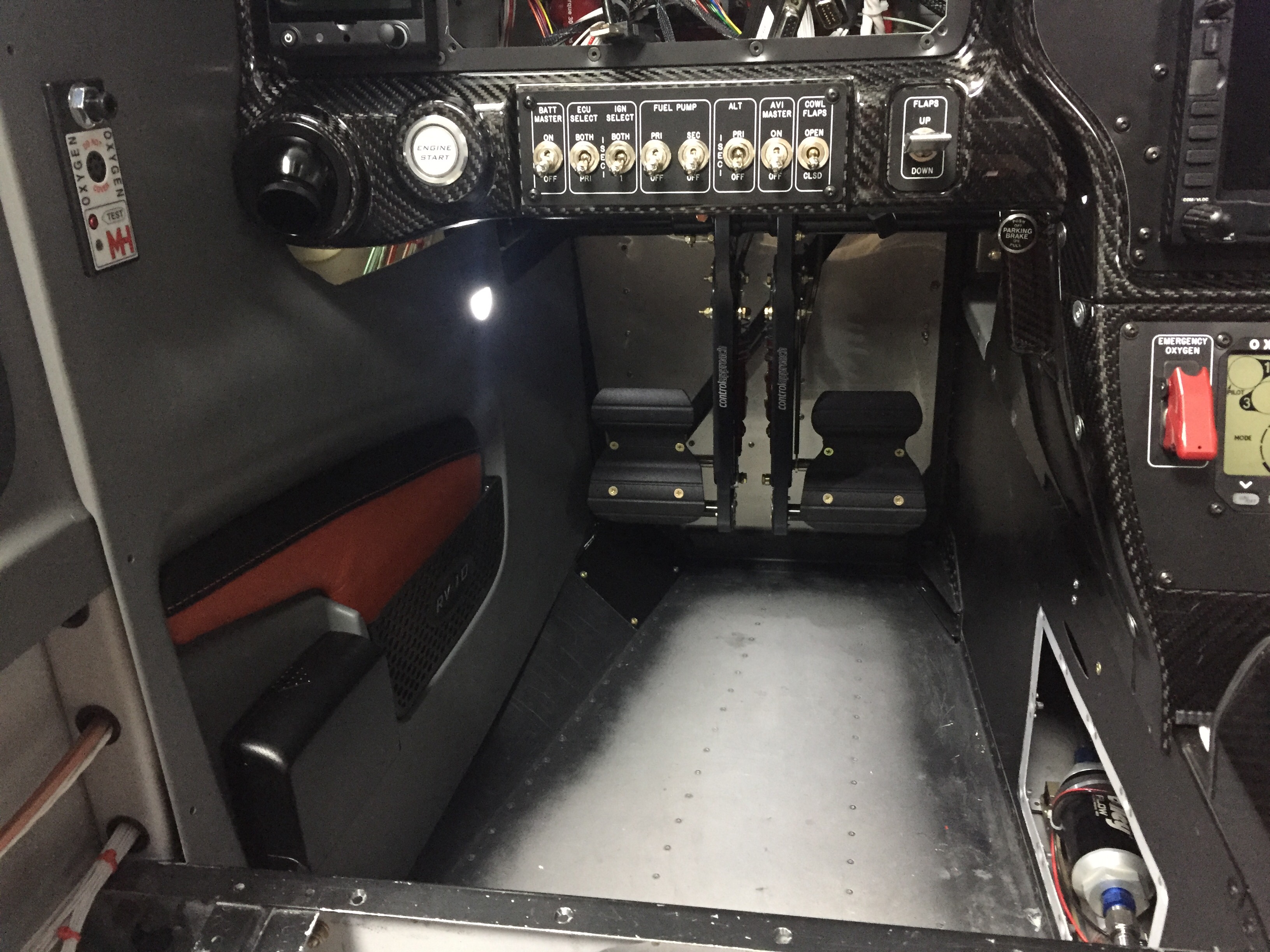
Adding even more color, I finished up the last of the wire bundling on the cabin sidewalls and went ahead installing the side panels with leather inserts.  They had been trimmed and painted for some time but I held off pulling them in and out until I knew I was done.  I spoke to Vic Syracuse who will be my DAR for airworthiness inspection prior to putting these in, as I wasn’t sure how open he wanted the airplane.  He advised to have it essentially flight ready except for rear pax tunnel cover (to inspect the elevator bell crank), cowling, and tunnel access panel.  This is the first time I’ve hooked up the foot well lights and I’m really pleased with the amount of light they give off.  It’s just enough for convenience while not quite enough to perform surgery on the floorboard.

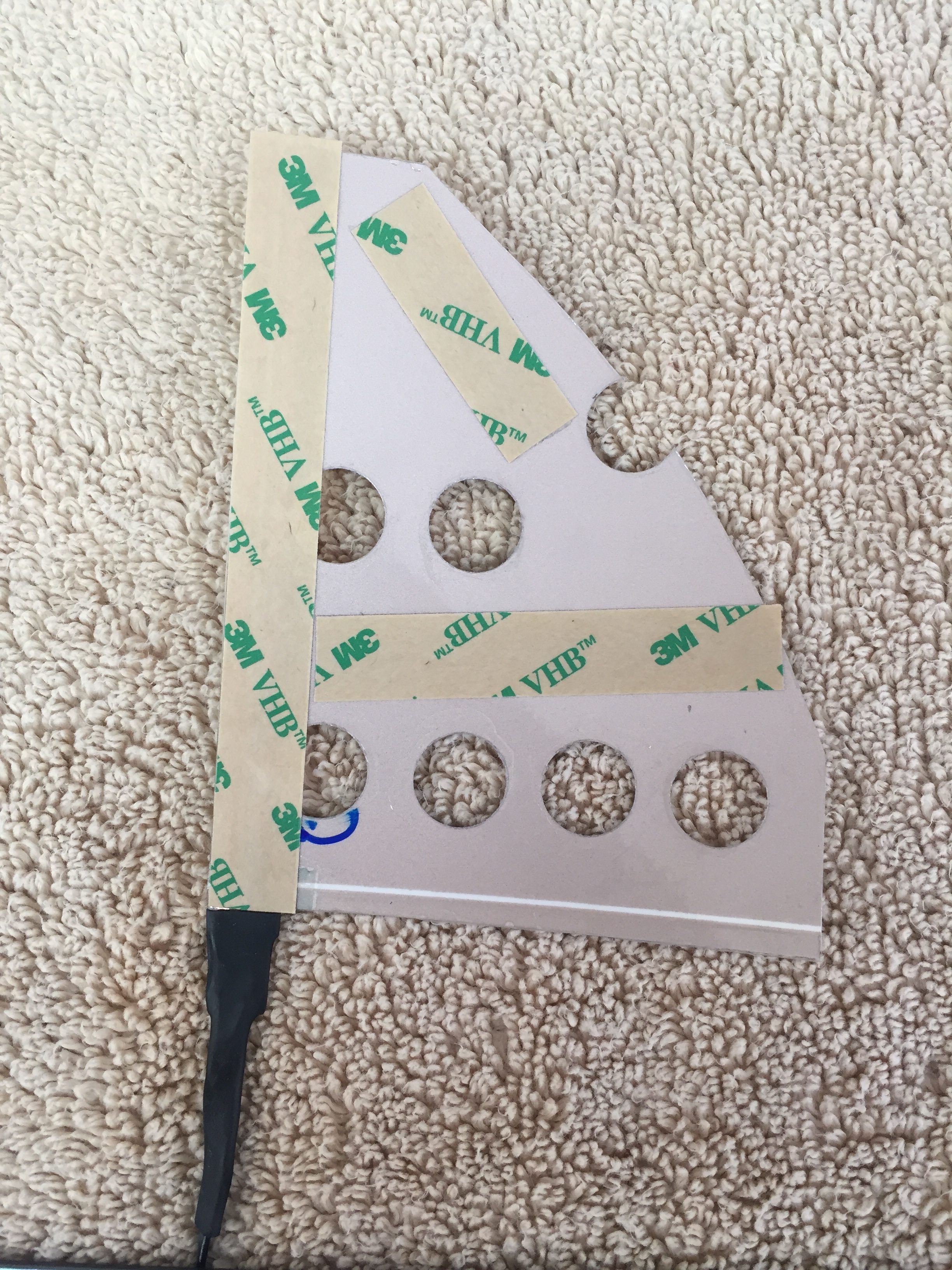
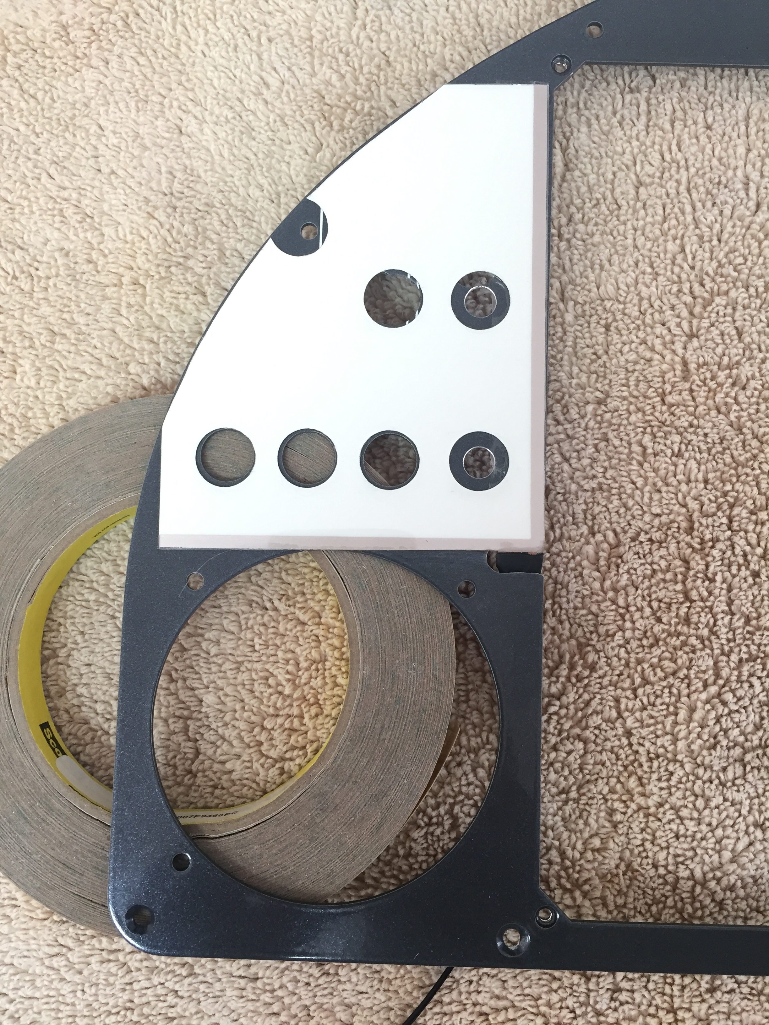
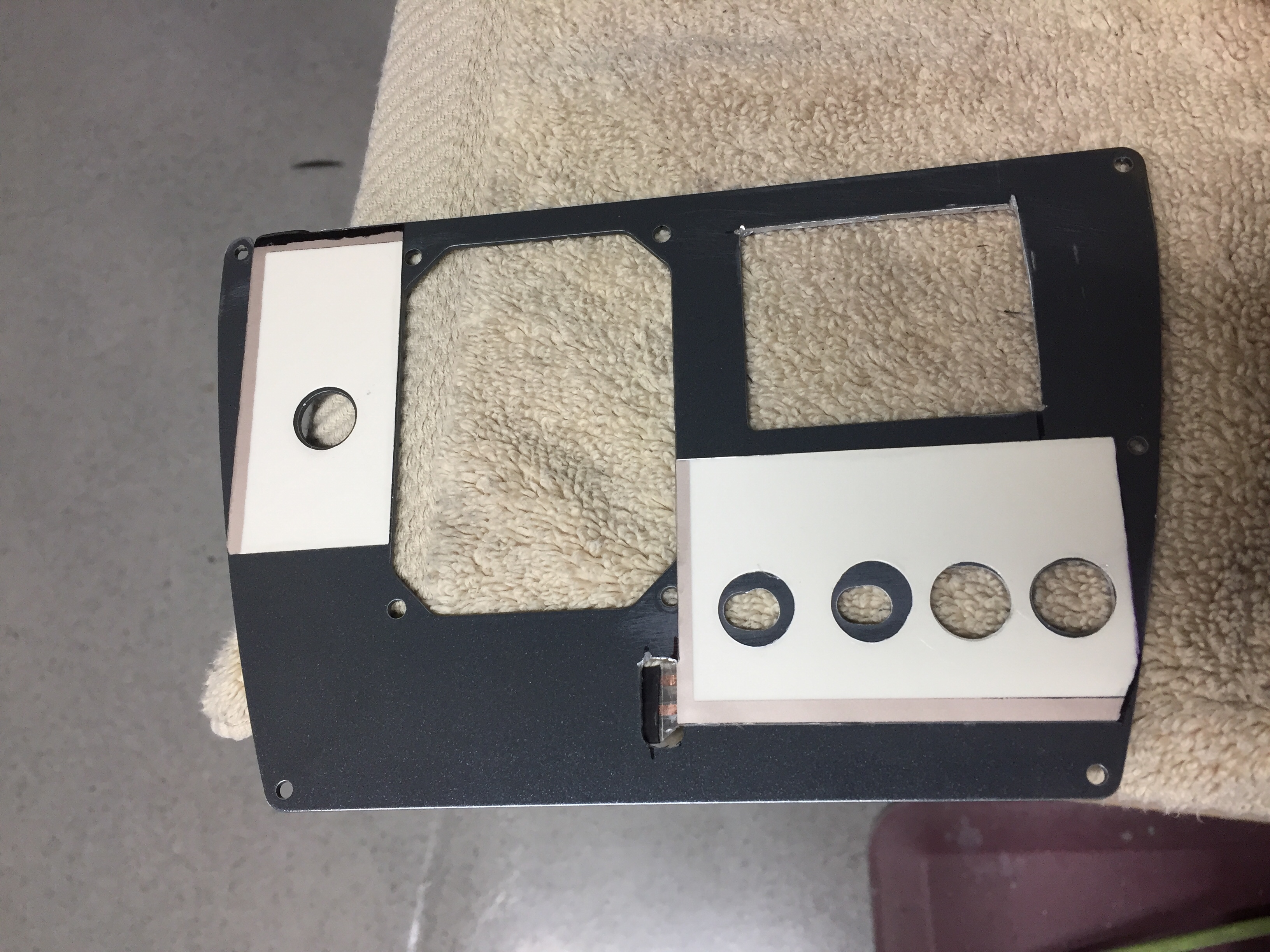
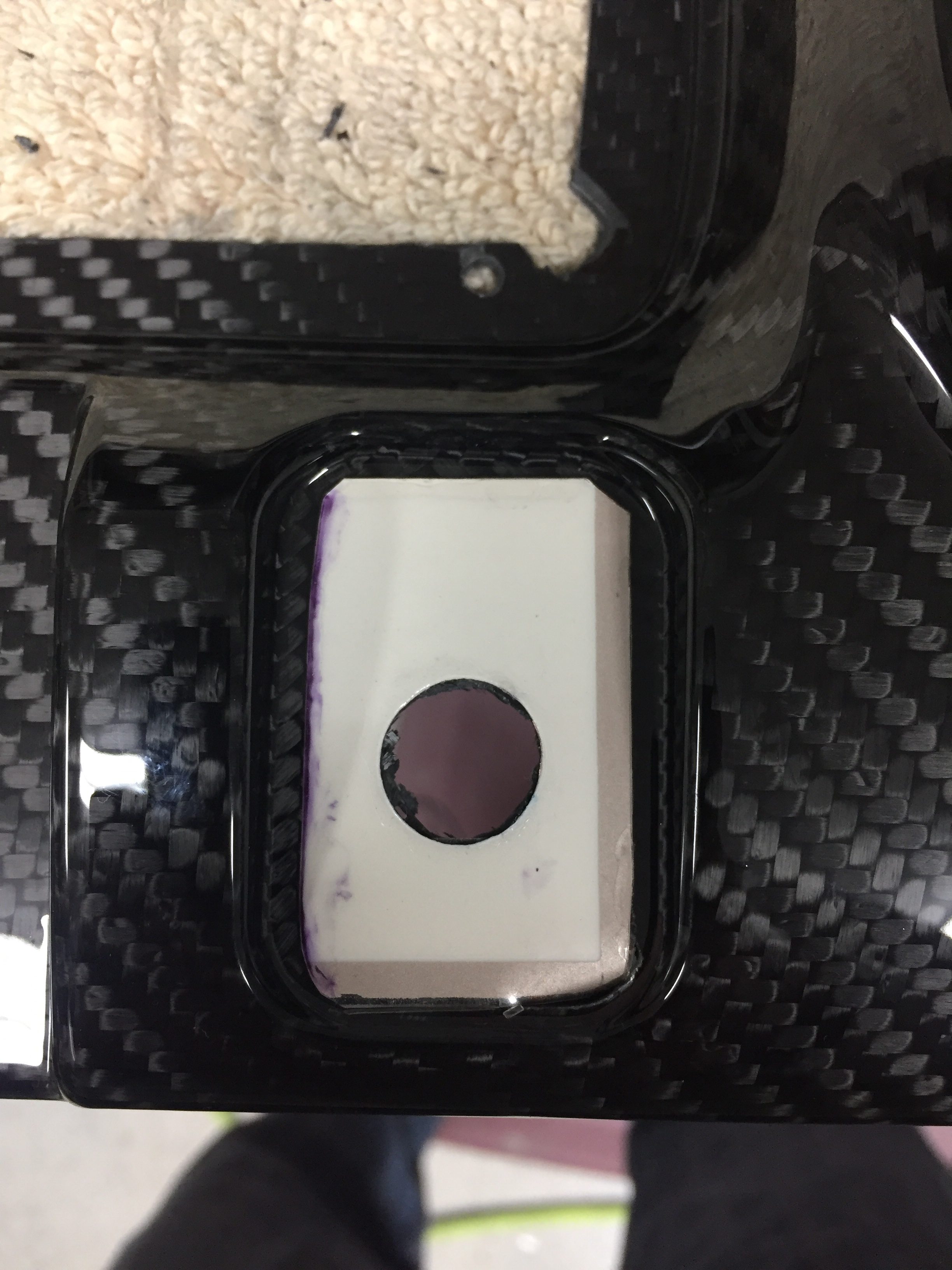
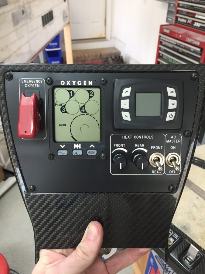
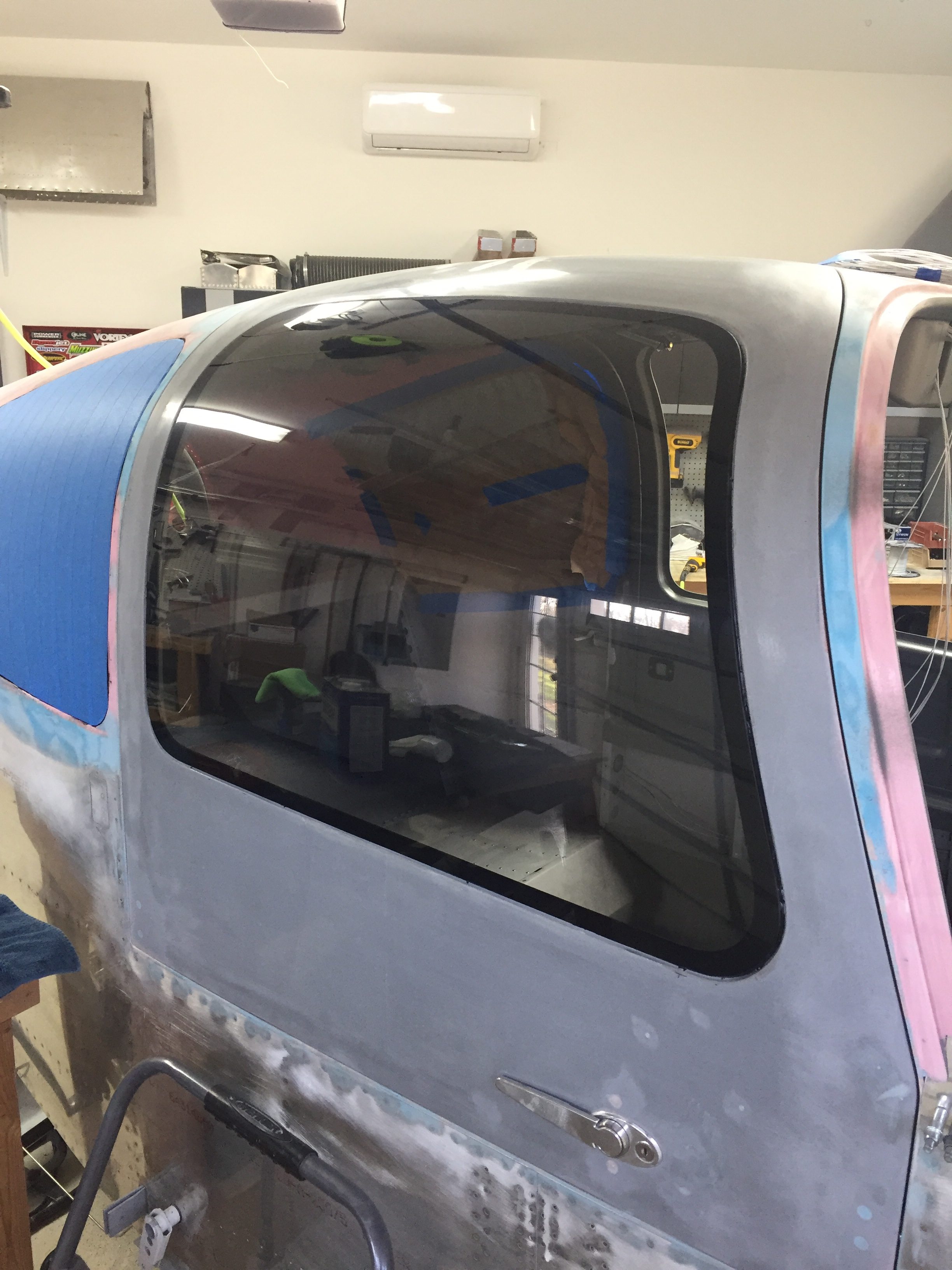
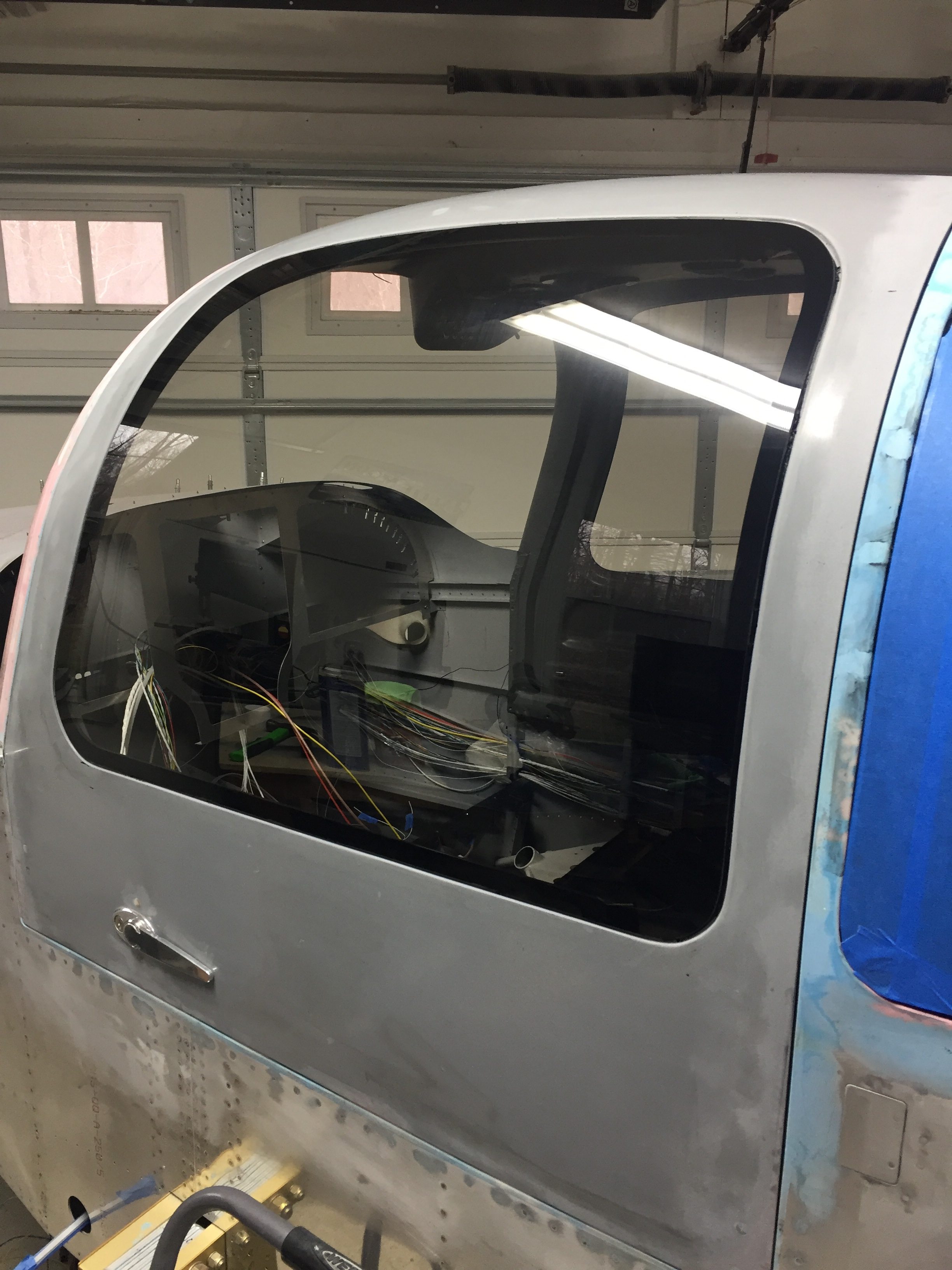
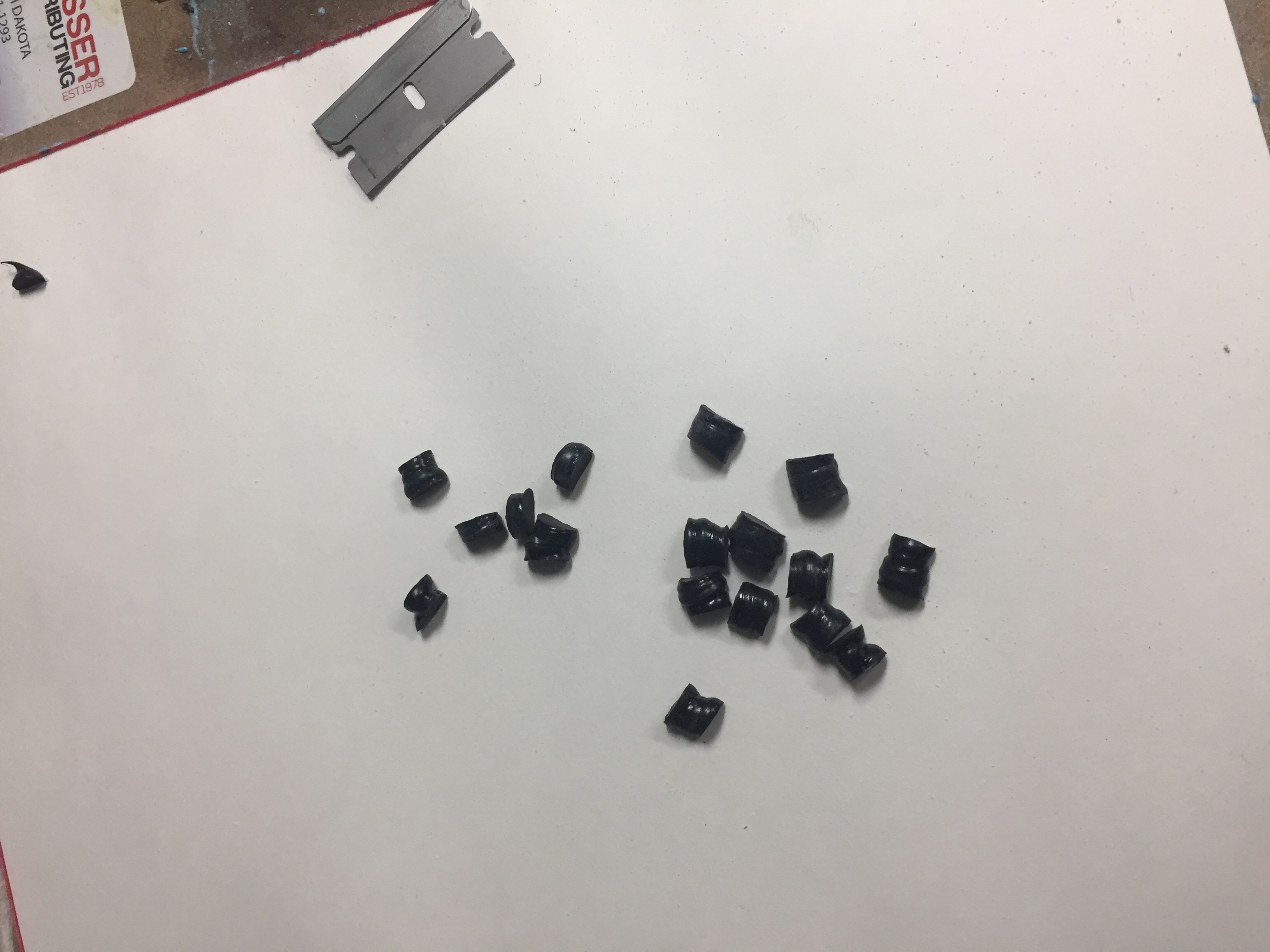
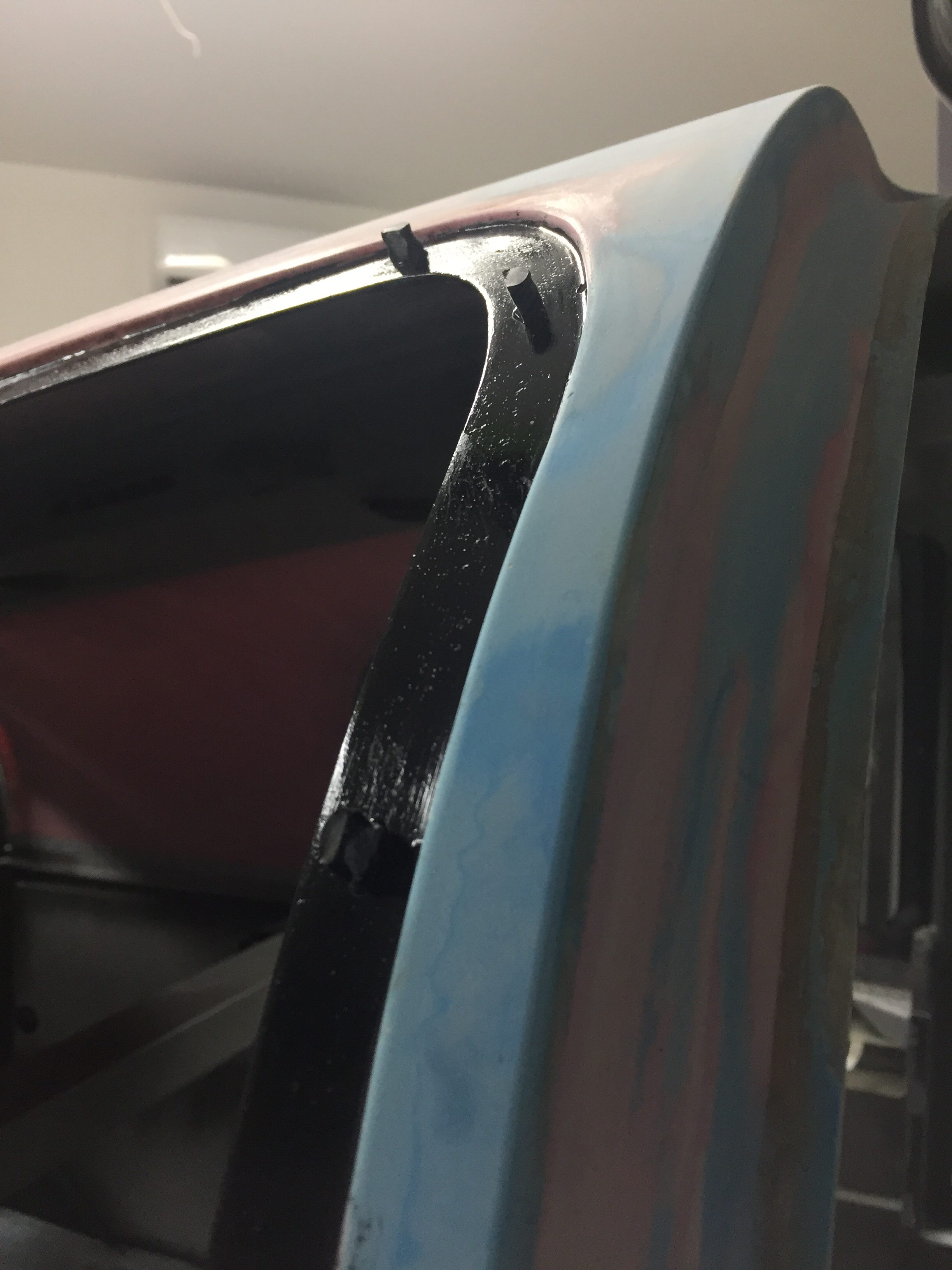
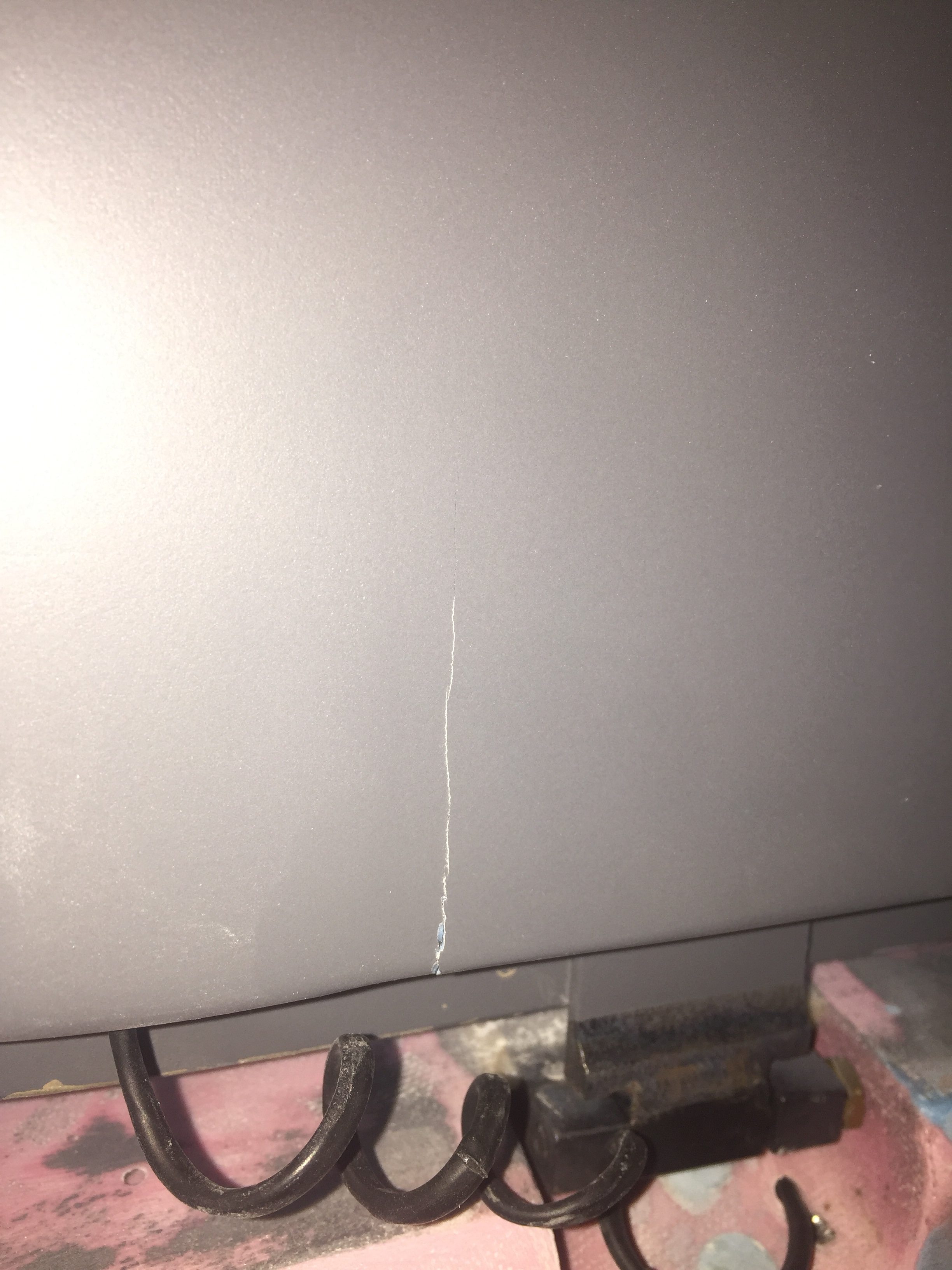
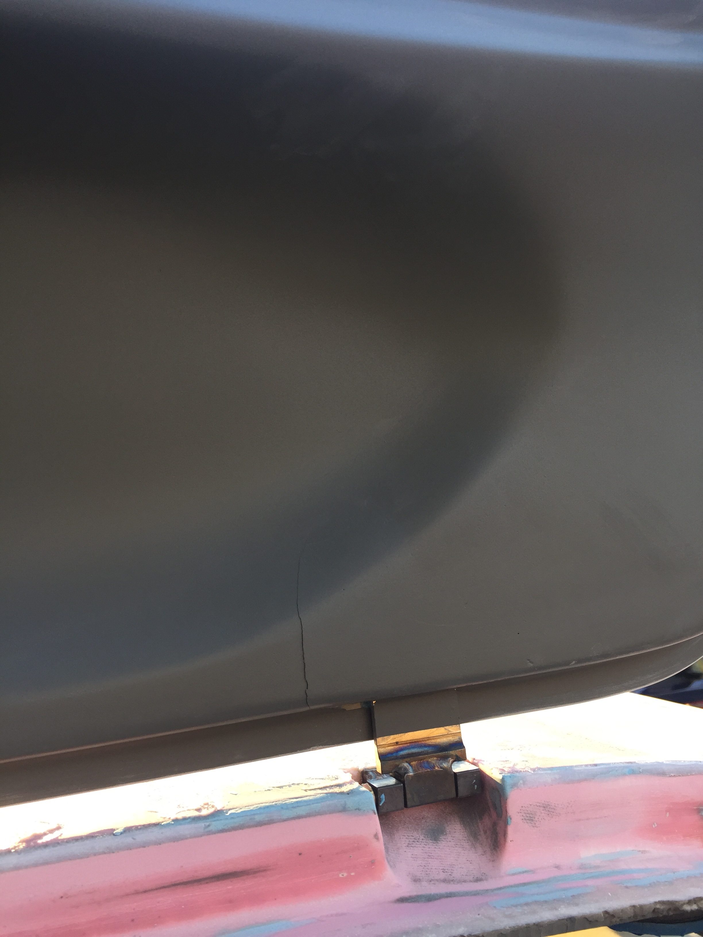
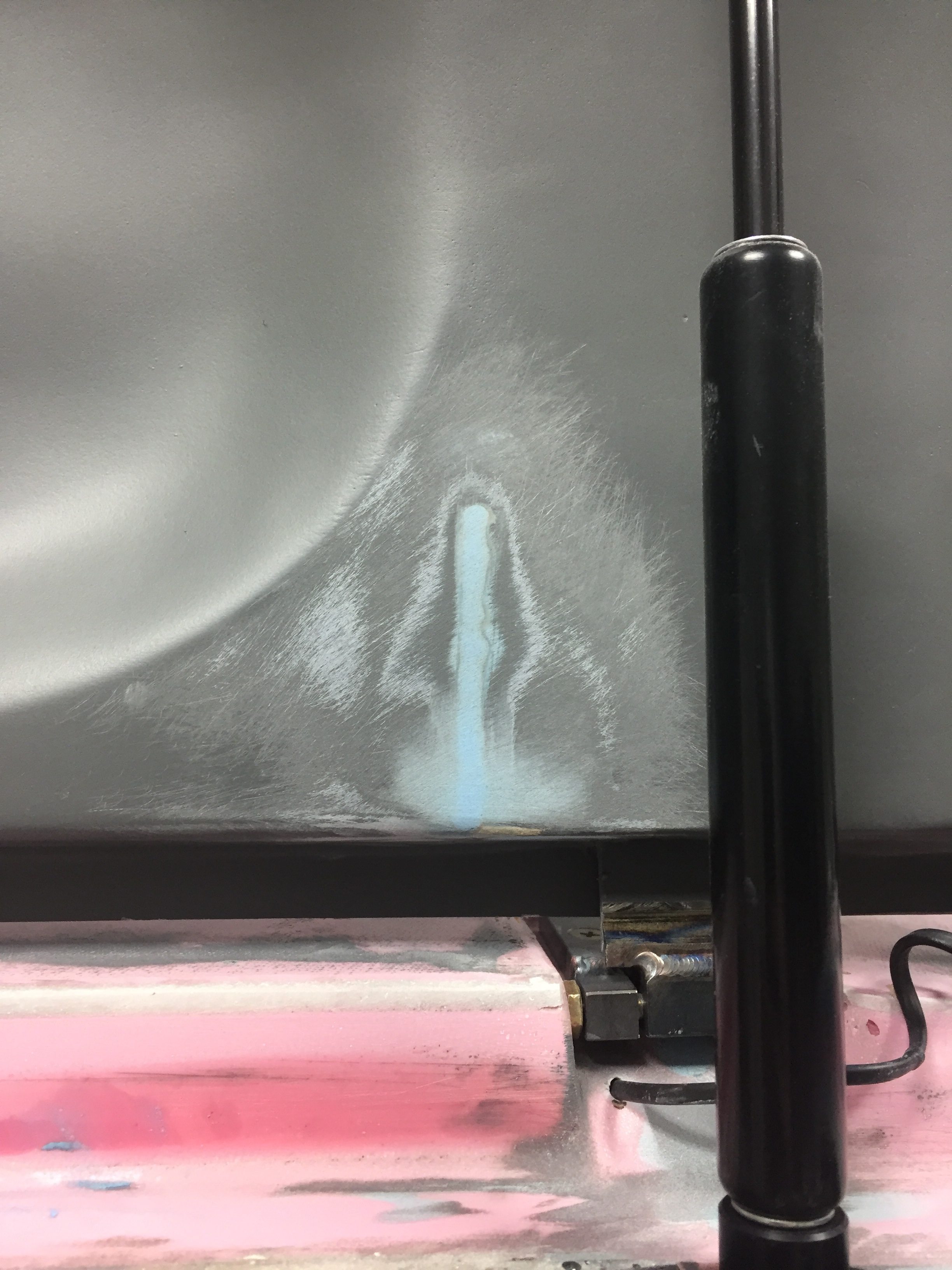
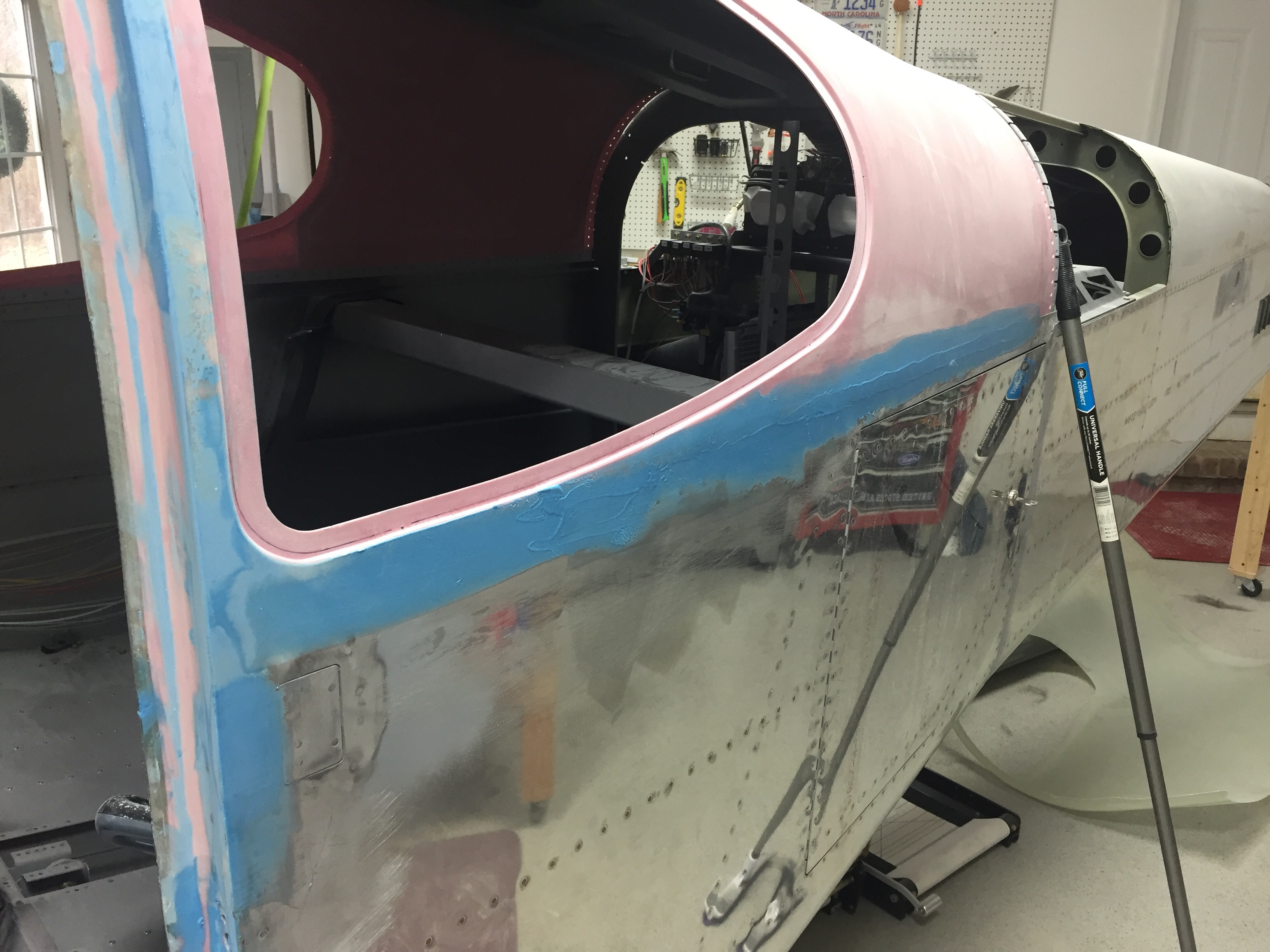
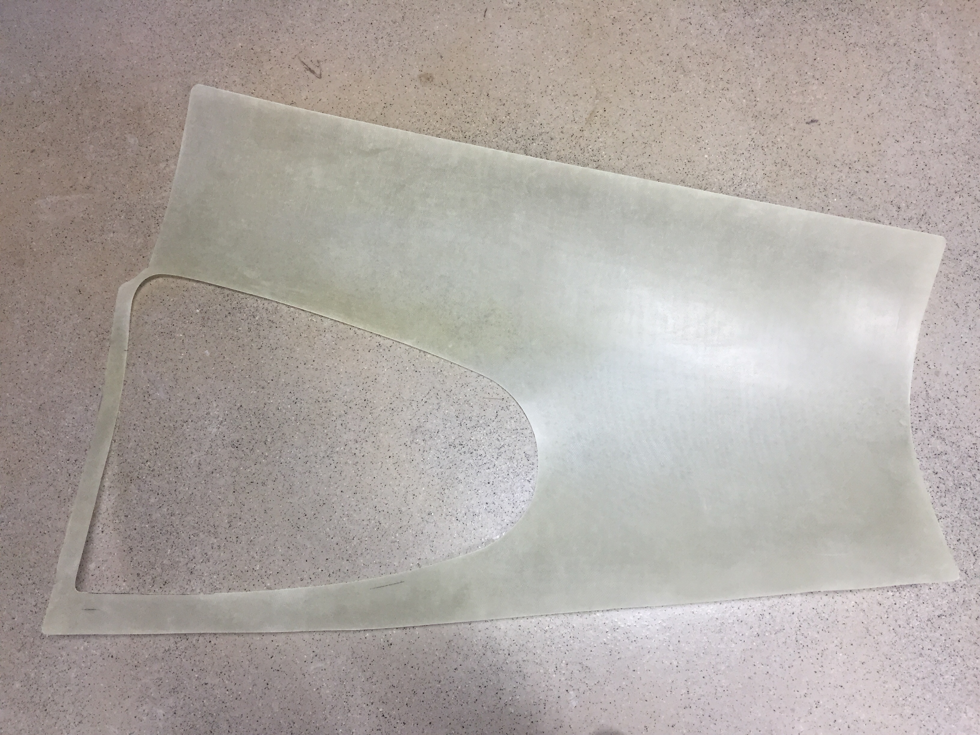
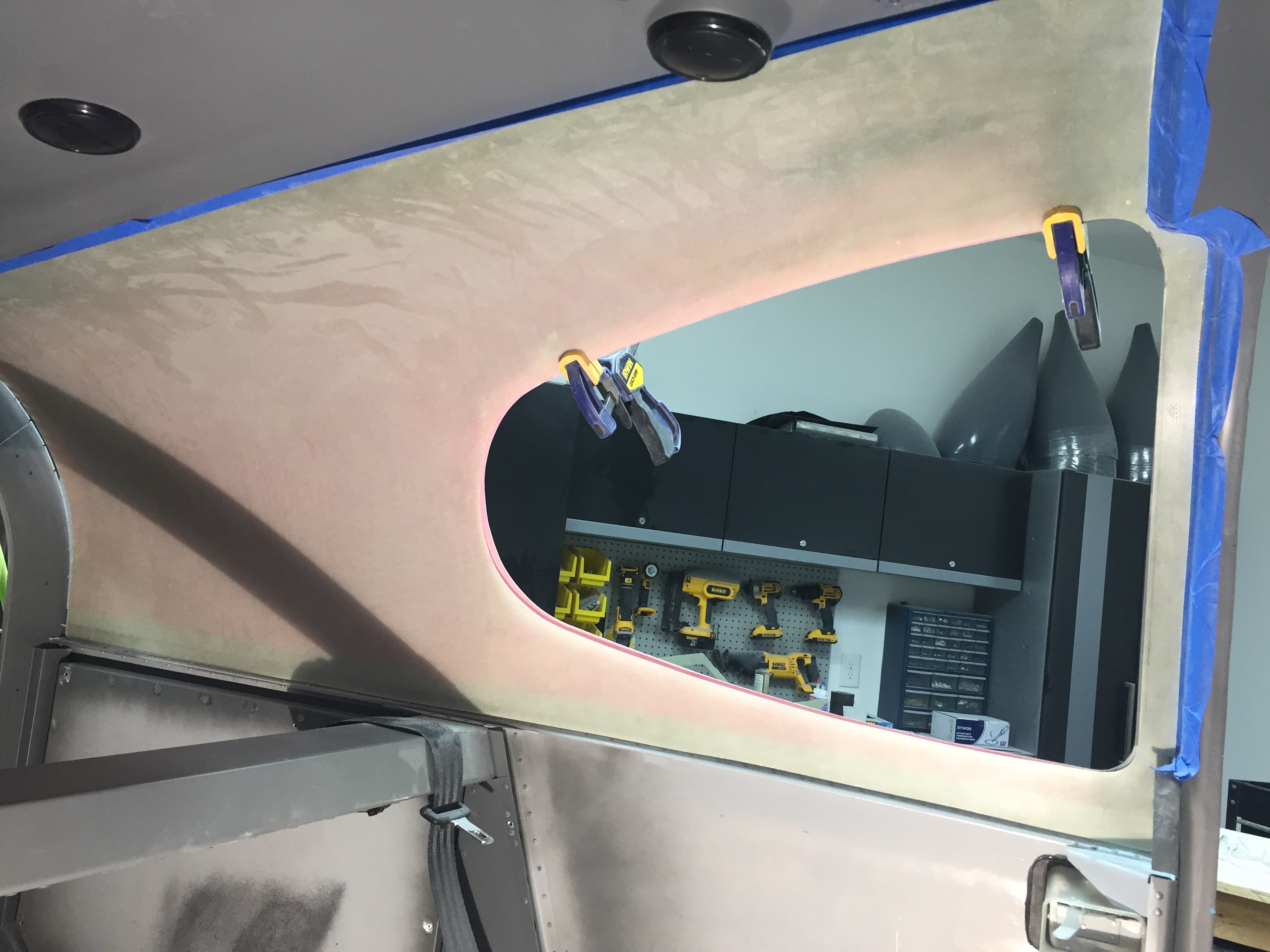
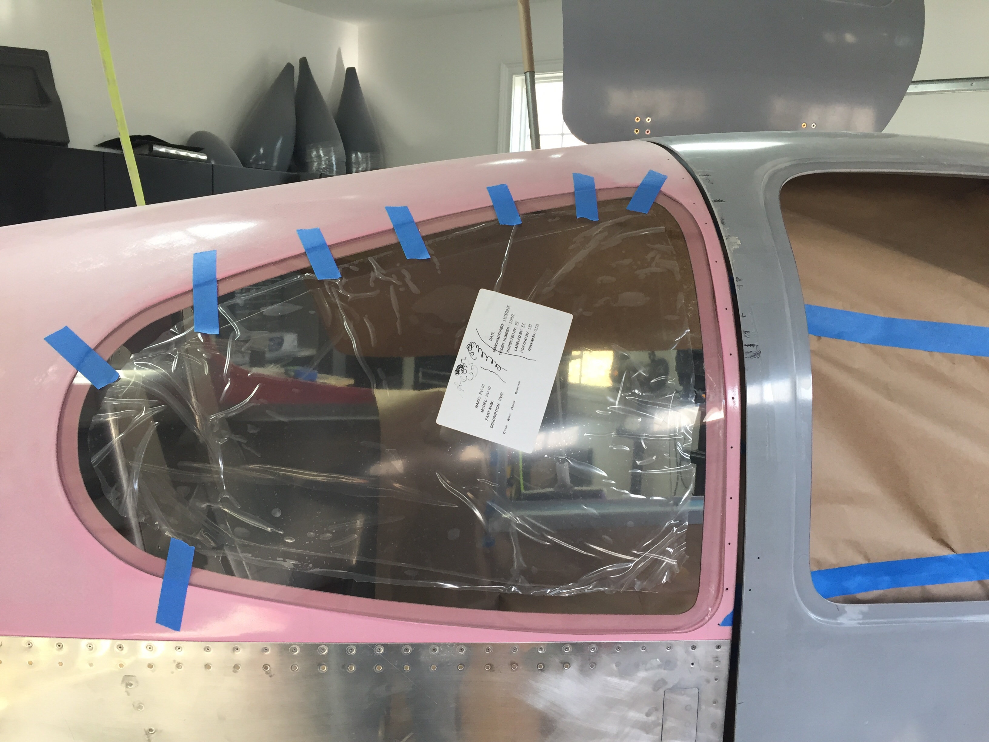
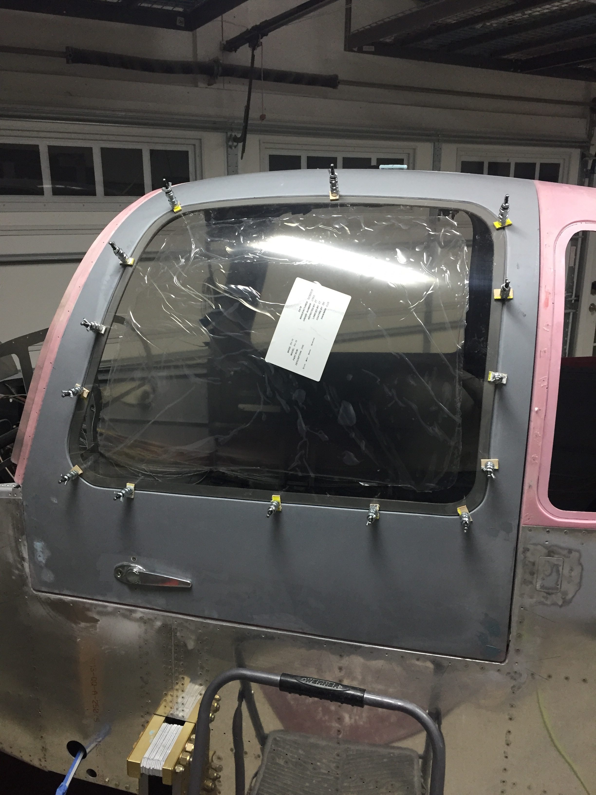
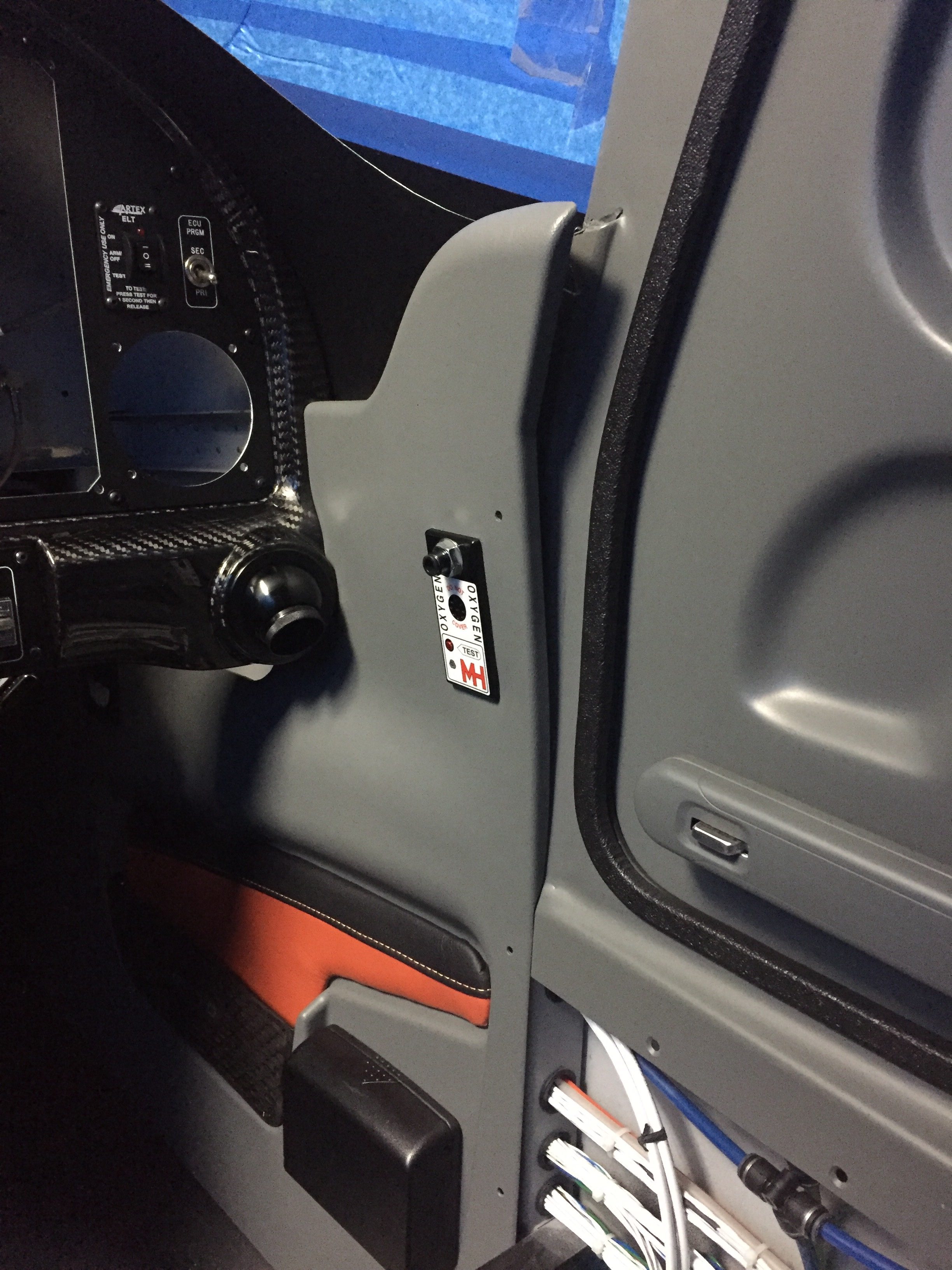
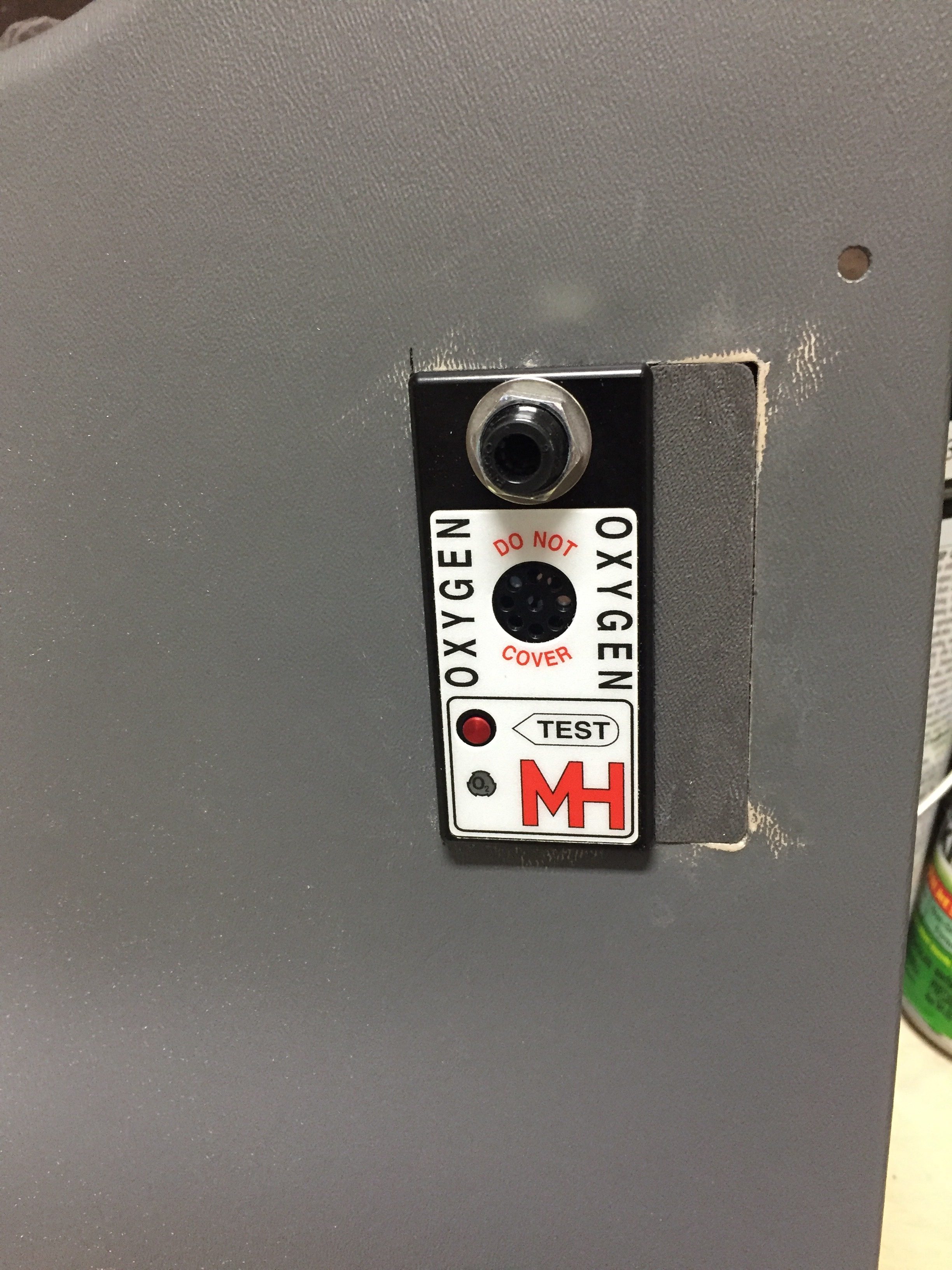
Unfortunately, not all of the gods were looking favorably upon this new addition and when I closed the door, the pins interfered with the oxygen ports, thus not allowing the doors to latch properly.  Turns out I have the ports ½” too close to the door frame.  Darn.  Well, I said, a lot more than that and maybe one or tools took flight across the garage with no lasting damage.  My blood pressure through the roof due to my ignorance and stupidity of not being mindful to this interference, I weighed the options of replacing $500 panels or coming up with a patch.  I can’t make the pins shorter since they wouldn’t function correctly with the Plane Around latch mechanism.  I had already had to glue a piece on the pilot side panel and reinforce it with a bit of epoxy.  The seam was easily hidden and paint covered everything, so I was hopeful I could repeat the process.  A call to Will at Aerosport Products equaled a few scrap pieces of plastic heading my way.  An evening of creating two patches and a bit of filler, and I’m back on track.  If you look close enough to tell the patch is there, you probably won’t be flying in my airplane again; kindly go away and take your judgement with you.

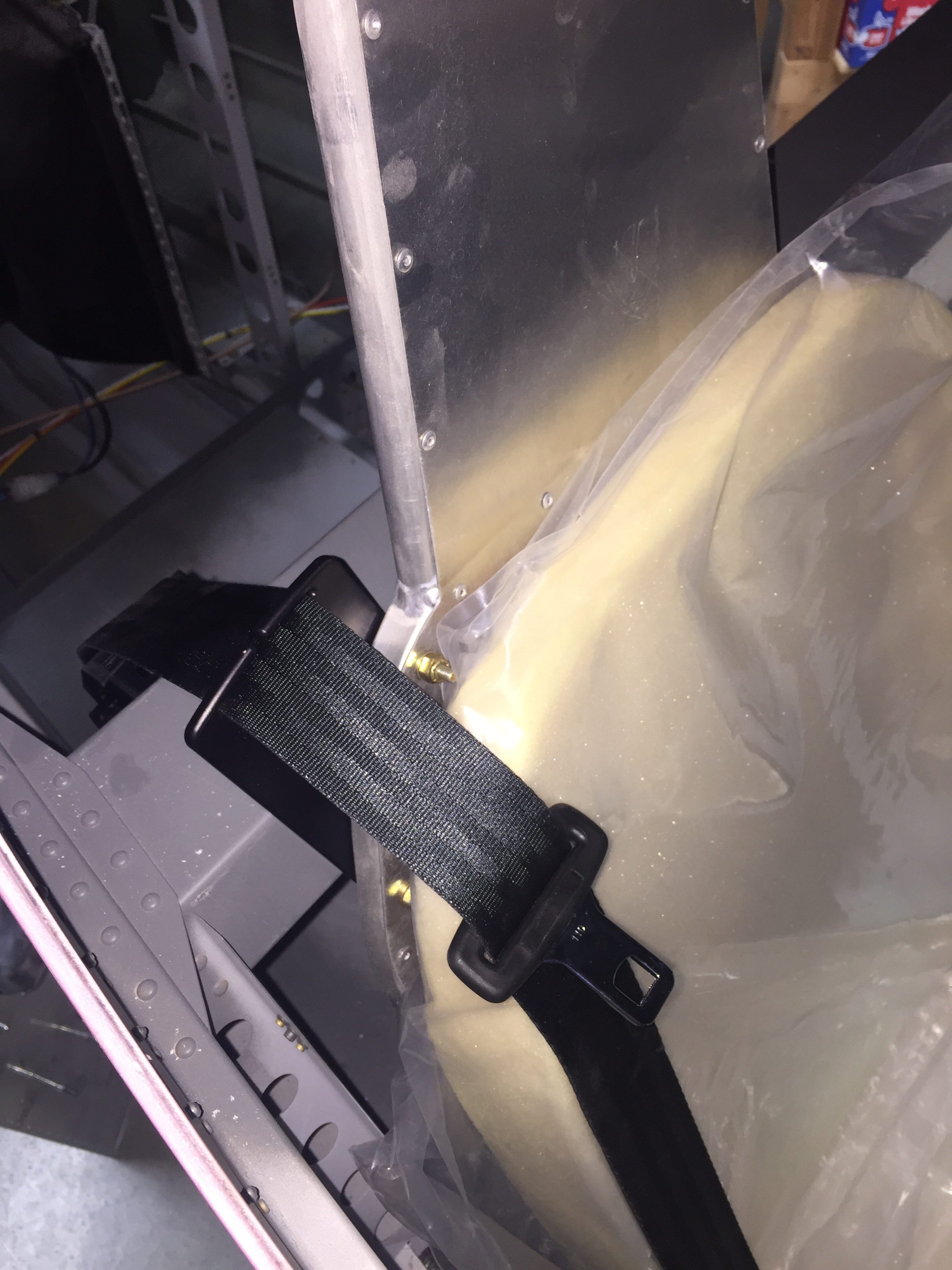
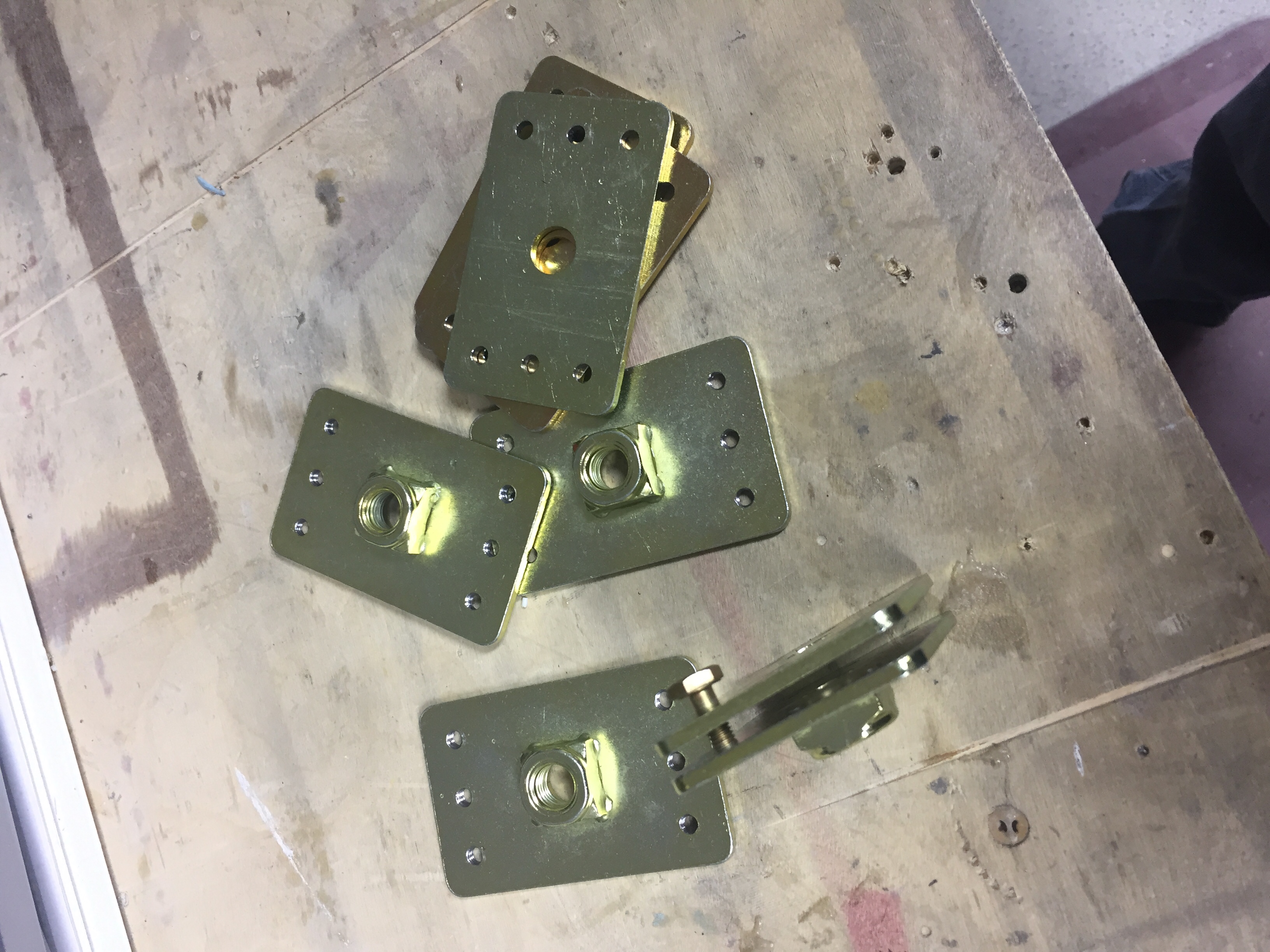
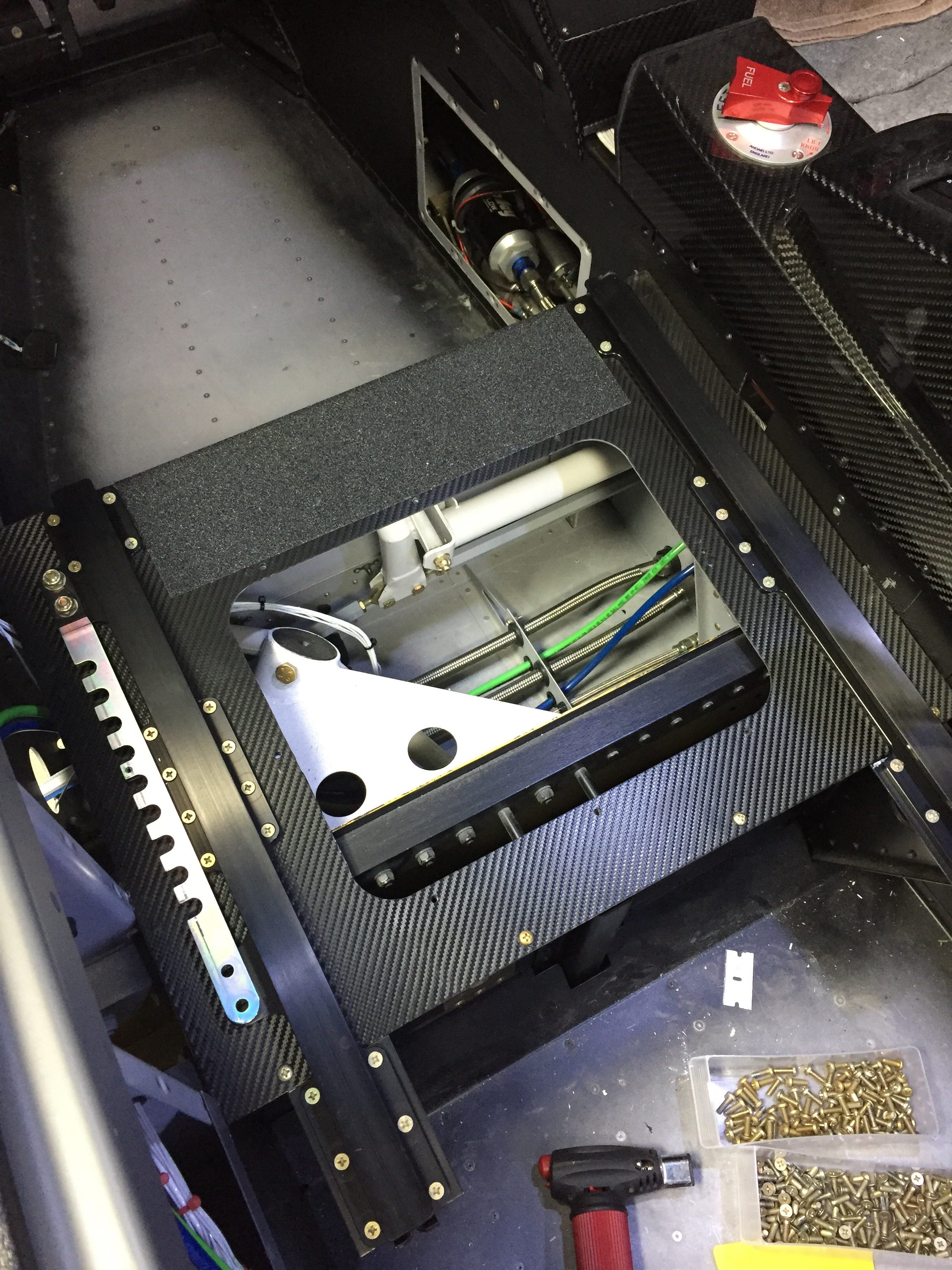
Meanwhile, I applied the 3M carbon vinyl wrap on the seat pans to clean those up.  I figured out quickly paint was not going to hold up there.  Brian and Brandi had great results with the wrap material, so I figured it’s worth a shot.  I then put a strip of anti-skid tape to facilitate stepping on the seat ledge while getting in and out.  It really cleaned up the area nicely.  I also shimmed the outboard pilot seat rail, as the bracket above the gear mount was a 1/8” proud causing the rail to bend when screwed in.  Not sure what happened there, but with a few washers underneath it’s nice and straight and secure.

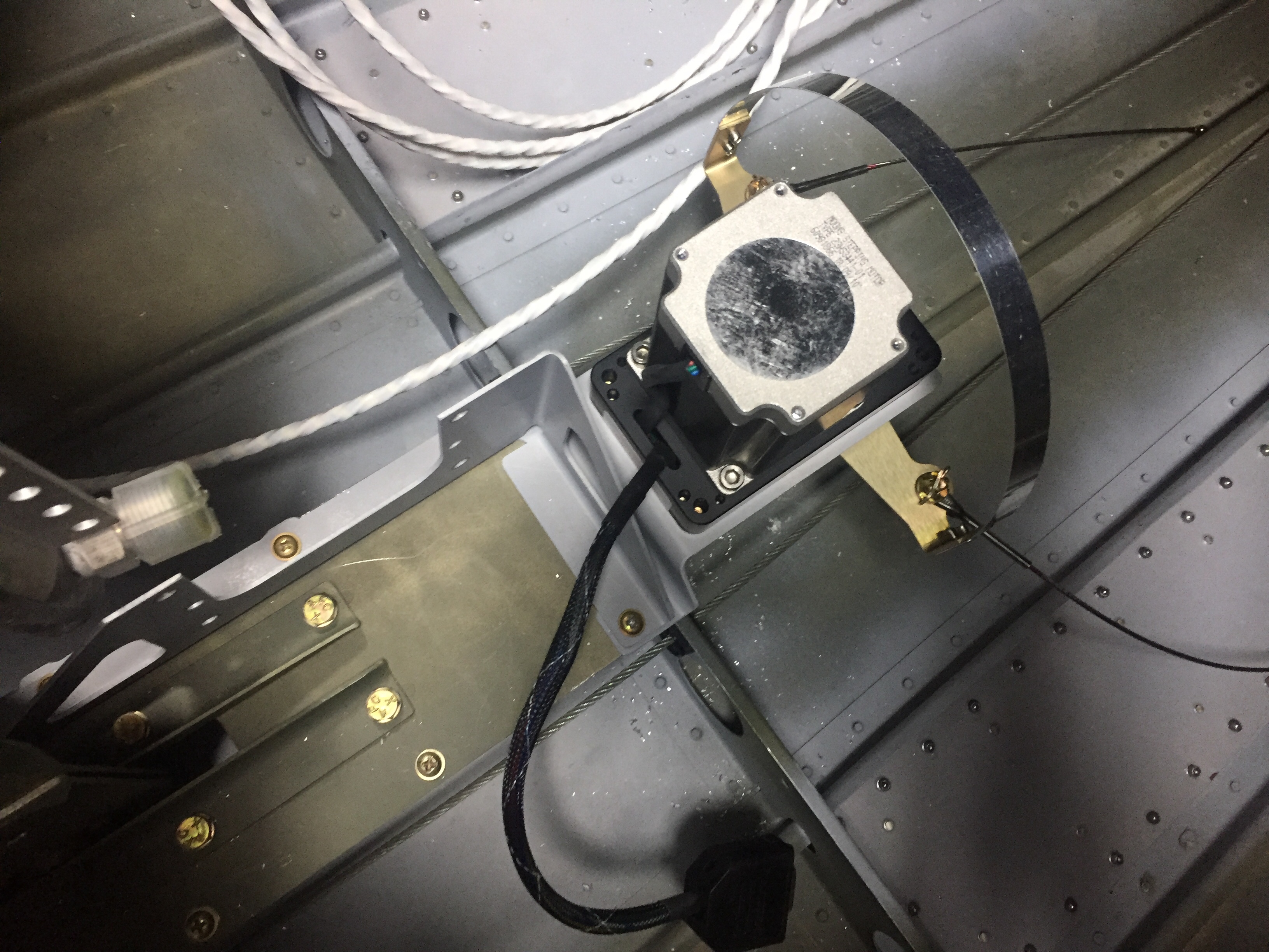
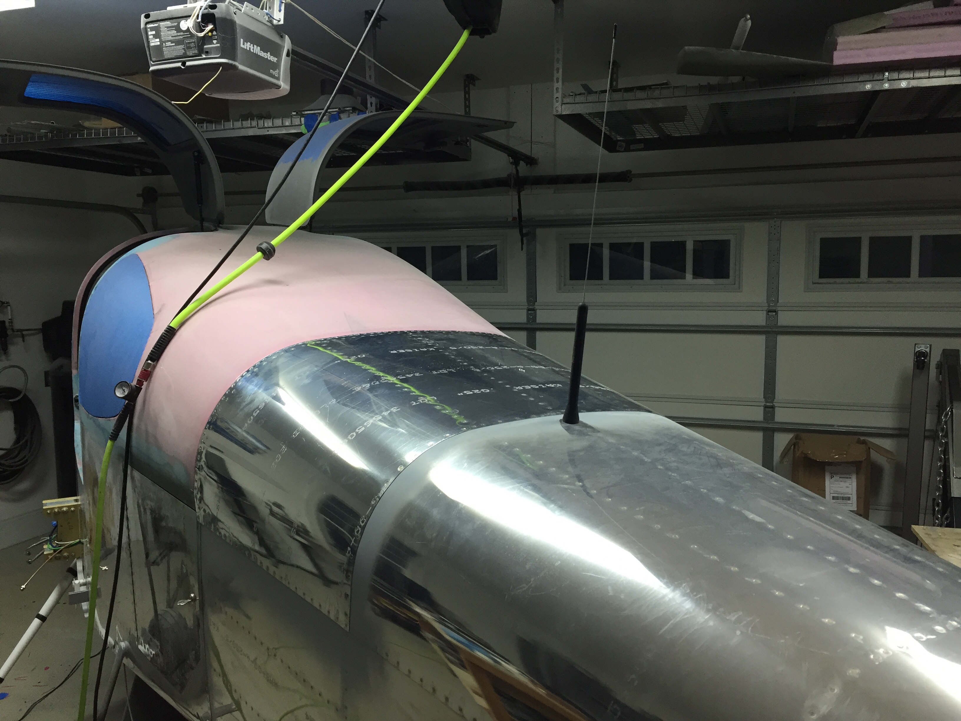
I quit trying to cheat the system and installed the ELT antenna on the top of the tail cone.  I tried every which way to hid that hideous monstrosity of an antenna but my conscious told me that it is probably the most important antenna on the airplane thus deserved its place per the install manual.  I’m sure it will grow on me.  The idea of burying it in the tail cone or tail fairing was tempting, but a talk with my DAR convinced me otherwise.

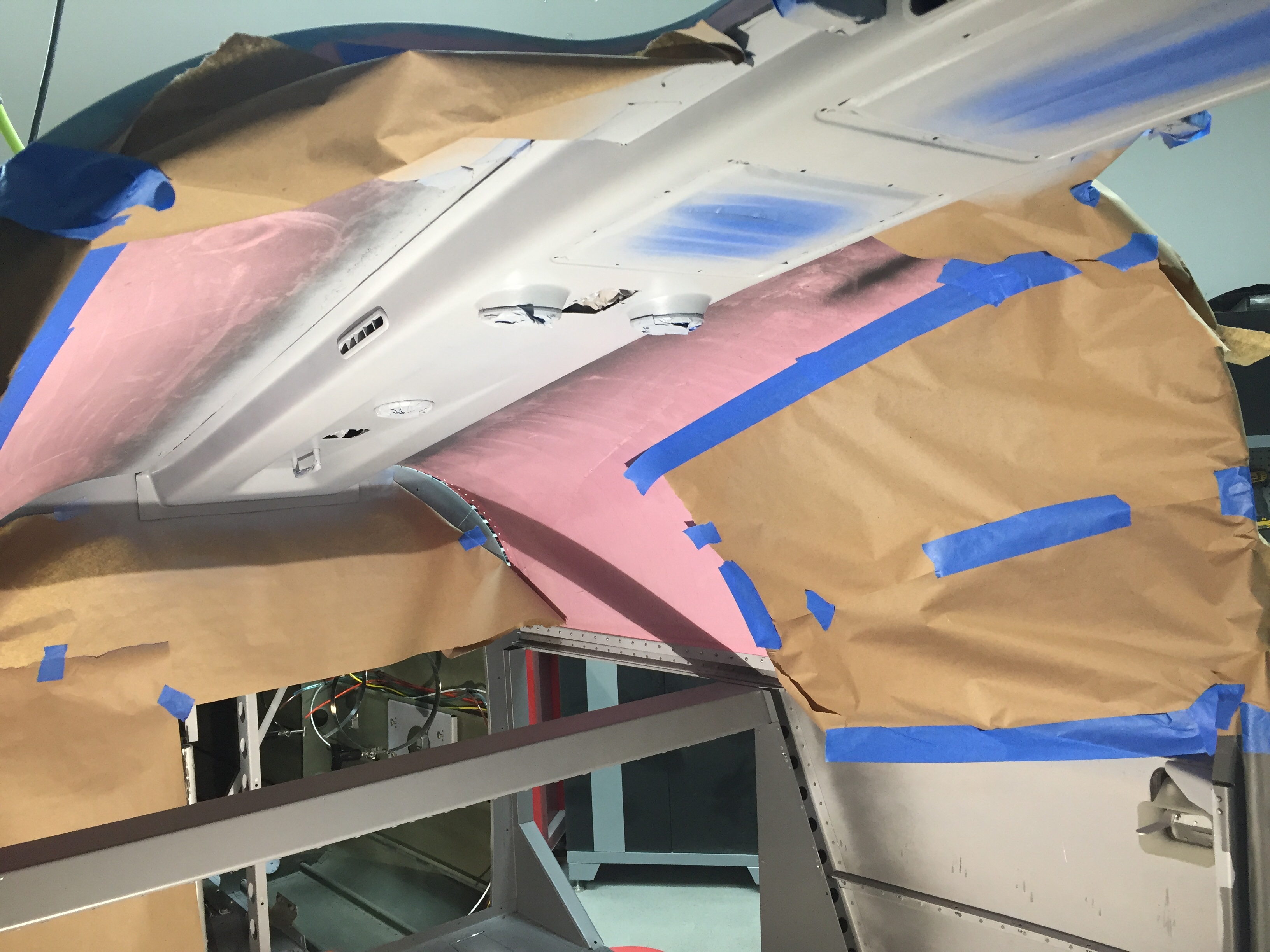
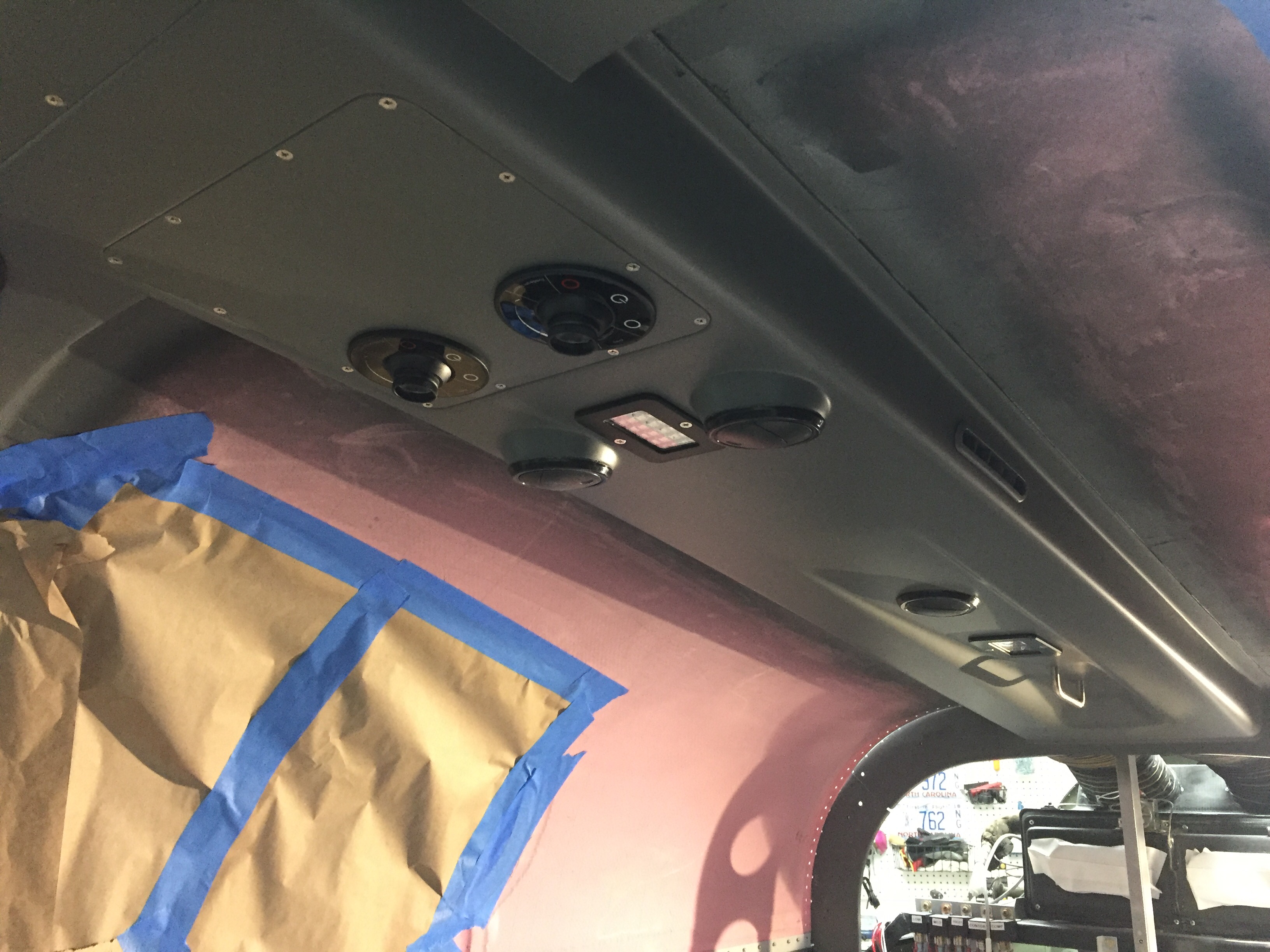
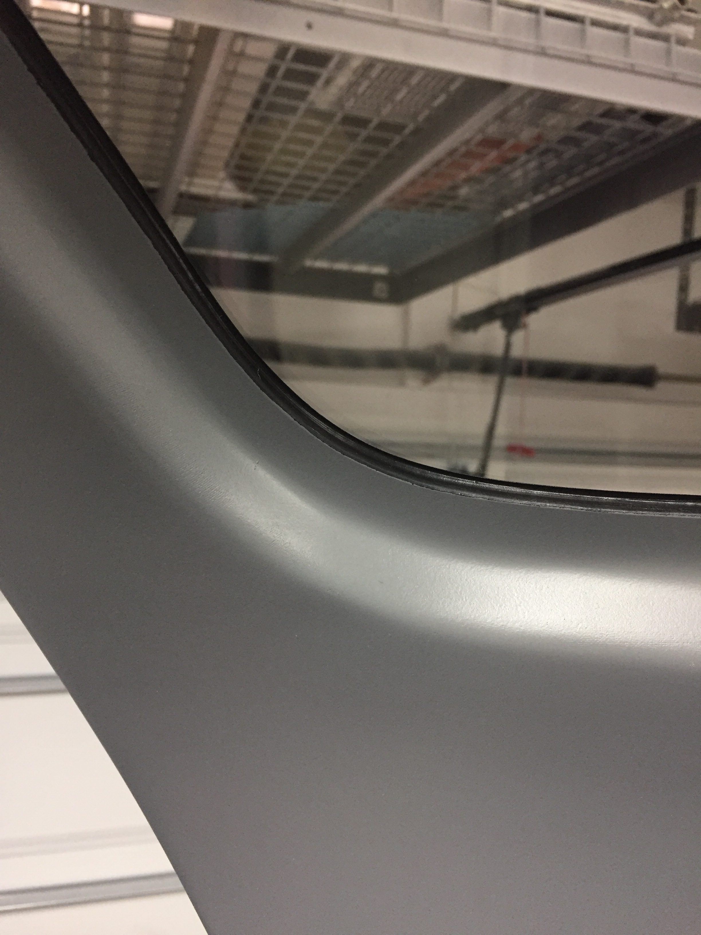
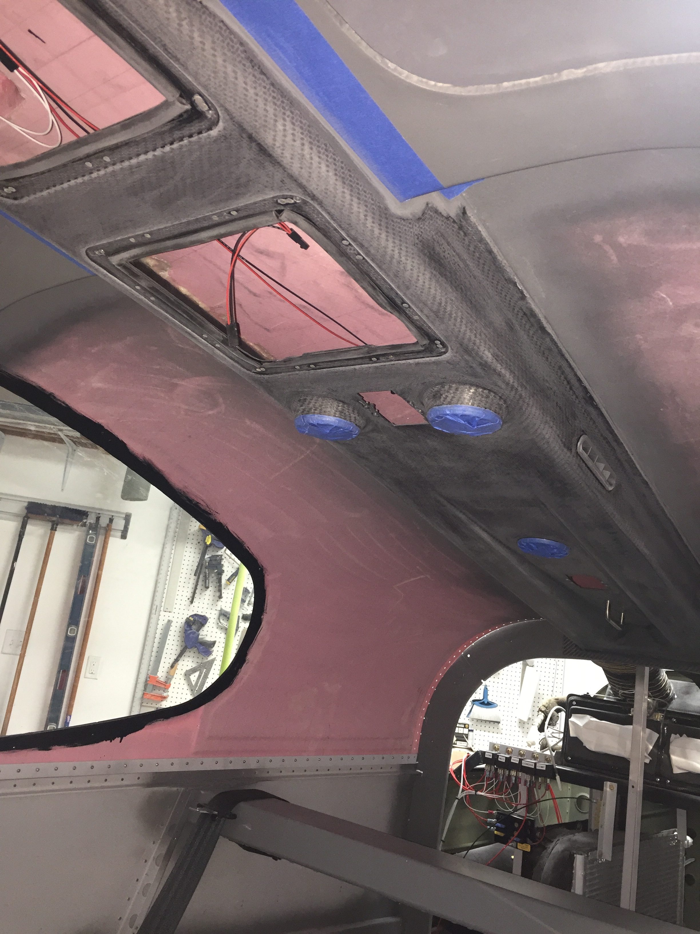
Continuing in the cabin, I spent an afternoon applying the headliner material to the fiberglass shells from Aerosport that had been trimmed for quite a while now.  It was a bit of a messy job with the spray adhesive, but not difficult at all.  I took my time and kept my fingers clean which resulted in a darn near perfect result.  After putting enough Velcro to hold a car upside down, the headliners slid into place and really dress up the cabin cover now.  The color matches great and was overall a lot easier than trying to smooth and paint the cabin top itself.

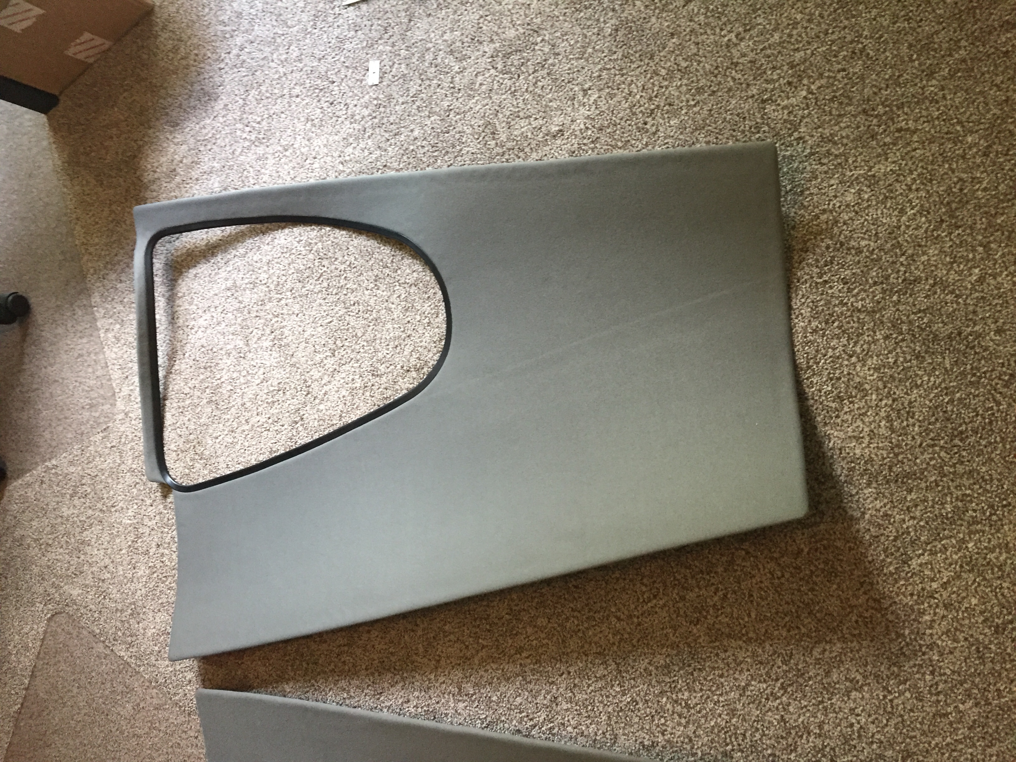
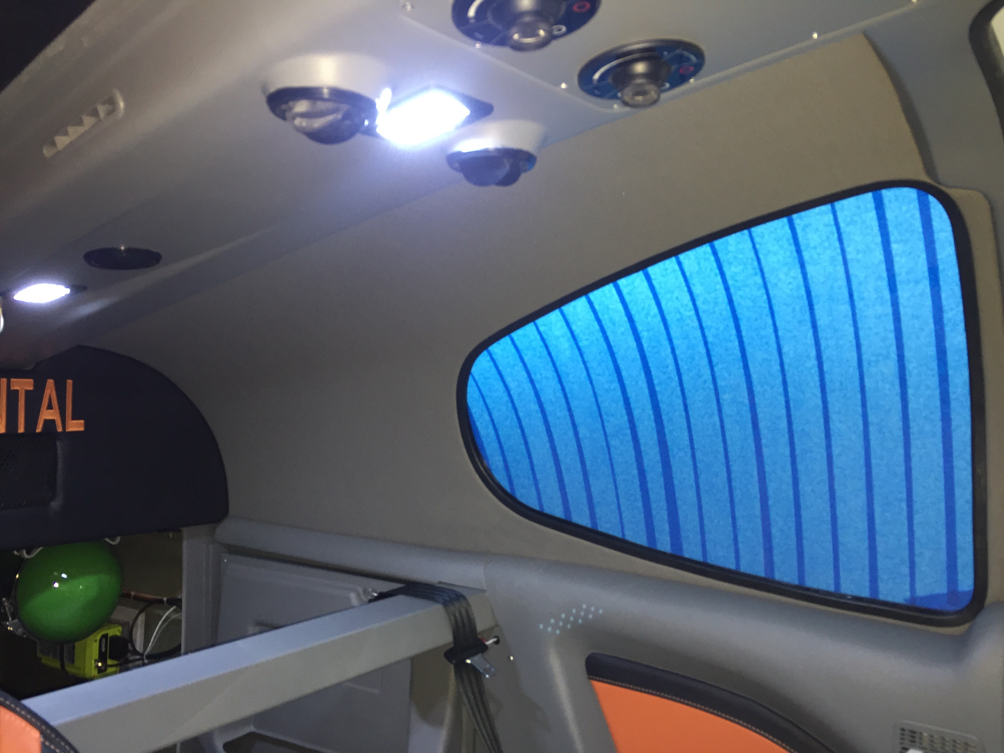
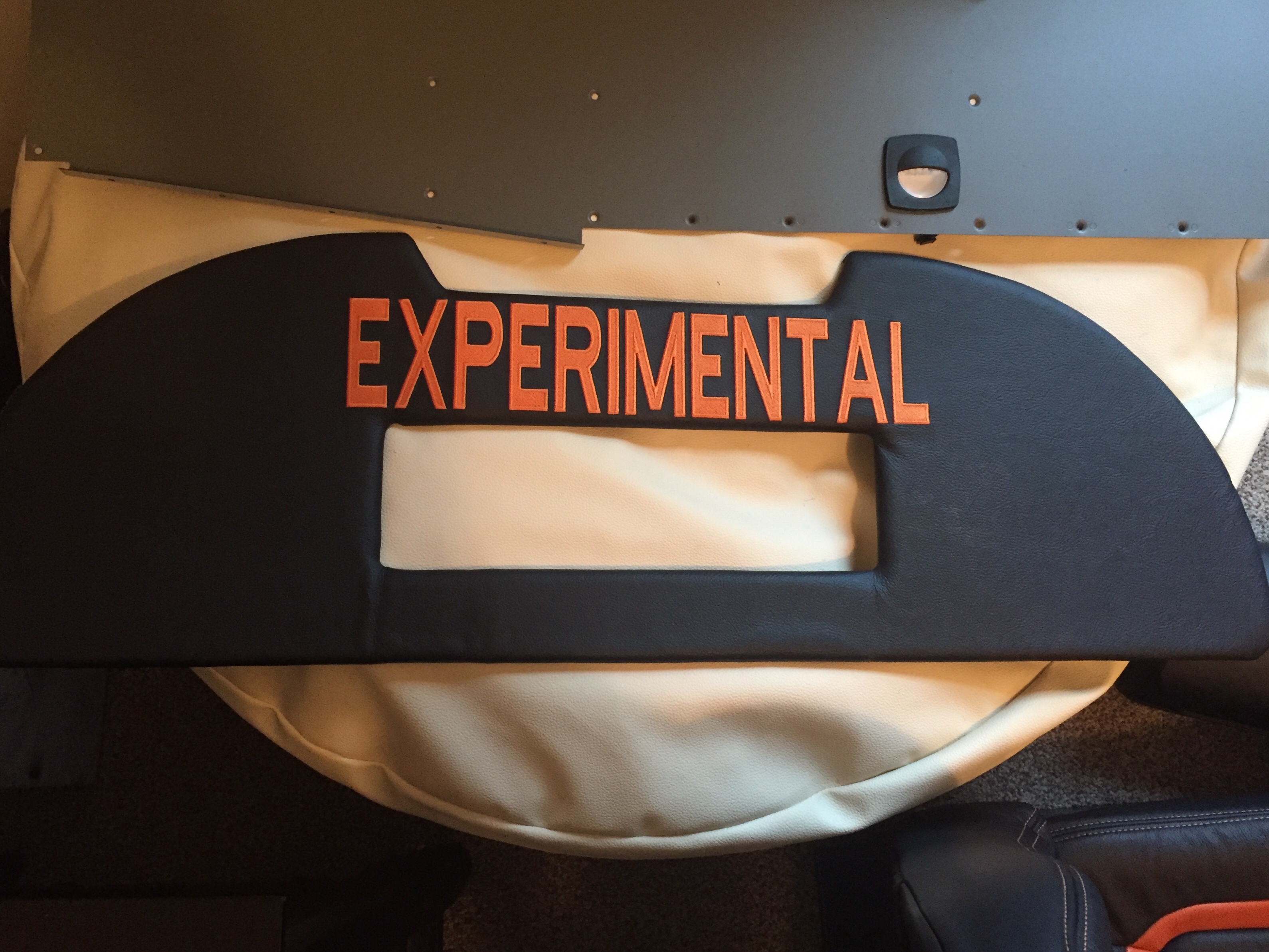
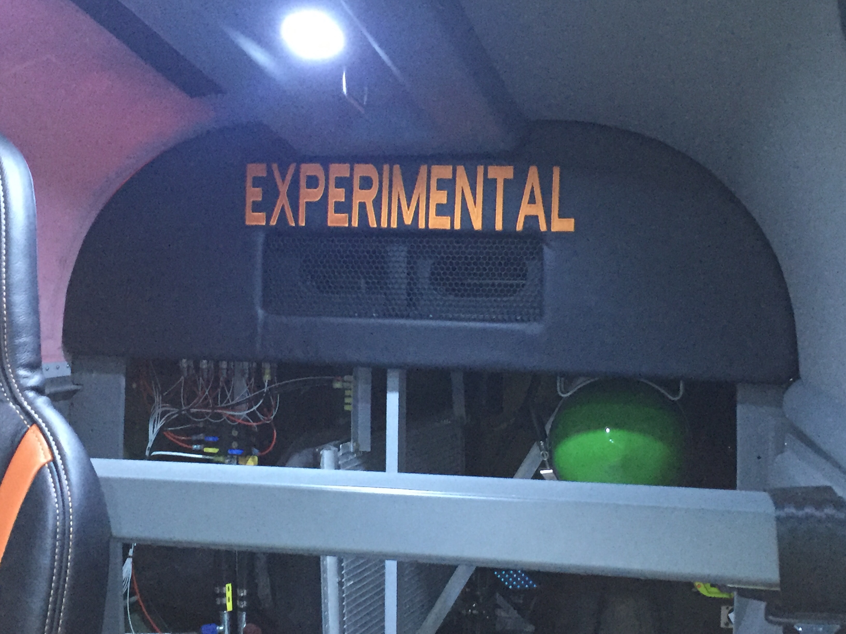
Finally, the rear bulkhead cover was back from Aerosport with the matching leather and embroidery.  I used Velcro to mount it to the bulkhead panel after installing a grill for the air conditioning return.  It turned out great and I’m really pleased with the fit and finish once it was all installed.  The cabin is really coming together with the rest of the rear side panels installed and inserts in place.  It’s tempting to put the carpet and seats in, but I’m holding off to keep them in good shape and clean while I finish building.

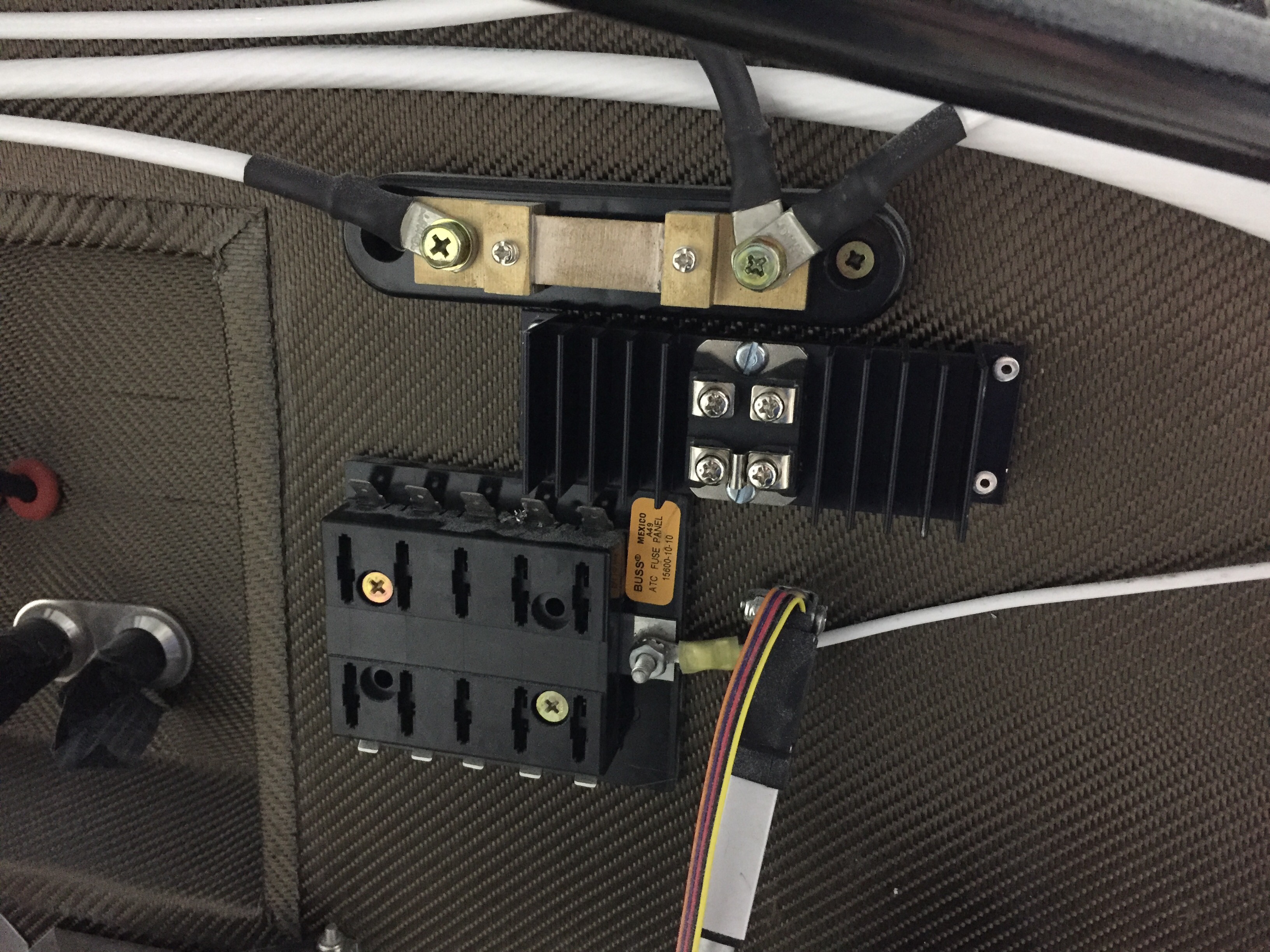
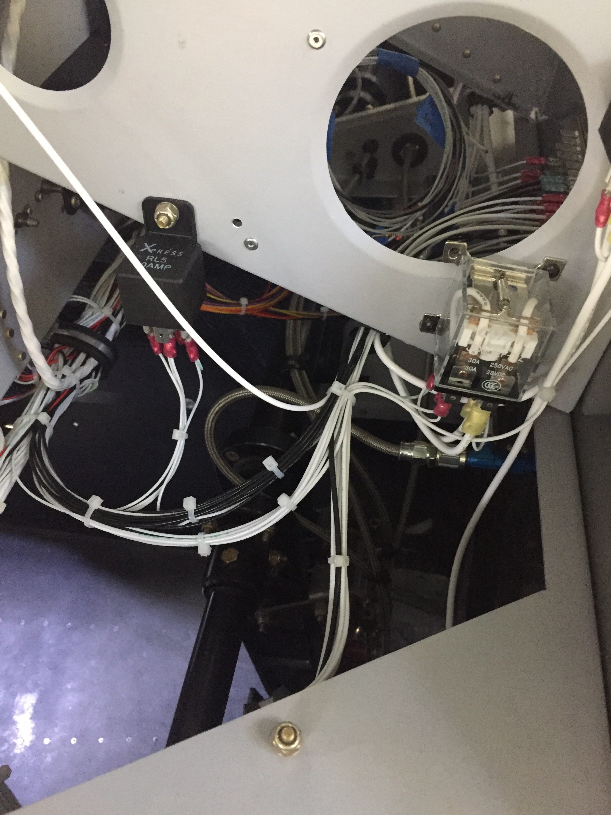
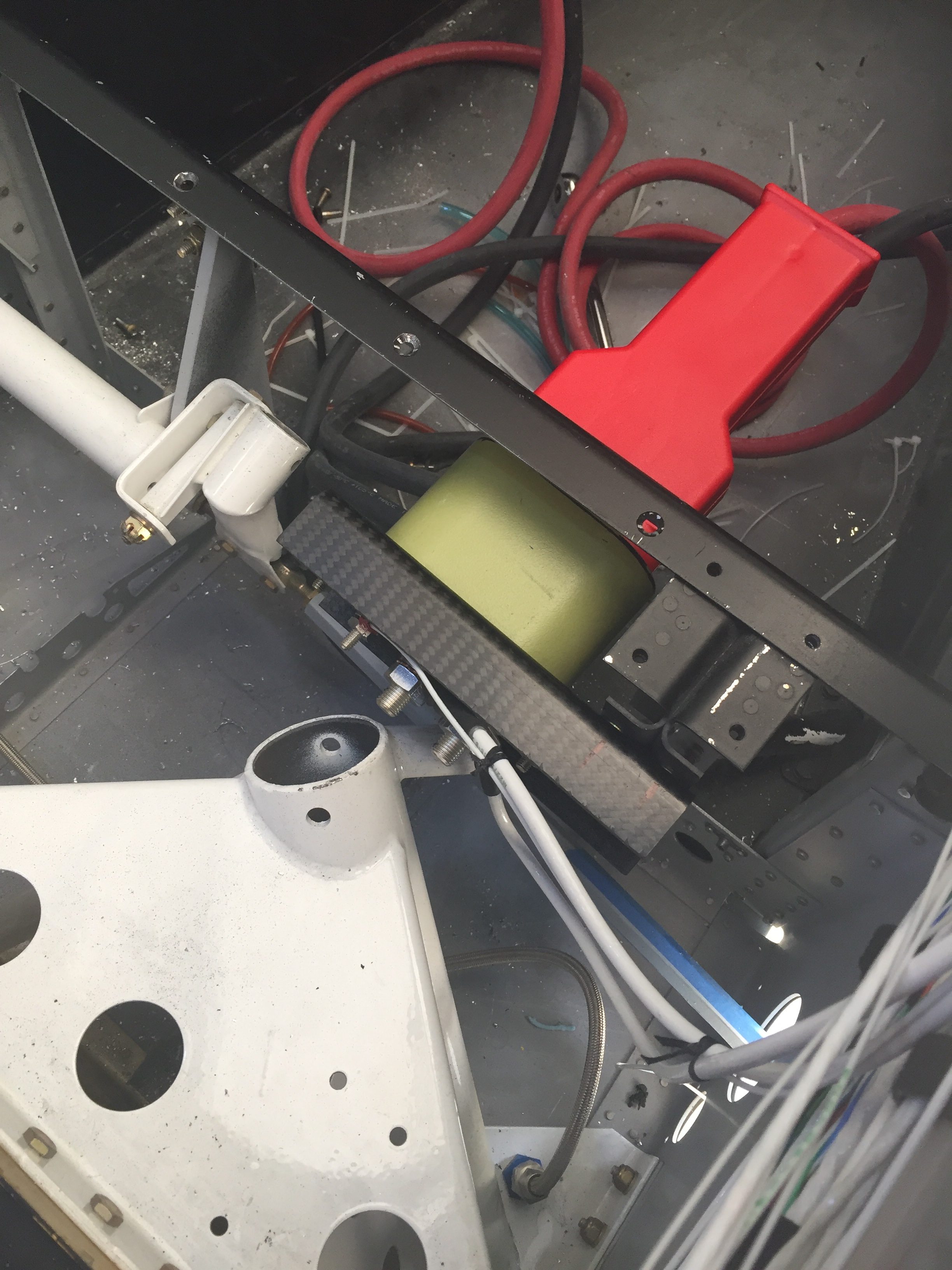
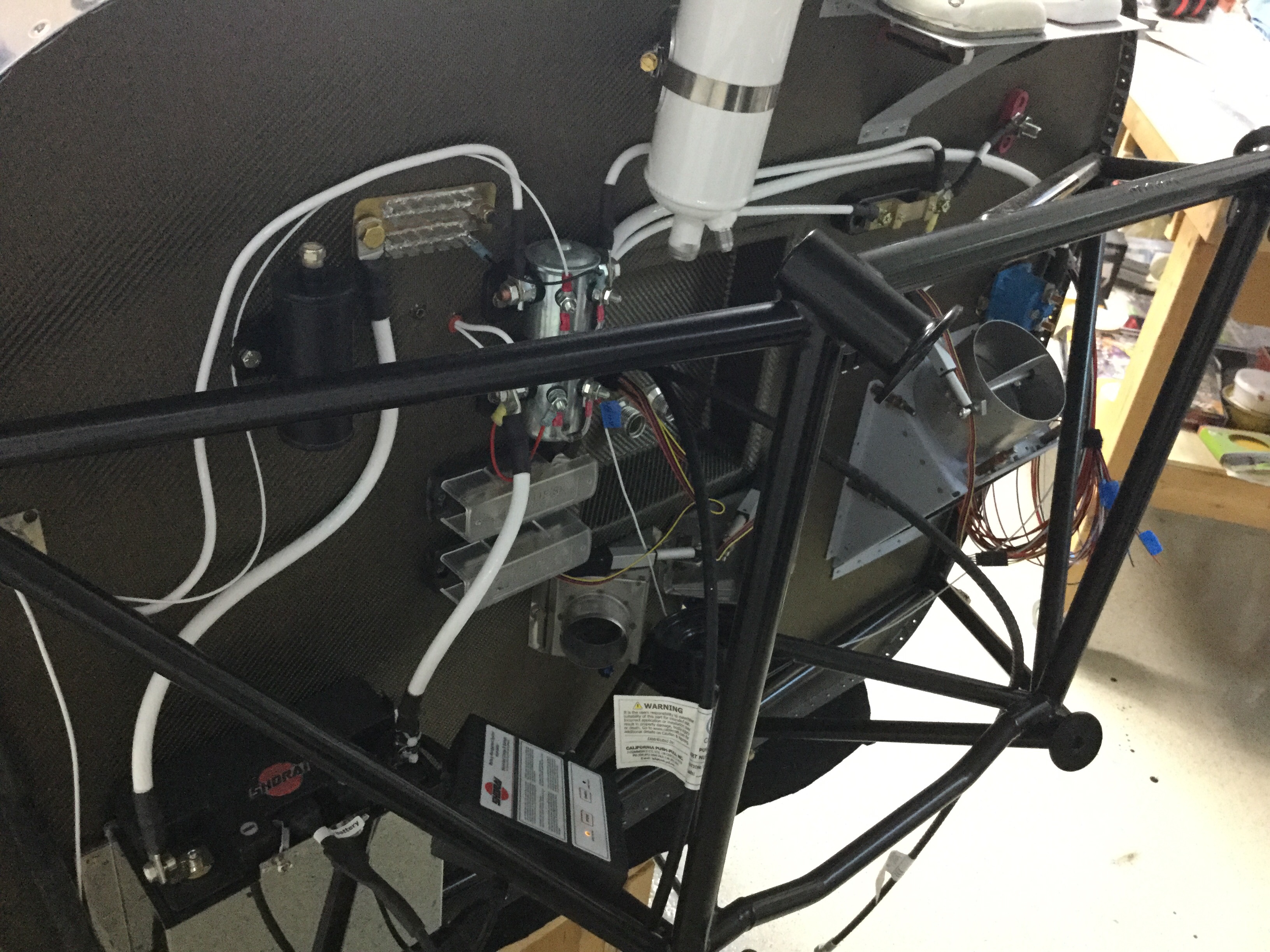
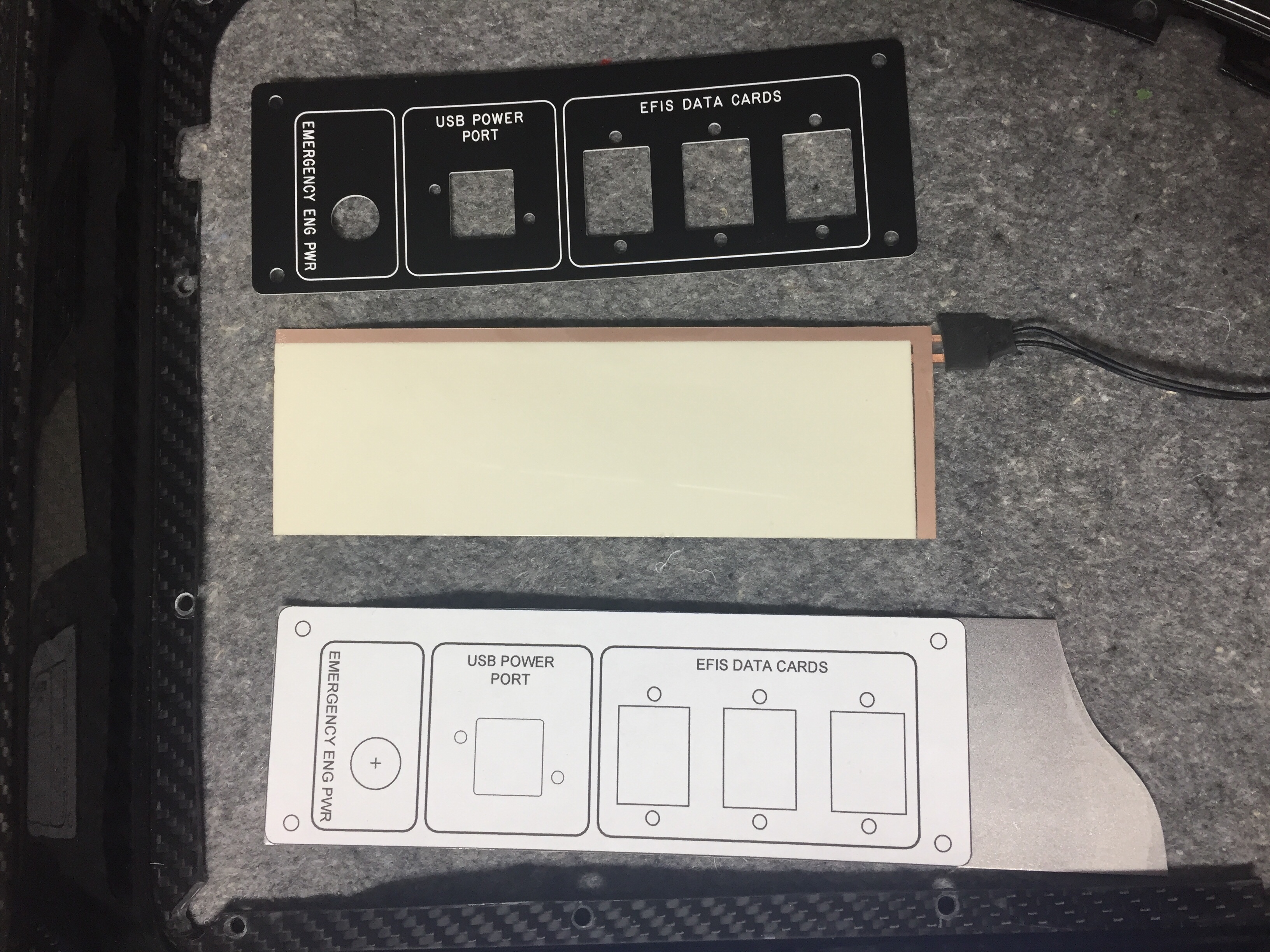
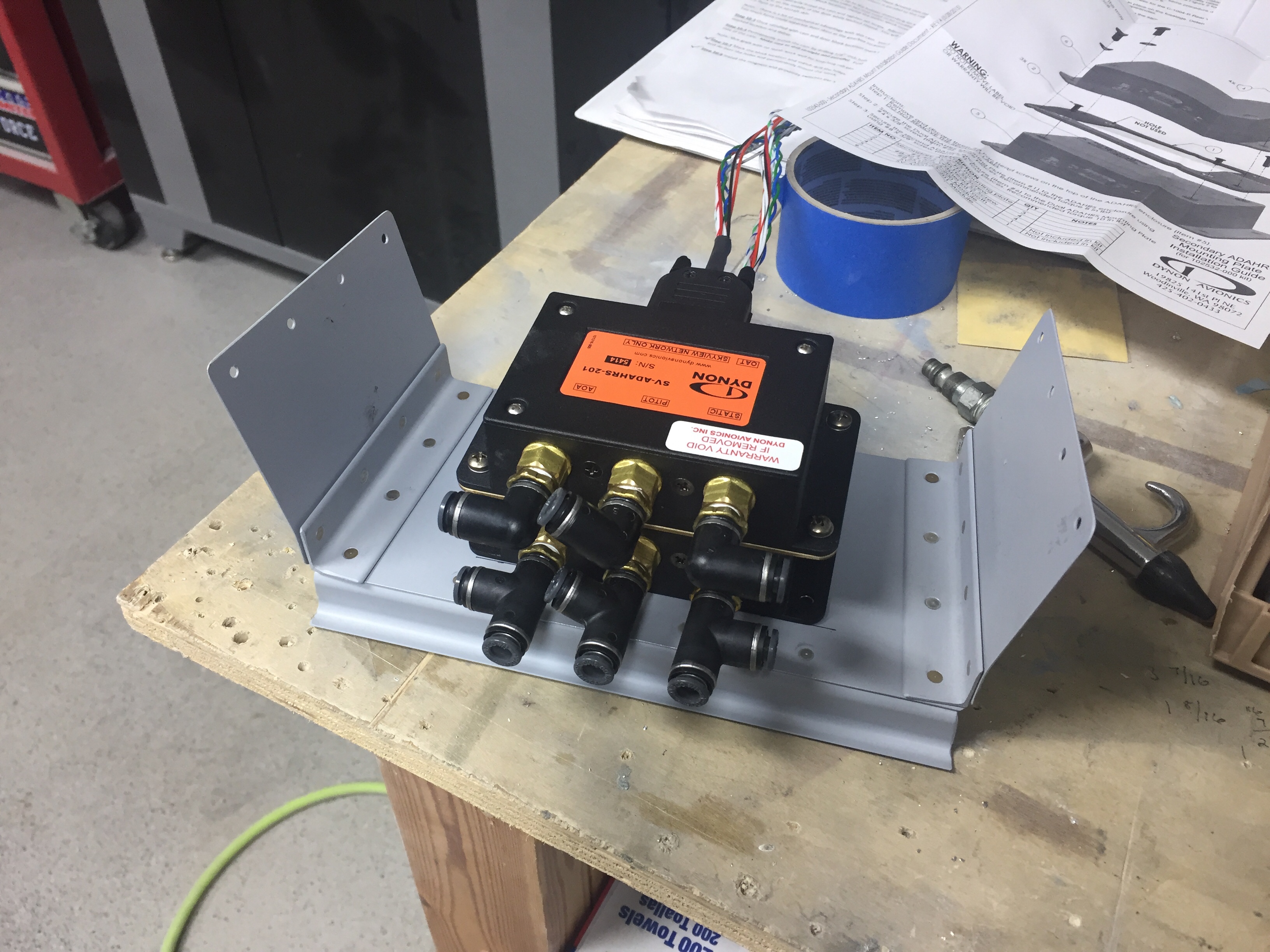
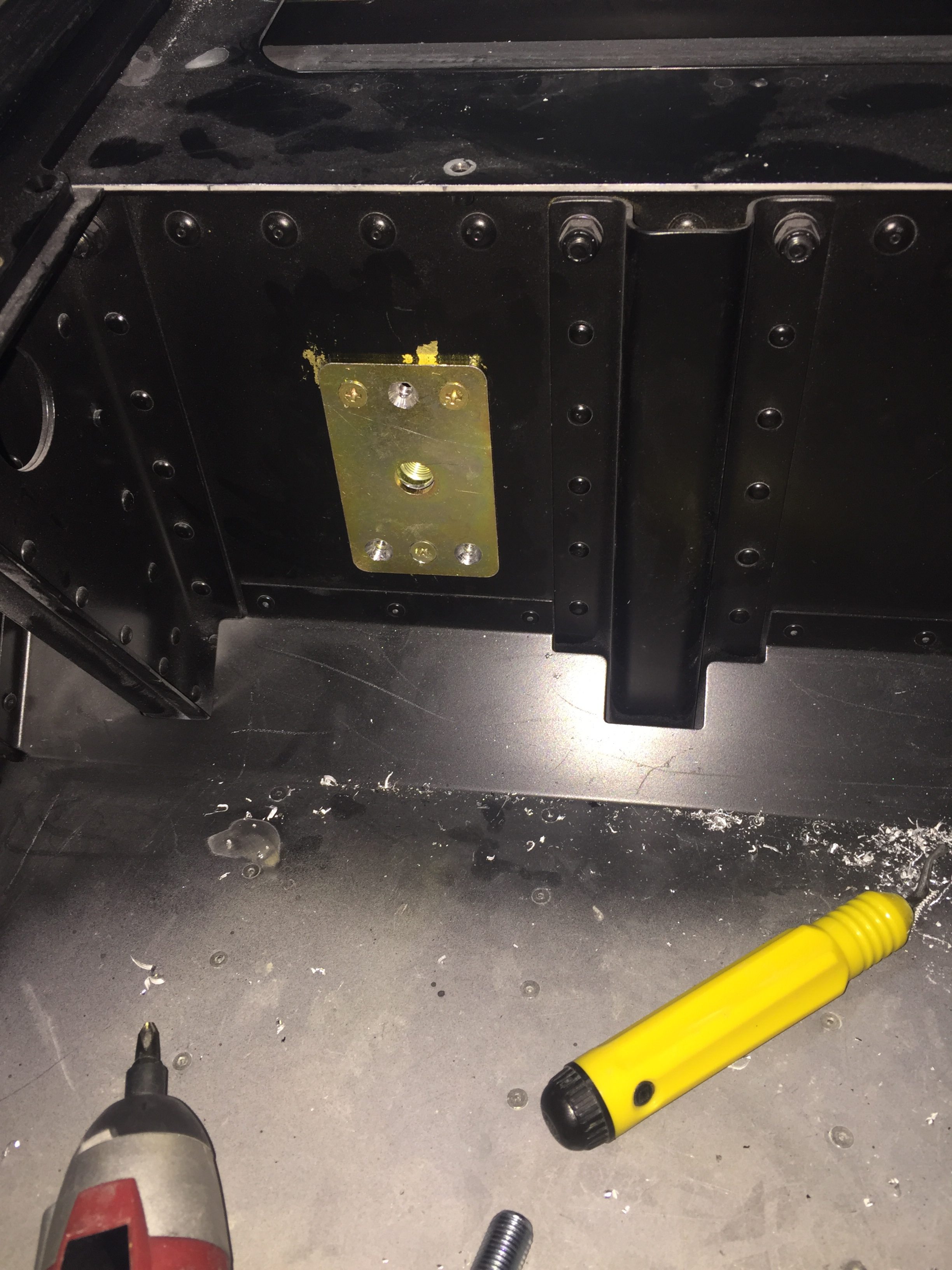
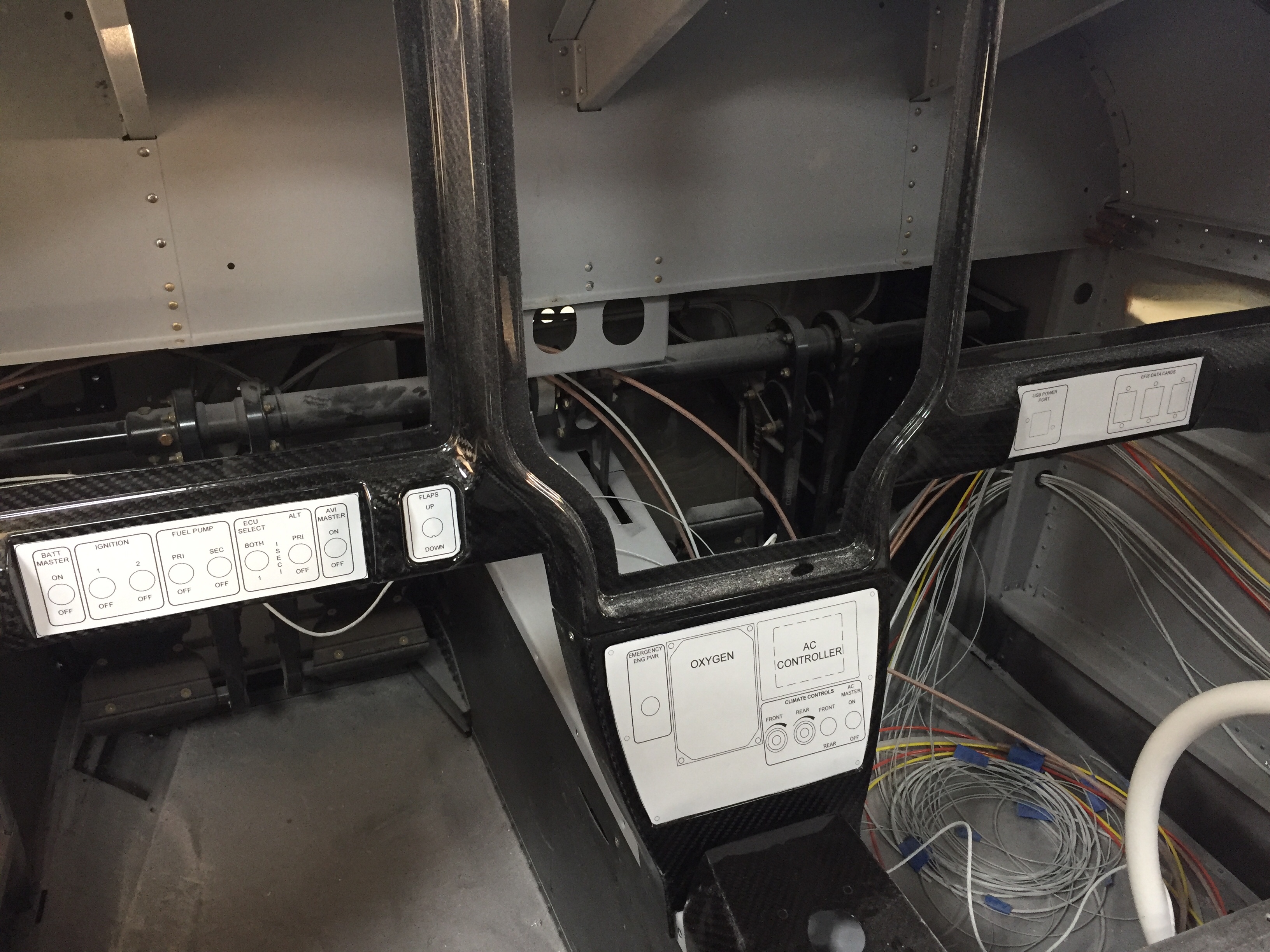
Upfront, I had an epiphany about my shotky diode and how it should be used to protect my engine bus.  The goal was to isolate the engine bus from the rest of the system such that I can turn the emergency power switch on (direct connection from battery to engine bus) and not have the electrons go to the man bus.  This essentially covers a short somewhere in the system or electrical fire behind the panel and gives me a bit of redundancy on keeping the electrically dependent engine going.  I wasn’t placing it on the proper power lead on the schematic, so it finally dawned on me it should go from the main power supply instead of the backup lead.  So, I installed it on the firewall and will work on a solid copper bar to hook everything up.

Smooth details

One of the last big fiberglass tasks is to layup the windshield fairing to the upper forward skin.  It’s a involved process with 10 layers of varying width glass strips followed up by a few coats of filler and epoxy to get it all nice and smooth.  I used cardboard to make a 7″ radius template and cut all of the fiberglass in preperation to layup the fairing.  I took other’s advice and died the epoxy black that will help create a nice finish from the inside with the Sika primer painted on the plexi.  This avoids unsightly views of the fiberglass from inside the cabin.  No pictures of the process as I had epoxy and fibers all over me, but it was a long afternoon with a lot of mixing.  I found that it was difficult to keep the layers precicely on top of each other and wound up with a few lumps and bumps along the way.  All were under the template radius, however, so could be fixed with filler.

The layup turned out pretty well and the next step is to apply filler.  I ordered a 2 mil vinyl plumping tape from Amazon Officially Approved Totally Legit Aircraft Supply Company and applied that over the electrical tape that marked the edge of the fairing.  This is probably the hardest aspect, as getting a nice smooth and even line is a bit challenging.  In the end, I did a lot of measuring and then eyeballing to get it good enough.  It probably isn’t perfect, but it looked good to my discerning eye.

My first coat of filler was the West epoxy mixed with micro to give some good ridgity over the layups.  I died it black just be be sure a good coverage again and made it good enough under the template.  After a quick sanding once dry, I used SuperFil to complete the curve which is much easier to apply and sand.  All in all, it took about five applications to get everything just the way I wanted it.  I used my favorite soft curved sanding block to sand and just judged by feel any high or low spots.  I’m happy with the turn out and I’m sure Jonathan will touch it up when he takes the plane for paint next year.

On the inside, I have one little streak of white from the tape which is a bit aggrivating, but nothing I can do about it now.  It may be covered by the side panel and glareshield, so not too worried about it, but it just annoys me.  The rest of the windscreen interior turned out absolutely perfect.  Again, the Sportsman method of taping and using Sika was a huge aspect of getting a clean finish.  It’s really cool to sit in the cabin now and look out through the windscreen!  It’s also nice having the cabing almost entirely closed in to keep it clean.

I am getting the last bits of interior from Aerosport and putting them in place as I go.  The panel inserts came with the seats and turned out great.  They are easy to install and really add a bit of class and color to the interior.  The baggage bulkhead looks great as well with the EXPERIMENTAL embroidered on the leather.  I’ll be putting a mesh grille in the cutout for the aircon return vent.

I finally got started on the wheel pants as well now the gear is on and it’s exciting pulling more parts down from storage.  I really want these pants to be finished well and have a nice fit, so I’m taking my time prepping the seams and mounting points.  I’m going to use SkyBoltz instead of traditional nutplates to allow quick removal and installation of the pants.  I don’t plan on having access doors for the valve stems because I just don’t want to do the fabrication neccessary.  This way it forces me to have a good look at the tire and brake while checking pressures monthly.  FYI the SkyBoltz are far cheaper direct than from ACS.

One issue I had to pause on and get some help was the wheel pant spacer that bolts onto the wheel nut for the main gear.  On initial fit, it’s proving to be way too long and I was hesitant to cut it allowing the rear portion of the pant to fit.  Beringer says trim away, however, so I think it’ll actually save me a few steps later in the process since I’ll be able to trim at a precise angle to match the pant and avoid using flox to build up a flange on the inside of the pant.

Meanwhile, I fabricated the last of the stainless steel brake lines and installed them to the calipers.  I am now considering swapping the calipers from side to side which will put the bleeder nipple on the bottom.  I’ve always had the nipple on the top of the calipers, but using a pressure bottle to bleed the brakes from the calipers up will allow the air to be pushed up naturally instead of forcing it down and the nipples should be the lowest point in the system for this.  If the lines can still be used, I’ll swap them.

Next up is some exciting stuff as we jet off for vacation and engine build school in Kamloops, BC.  Stay tuned for details!

More wiring plus some more wiring then more wiring

Wiring continues as I think I’m nearing the end only to discover more runs that need to be installed.  I reworked the nutplates for the back up battery on the subpanel and have the subpanel back on the fuselage temporarily to continue bundling wire runs.  The amount of wire I hadn’t thought of is a little higher than I was expecting, as I thought I had a good handle on the “pre-work” for the avionics.  Rudder trim board, a few relays, the lighting control module, and a few others all popped up as I put components in place.  I’m working hard to keep the runs neat and tidy as I go.  I’ll ziptie everything in place once I feel that I’m done with wiring but I’m sure I’ll forget one or two and need to redo the zipties.

I had to have one of my panel overlays re-etched since I decided to add an emergency power switch for the engine bus.  I had originally designed a two relay system that would automatically provide backup power directly from the battery to the engine fuse block (bus) should the main power supply fail (master contactor, etc.).  A three position switch would be off, armed, and test allowing the system to be tested before flight.  I decided it was too complicated and didn’t design the panel or schematic for it, but now regret that.  Essentially, it is only redundant for the master contactor, but now that I’m visually seeing the path of power all going through the contactor as a single point of failure, I want a backup.  So I’m running a DPDT 40 amp relay from the battery to the engine buss.  I had considered a diode which would isolate a short in the main system but decided to not plan for multiple modes of failure.  The switch will be red guarded and the second pole will have be an input for EFIS annunciation to verify the relay’s activation.

I also forgot about the control stick wiring, which is the last connector needed for the ACM to be fully plugged in.  I don’t want to fit my control sticks until I rig the surfaces, as the throw of the stick as is now is greater than when properly rigged.  So I pulled wires, labeled them, and terminated them on the ACM side.  This is when I realized I went a bit overboard on the number of switches on the sticks.  I had planned on the typical Coolie hat trim switch, PTT, AP disconnect along with a TOGA, rudder trim toggle (horizontal orientation), and possibly a IDENT or comm swap.  It’s a lot, I know.  The Tosten grips have all that but I found out that I can’t use all of them!  The AFS/IFD setup doesn’t have an input for a TOGA as discovered after a lot of research and question asking.  The AP simply auto sequences the MAP based on the flight plan so no need for a TOGA.  The downside is not being able to go missed earlier than the MAP while on AP, something I’m used to in the Diamond with the G1000.  Not the end of the world.  I decided against a IDENT and comm swap switch as I just think they are not needed since I have to touch the panel anyway and I mean seriously, am I that lazy??  Ha, yes I am, but those two features still didn’t make the cut.  So, I wound up with three axis trim, PTT, and AP disconnect (AFS calls this CWS which it’s not but whatever).  A TOGA is reserved as a coming feature from AFS.

The GPU receptacle is also wired up now in its hidden location under the copilot’s seat.  I wired the GPU contactor such that it will power the full system but not charge the battery, as the Shorai will have it’s own balanced lead to connect the dedicated charger on the ground if needed.  Because I’m electron dependent, I will never jump a dead battery and take off, so no need for external access.  The GPU will be in the hangar for maintenance and/or learning the avionics.  I cut a little flap in the seat foot well wall and mounted the receptacle to the seat rail support.  It worked great and will have one bolt on the seat bottom to help secure once that area is all complete.

The big wires were taking up a lot of room on the shelf and with the components on the firewall all mounted, I could get the thick stuff installed.  I took some time to determine what size lug would be needed at each end of wire and ordered all the supplies in.  Great move because I had all I needed plus a few spares of everything.  The crimper I bought from Amazon worked well and it was a pretty easy, fun job overall.  It helps me visualize the power system now even better and I’m happy to say that I feel safe and secure with the architecture providing power for the plane.

After receiving the newly etched panel, I could fabricate the last of the switch panels so the avionics would be ready for final install.  Just like all the others, I started with a printed 1:1 image of the panel I had designed spray glued onto the aluminum sheet.  I cut that out then final trimmed it using the acrylic overlay before painting it black.  The back light panel is placed on the aluminum panel and positioned using the overlay to get it just right before trimming for the switch and USB ports.  This one was pretty easy with large cut outs.  I use 3M double sided tape to secure the back light panel then lay the adhesive backed overlay on top to finish it all out.  I use a Sharpie to color the white on the edges of the overlay to help control bleeding from the back light and give it a nice finished look.  I did have a little trouble with the wires on this panel and wound up replacing it all together with 22 AWG Tefzel soldered on the panel itself.  I wish I had done that with all the others, as the wire used from the panel is crappy and hard to terminate using the micro-molex connectors.  It turned out great, though, and is the last piece of the instrument panel.

Finally, I worked up two brackets for the micro switches on the doors and wired those along with the one on the baggage door for the lighting control module.  I also used the micro switch on the baggage door as the safety switch input for the EFIS annunciation.  More wires to run, oh boy.  A pretty quick job that should work just fine.  I did have to run an additional wire up to the overhead as I had picked up power and ground for the door lights from the overhead lights and that’s not how the lighting control module is set up.

While my plane does have a lot of wiring, it’s nothing compared to the big boys at work.  This shot is behind the port side avionics bay in the C-17.  Now that is a lot of wires!

Back that light up

One of my most exciting side projects on the plane is to have a truly unique instrument panel.  From the start, I have wanted a back light system similar to fancier aircraft out there and to pretty much every car out there.  Glareshield lighting, post lights, or dome lights just don’t work or look the same, so I wanted something better.  Ed Krantz did a great job using LED strip lighting but had to do a lot of work to get it working.

As briefly discussed in THE ART OF DESIGN, I decided to experiment with electroluminecent panels.  These EL panels are almost paper thin, flexible, and can be cut in all sorts of shapes.  Better yet, they are dimmable and have a uniform light output.  After a successful prototype on the overhead console panel, I pulled the trigger and ordered the full layout of the EL panels and the laser engraved acrylic overlays.

The EL panels came from Marc at Lightkraft via Etsy.  Marc was phenomenal to work with and took a personal interest in the project.  We had to iron out some dirty details on orientation, power leads, size constraints, etc.  I wound up taking his limfacs and finessing the panel layout a bit around the EL panels to make sure everything lit up as desired.  I also had to be strategic on where the power leads would be located along with the two edges that are unlit where the leads run.  On those two sides, it’s about 3/16″ that is unlit and cannot be cut, so positioning those correctly was key.  The other two edges could be cut and shaped in any way needed.  Finally, holes in pretty much any shape can be cut out of the middle to allow for switches or components without affecting the rest of the EL panel.  On any cut edge, the panel must be sealed to prevent oxygen from ruining the EL material.  Marc suggested clear acrylic nail polish which was easy and quick.  The prototype was done in white, but I wanted the final product in all blue.  Marc did a great job taking the 1:1 sized PDF I produced from my CAD design and producing the panels.  He provided a transformer based on the total surface area of the panels so all will be wired together and be on one dimmer.

Since AFS helped design and is producing a quick panel for me, the metal inserts for the four major sections of the Aerosport 310 panel are being cut and silk screened by AFS.  I wanted that as a back up to the EL panels just in case those didn’t work out or fail and are not replaceable sometime down the road.  After finalizing the design with Stephan at AFS, I sent the same CAD design to Matthew at Aircraft Engravers and requested all the panels be cut from black on white acrylic, just the same as the overhead console test panel.  Matthew was able to cut all component, switch, and screw holes then laser engrave all of the markings.  The acrylic panels have a self sticking backing so applying them for good is as simple as pulling off the backing and sticking them on the metal panel!

I took some time to ensure each EL panel fit the area needing back light and trimmed a few spots to clean it up.  I used a 5/8″ punch to punch holes for switches and dimmers in the EL panels.  The idea was to avoid the EL panel contacting any metal avoiding shorting and any interference noise the panels may translate to the air frame.  From what I can tell, neither is necessary as metal doesn’t seem to bother the EL panel and test flying the prototype in the Diamond yielded quiet radios and headsets.  After all of the holes were cut and trimming was completed, I turned into a little kid and played with everything in the dark to make sure all engraving was properly lit.

Next task is to cut a relieve for the power leads to rest in.  Since the wire is soldered onto the EL panel, it needs to slip either to the edge or behind the metal panel so that it is all flat once completed.  The areas where EL panels are not near and edge, I cut a slot for the leads to fit through ensuring no exposed lead touches the aluminum.  Several locations will require the leads coming out from the side of the acrylic panel and going into the carbon fiber structure through a slot.  Those are a bit tough to cut out but with patience and a lot of though prior to cutting, it works just fine.  The main switch panel and flap switch panel were the toughest ones.

To install it permanently, I cleaned the metal backing panel and positioned the EL panel with 3M clear double sided tape (the same stuff Van’s recommends for trailing edges).  This is really just to hold it while placing the acrylic overlay on top.  The backing is removed from a small section of the acrylic overlay so that I have some adjustment playing the overlay on the metal panel.  Once everything is lined up just right, I removed the rest of the backing and pressed the acrlyic down evenly.

The end result is a sandwich with the acrylic on top, EL panel, then metal panel at the back.  There is just a slight thickness difference over the EL panel, but not enough to be noticeable without really inspecting up close.  If you’re doing that, keep your judgments to yourself!  Switches and dimmers are installed just like you would anything else and before you know it, I was able to screw the panel on the overhead console and fire it up.  I went ahead and wired all of the switches and had the dimmer pots ready to go, so the overhead console and panel is now complete pending black screws coming from AFS!

Overall, I am really impressed with the result and happy I did the project.  It wasn’t cheap, costing about $1000 with most of that coming from the engraved acrylic overlays.  The EL panels were about $200 after all said and done.  The acrylic would have been much cheaper if I had only done the areas around each switch or back light panel, but I wanted a uniform look across the cockpit.  I would absolutely recommend it to anyone wanting a little extra light and wow factor on their build.  The CAD work was fairly simple and fun as was putting it all together.  I can’t wait to get the rest of the avionics and get the whole thing fired up.  She is going to look stunning in the dark!

Shutting the door on the doors!

Doing things better the second time seems to be a driving motto for my project.  The paint on the overhead console is a great example.  With it properly prepped, I sprayed primer on it using the adhesion promoter and instantly saw improvement.  Once the primer cured, I did some test scrapes and the stuff stuck like epoxy!  After that, the color was easy, again using adhesion promoter after a good wipe down with tac free.  I followed all of that up with two coats of the satin clear on the entire painted interior.  It’s about time I replace the cartridges on my respirator.

I also fixed the rear foot well spar paint after cleaning the old stuff off and re-scuffing and priming the surface.  I wound up test fitting a few pieces of the carpet just to get an idea of how much metal is exposed and what actually needs to be painted.  The Aerosport carpet is nice, I couldn’t have done a better job myself, but they aren’t an exact fit which is a bit irritating especially for how much it costs.  Not sure if all of the patterns are like that, but the floor carpet for the rear foot well is about 1/2″ too big on length and width, so one side or both will need to curl up a bit.  Never noticeable once it’s flying, just being picky I guess.

The doors are finally done!!!!  The last coat of color and clear went on smoothly and I’m calling them fully baked.  What a royal pain in the ass they were.  I am very happy with how they turned out, though.  I put the Aerosport handle covers on and got the Plane Around center cam final installed with the roll pin.  The door lights went in for good as well. I took my time putting the final door seal on from McMaster Carr and made the seam hidden by the strut and strut bracket.  I used a bit of E6000 glue to ensure no gap in the seal lets water in up there.  Holding my breath, I closed the door and much to my surprise, both closed with the seal on smoothly!  The right side door is a bit more firm on the handle motion, but the wife is happy with it which is all that matters.

Now that the paint is all complete on the inside, I was ready to install the front windows.  Repeating the process from the rears, the right window went in very smoothly and thanks to good prep work and patience, the inside finish is nearly perfect.  I wound up with a very nice fillet of adhesive creating a nice finish around the perimeter of the door cutout transitioning to the window.  I did notice that the strut now feels much better with the extra weight and doesn’t cause the door to fly open violently.  If anything, it needs a bit of encouragement to go all the way up but has no problem keeping the door open once it’s there.

It took one more evening of work to get the left window in which again went very smoothly.  One additional piece of prep was to put masking tape on the outside of both front windows to help clean excess adhesive from the gap.  It will just make paint prep a bit easier and quicker.  Again, that gap gets filled in with more adhesive after paint for a flush clean look and finish.

I’m back to cleaning up the inside, yet again, of dust and debris since the windows are now in and I can control what goes into the cabin.  The seat belts and receptacles were bolted back in and I riveted on the baggage door panel and gas strut (which I keep forgetting is on when the damn door hits me in the stomach).  Avionics are shipping soon so I need to get the wing root wiring harness complete to be ready to put the expensive boxes in next.

In Over(my)head

Just when I thought I was nearing the work on the inside, all hell breaks loose.  As I had put masking tape on the overhead console to protect the paint from scratches caused by fitting the headliner base, I wound up setting myself pretty far back by ripping off chunks of paint with the tape.  Now we all know it’s probably not the paint’s fault.  It’s mine.  Why do I do stupid things like not properly prep the surface and not prime?  Seriously.  WTF Tim?  Get your crap together.

Bottom line, I knew as soon as I painted the overhead it was fragile.  The paint had already chipped off a few spots around the metal insert panels and I was concerned that it wouldn’t hold up to normal wear and tear.  I chewed on having a professional painter take it and strip the entire interior but then decided against it, not wanting to give up control.  On the surfaces where I properly prepped and applied the paint, I was very happy with it.  I like the idea of being able to do spot touch ups with a spray can down the road.  All of the interior matches.  All those plus the thought of someone inadvertently sanding through filler while trying to remove the current paint helped me climb in with a razor blade, pile of sand paper, and a neck brace to start working overhead.

After about three hours of work, all the paint was off the overhead and everything had been sanded down with 120 grit.  Even though Aerosport says 320, I found that it wasn’t really marking the surface much, and I want the paint to stick this time!  I took my time around the vents and areas of the cabin top where I knew the paint/primer was strong such as the door frames and switch panel.  As I was removing the paint, I could obviously tell where areas were better than others.  Around the door frames that had been scuffed and near the switch console where I had primed, the paint was a real bear to remove.  That gives me hope I can do it right.

This time, I’ll use tack-free to wipe down the entire surface very well and remove any contaminants (something I didn’t really do before) then use an adhesion promoter while putting the primer on.  I have the fuselage all cleaned out from dust (again) and need to finish the touch ups on the door at the same time.  I’ll also spray the baggage door panel.  I’m not going to jinx myself and say that will finish the interior this time.

Meanwhile, my first two very expensive boxes of avionics have arrived!  The lesser of the two from Tosten had my two stick grips in it which led to lots of button pushing, trigger pulling, couch flying while making airplane, gun, and missile noises!  I’ll try to get a video sometime.

The big box was from Advanced Flight Systems as a prelude to the full panel being shipped in a week or two.

They were nice enough to ship me some advance components and harnesses such as the ADAHRS, servos, and EMS among a few other things.  I first ran the autopilot servo wire harnesses and already appreciate the value of having AFS wire the majority of the avionics.  I pulled 21 wires in about 10 minutes that are already pinned on one end.  That task alone would have taken a day to measure, cut, label, pull, and pin all of that.  Once the servos are in place, I’ll use the supplied pins to finish the connections.  I also pulled the SV network cable that will run to the ADAHRS in the tail cone.  I essential tripled the amount of wiring in the aircraft in less than 30 minutes!

My yaw damper mount arrived from Van’s so I set about installing the pitch servo mount and yaw servo mount back in the tail cone.  Woof, what a pain in the ass to get to at this point.  Future builders, buy this stuff early and put it in when building the tail cone!  By sheer luck or divine intervention, the AC condenser clears the pitch AP servo by about 1/8″.  I really lucked out, because I had no idea how it would all fit when I redid the AC.

I do not enjoy laying in the tail cone so I made a list of everything needed to be done for the next and final time during the build getting back there.  I decided to remove the O2 tank to make more room and was able to mount the ADAHRS tray fairly easily.  I managed to get it within .75 degrees on all axis by sheer luck, again, but I’ll take it.  I routed all the tubing and installed the pins on the wiring to hook the splitter up to the harness from the front.  I took the time to lace all the wiring and installed a few grommets back there.  It all cleaned up very nicely in the end and I’ll just need to shimmy back again to hook the rudder cables up to the yaw servo once the tail is installed.

Quit staring at my glass

I quickly grew tired of snide comments on social media about my inventory of aircraft parts on the approved aircraft parts storage location, aka guest bed, so set about installing the rear windows.  The missing piece was flexible 1/4″ masking tape which arrived from Amazon.  This tape is used to go right up to the tape line, earlier traced from the cabin top openings.  The first and most critical layer of tape is used to create the finished line of Sikaflex on the inside of the plexi.  Another layer is applied over the exposed edge of the first layer so the perimeter of the plexi can be scuffed without damaging the first layer of tape.

The method I’m using will result in a black band around each window that is visible from the exterior of the plane.  The majority of builders will use a rigid epoxy here and then apply fiberglass to bridge the seam between the fiberglass cabin top and plexi.  This will be painted after numerous hours of sanding, filling, cussing, repeating, and still not being done.  I honestly don’t mind the black band and rather like the definition it gives to the windows.  The one downside is needing to buy an entire can of the primer which is ridiculously expensive compared to the actual adhesive.  Oh well, it’s only money right?

I scuffed the plexi perimeter and the cabin top then cleaned with the Sika activator (cleaner).  The primer is a very thin black liquid that has a very high surface tension so creates a thick layer on whatever it touches.  It dries pretty quickly and forms the visible black band from the outside of the window.  I had already laid out a few beads of the Sikaflex to cure and use as spacers.  I used superglue to adhere the spacers to the frames and set out fitting the window, trimming the spacers a few at a time to get a nice flush fit with the plexi to cabin top.  This takes lots of patience but in the end resulted in a perfectly flush window.

I did a final fit test with the clecos in place and found that more clecos were needed than I had originally drilled for due to the curvature of the cabin top and plexi.  So I drilled a few more holes around the joggle and got a good result.  I’ll only be able to do one window at a time, but that’s probably a good thing to focus and not rush as this is not a process that is easily undone and corrected.

It’s recommended a smear of the Sikaflex is put on the plexi which I did, but I think it would work fine just laying a thick bead on either surface.  I was sure to use a bit of excess to ensure I didn’t wind up with bubbles or gaps in the mating.  After setting the plexi in place and pressing gently, I made several circuits around the perimeter locking in the clecos to get a good flush fit.  A great trick is to use the back of a razor blade as a guide.  You want it to just barely catch the edge of the plexi or be a hair over the window.  All in all, not a bad process and quite rewarding in the end to finally see a window instead of a big cut out.

Once fitted from the outside, I climbed in and worked the excess adhesive from the joint.  I just used a popcicle stick and created a little fillet with it then peeled the 1/4″ tape back to reveal the inside of the window.  Two tiny spots of the primer wound up on the plexi which I carefully cleaned up with a hint of lacquer thinner and soft cloth.  I couldn’t help but peel back the tape on the outside after the excess was cleaned out of the perimeter gap.  It looks great!!!  After the plane is painted, I’ll go back and fill in the gap with another bead to finish the cosmetics and tool it to have a nice flush surface on the entire cabin top.

The right rear window went in much the same so I now have two out of four windows in.  I’ll put the door windows in after touching up the paint to finish those off.  I got the windshield on to trim it as well which was a bit bigger job than the window trimming but used the same method.  I won’t be installing it until after all of the avionics are installed to ease the install of the subpanel components.

Nope, doors still aren’t done

Have I mentioned doors suck?  Next airplane I build will be open cockpit.  I pressed on with fixing the outside gap and leveling the doors with the cabin top.  As I did with the pilot side, I used the door itself on the copilot side to create a mold in wet epoxy and then trimmed to a rough shape while still setting up.  What a neat trick, thanks Kurt!  Sand, fill, repeat.  Woof, I’m tired of this and very happy I didn’t build a Velocity composite airplane!

Finally, I got to a point where the door gap was consistent and had a proper gap so time to move onto fairing the doors to the top.  A few spots on the frame were lower than the door which resulted in a uneven profile.  This is where the SuperFil is really nice, as it goes on smoothly, is lightweight but strong, and sands wonderfully.  The key is to be patient and not make it perfect with the applicator.  I’m bad at that and wind up causing more work for myself down the road.  Either way, its more sand, fill, repeat to get a good profile around the doors.  I found the pilot side to be a bit worse than the copilots on the aft edge, but better on the forward edge.  On the bottom of the doors where it meets the aluminum structure, I sanded the door face down to smooth the transition, as it didn’t need much.  I figured that would be better than trying to put a few layers of filler on the aluminum.  I’m quite pleased with the way that turned out and it was an easier job.  Meanwhile I continued to perfect the jams, filling and sanding little spots that I saw or felt.

With the process of using the doors as molds, combined with the earlier paint issue near the door strut, I needed to touch up some paint spots again.  I took advantage of the need to fix a crack that had already developed on the left side aft hinge cover.  This was from me twisting the door inadvertently while working on the pins.  I used a Dremel to dig down to the joint between the wood and glass and filled with 5 minute epoxy then filler.  Now, that would have been a quick fix except that I doubled my work load by closing the copilot door on the air hose causing the same issue on the aft pin on that door too!  But wait!  Call now, and I’ll screw it up even further for only shipping and handling!  I later went on to shove the fuselage back into the garage after a final (ha, no not final) cleaning with the doors open.  Guess what doesn’t fit in the garage with the doors open?  Yup, twisted the door really good (glad it didn’t rip it off the hinges) and cracked another one.  Seeing a trend?

So three fixes later, plus a little TLC on the door edges, and they are ready for paint again, this time hopefully for good.  The outside of the door jams are also finally done and satisfactory to my standards.  This took a ton of time overall and was just as much work as I thought they’d be.  I could do it better and faster next time, but I doubt there will be a next time for me!  I rounded over the hard edge which will help the final paint on both the doors and the cabin top.  I wound up with a 2-3 mm gap all around and it’s close enough to the naked eye that it looks really nice.  I spent some time reinstalling the pin guides and really have the handles and pins dialed in for smooth operation.  I tested the seal temporarily on both doors and you don’t even realize it’s there now, which is perfect.

I took the chance to put a tape of glass over the seam between the top and the aluminum followed by two coats of fill to smooth the transition.  This will make a nice finish under paint down the road and is completely cosmetic, not structural.

The only Aerosport product left in the storage rack were the headliner panels, so I got those down and knocked off all of the dust.  They are a very thin layup of fiberglass that the headliner material will adhere to and then velcroed to the cabin top.  I needed to get them trimmed and fitted before putting in the windows, so spent a few hours on each getting just the right shape and fit.  It’s not hard, but it was a bit tedious as there isn’t a good way to get a pattern since each area and side is a bit different.  Lots of fitting, removing, trimming, repeat.  In the end, they fit very well and I’m excited to have them finish out the interior of what will be a very nice and comfortable cabin, no doubt.

I ordered two different color headliner material (available a lot cheaper from online retailers than Aerosport) and found one that matches very closely to the grey of the interior.  I’ll cover the panels down the road when I am between major projects.  The carpet from Aerosport came in and looks great in the bonus room upstairs.  This leaves a bit of paint left to complete the inside work.

Belts and Glass

The seat belts have been a long time coming and now that the parts are anodized, I can install the seat brackets and get the seats off for covering.  I also had to have the belts redone, as the side mount was sewn on backwards, not allowing the belt to be mounted to the side wall.  The front receptacles also had to be special ordered since the mounting brackets for those were also designed for a seat mount, not tunnel mount.  I’ll say that Seatbelt Planet did a fantastic job at creating these for me and their service was excellent.  In the end I wound up with exactly what I wanted despite a lot of custom challenges.

I bolted on the front brackets and then used the guide brackets to locate the holes in the seat back.  Once the belt was fed through, it along with the reel will stay attached to the seat for seat removal. The belt end will be unbolted from the sidewall stock mount and the reel will be unbolted from its mount on the firewall.  The belt will run underneath the leather of the seat.  Thanks Mark Cooper for the design on these!

I ordered backing plates to mount the inertial reels to which will help spread the load better in the event of needing to use the belts.  It also acts as a nutplate so to speak and will make for quick removal and install for removing seats come maintenance time.  I wound up tapping the back plate for six screws so again, it’s easy install and secure mounting.  Note the flaking paint from the spar that I didn’t prep or prime.  What was I thinking?  That will need to be stripped down and repainted properly.

For the rear seats, the reels mount to the underside of the cross bar.  I used the same backing plates and located them on the widest part of webbing in the cross bar.  The belt then routes around the bar and into the brackets and mounts to the stock locations on the seat pans.  Since the rear belt brackets have a slot in them and don’t run through the seat cushion itself, they do not have to be removed to remove the seat backs.

I did have to have the sheet metal guys on base machine a few spacers for me since the receptacle mounts have much larger holes than an AN4 bolt per plans.  A six pack of beer was a small price to pay for the use of a lathe and a few scrap pieces of aluminum.

With the final piece of the seats being the seat heaters from Flyboy Accessories, I trimmed the heating pads and labeled them before boxing up all of the seat backs, foam, and pads to be shipped to Aerosport.  I also dropped in the armrest and the orange leather hide that I ordered as Aerosport will be supplying the black leather.

I decided to take a break from sanding the door jams and work on trimming the windows.  I chose to order the Cee Baileys’ windows and windshield versus the stock offerings.  Feedback says they are easier to fit, a bit better quality, and can be ordered with a light grey tint, which I took advantage of.  You’d probably have to put a tint and non tint together to see the difference, as the tint looks clear to me.  The first order to arrive was somewhat of a shipping nightmare.  The box was damaged, so FedEx decided to remove the windows and placed them on the floor of the truck or something.  Long story short, I marked it damaged and peeled the plastic off the windshield to reveal light scratches and pitting smack in the middle of the sight range.  Baileys was awesome and had a replacement windshield shipped in a few weeks.

After doing a lot of research and assessment of my own capabilities, I decided to use the Sportsman method of installing the windows.  This follows the same principle as Van’s except it uses a more flexible material to adhere the plexi to the substrate.  Some use SilPruf, but I decided to use Sikaflex.  It is very easy to work with, paintable (although not many people paint over it), and available online.  I was having a lot of trouble finding Lord, so all the better.  More on the Sikaflex later.

The first step was to trim the windows keeping in mind a 1/4 gap will be needed between the plexi edge and the edge of the joggle on the top and doors.  This will allow for a nice even gap to fill with the Sikaflex and create a clean looking final product.  Using the well documented YouTube videos, I started with a rough trim and then began marking with the wet erase marker.  The new angle grinder I bought was the perfect tool and made quick work of grinding away the excess material.

Once the fitting was done, I drilled holes for the wingnut clecos to hold in the plexi.  After each window was trimmed and fitted, I traced the perimeter of the fuselage opening onto the plexi to use as a tape line.  This is the second most important step in this method so I took my time to ensure it was all correctly completed.  The line is used to mask before installing with the Sikaflex and results in a nice clean finished look on the inside and outside of the plexi.  An hour of taping later, and the windows were placed on the guest bed, I mean, approved aircraft parts storage location, for a very short period of time.

I love shiny things

While the doors were being worked, I picked up the carbon fiber parts that were at the painters getting clear coat sprayed.  I was smiling ear to ear walking out to the car with them.  The pieces turned out better than I had imagined and are darn near perfect.  The painter put two coats and while it has a nice gloss reflection, it’s not overly shiny.  The carbon really comes to life with the clear over it and I think it’s going to look great in the cabin.  I now regret painting the overhead instead of clearing it.  I have made up my mind if I ever have issues with the paint on the overhead, I’ll strip it and clear the carbon portion without a second thought.

At home, I had to put the push to start button and Aero Vents in to see how it looked and make airplane noises.  Some hours later, I got back to work printed out a few panels to see how things were going to fit and look.  I’ve been working for over a year on my instrument panel layout, playing with this and that, moving things around, and finessing the position of switches, etc.

I started with Panel Planner and really liked it for the ease and simplicity of it.  It is great at putting components in the panel and seeing what it will look like with all the fancy touch screens everywhere.  What it’s not good at is custom anything.  I never could figure out proper switch labels and the 310 switch panels weren’t loaded into the panel template, so I just stuck with the main layout on there.

Meanwhile, I reached out to Rob Hickman at Advance Flight Systems (Dynon) with a few technical questions about the AFS system.  We had a couple great conversations that led to him providing a quote for a “quick panel” customized to my liking.  Surprisingly, he was able to quote a complete panel far less than just the components from Stein!  I had planned on doing all of my own wiring, but I couldn’t pass up this opportunity and deal, saving me money and time.  I started working with Stephan on the layout and wound up using Draftsight Plus at his recommendation to do more detailed drawing on the layout.  I decided to give poor Stephan a break and finish the final details myself as it was just easier and I’m a control hog.  Draftsight is based on a version of Autocad that I used back in high school so I was able to pick it up really quickly.  It’s also much easier and simpler than SolidWorks, as I don’t need computational fluid dynamics to label the Defrost Fans switch and put borders around switches.

The switch panels, upper, and lower console panels turned out great and were a good fit.  I was able to confirm the lack of need to reach across the center console for anything I’ll need in the cockpit except for activating the ELT, a major goal that I wanted after flying the DA-40 and constantly using my right-seater’s knee as a armrest.  Since I had already ordered the Apem toggle switches and Pilot Lights dimmers, I decided to mock up the overhead panel to finish the night off with more flow work and airplane noises.  I admit I’m pretty giddy about getting controls in the cockpit and I’m really happy with how they layout is working.  I can’t wait to get the panel and avionics from AFS installed to light everything up!