So I changed my mind, cool it.

I’ve been doing a lot of research and discussion with folks who have installed air conditioners, especially the Flightline setup like mine. The general consensus is that it’s marginally effective at best. My standards aren’t extremely high, as the AC in the Diamond we fly just takes the edge off but doesn’t really cool like a car would. Others with the Flightline system have added a second condenser and one or two have routed the intake from the bottom to the side skin to avoid the exhaust mixed heated air. As my original commitment to John at Flightline was to design a side intake and exhaust, I decided to dive in and redesign pretty much the whole dang thing.

First, an overview of the setup. An intake on the bottom tail skin catches air and directs it through 6″ flex duct up and 90 degrees forward where it turns 180 degrees and goes through a 12′ square condenser. A 12″ puller fan helps air flow volume so it doesn’t rely solely on ram air pressure. Then, it heads back into a 6″ flex duct, makes another sharp 90 degree corner and exits out the bottom skin. It’s a lot of direction changing and restricting of the air.

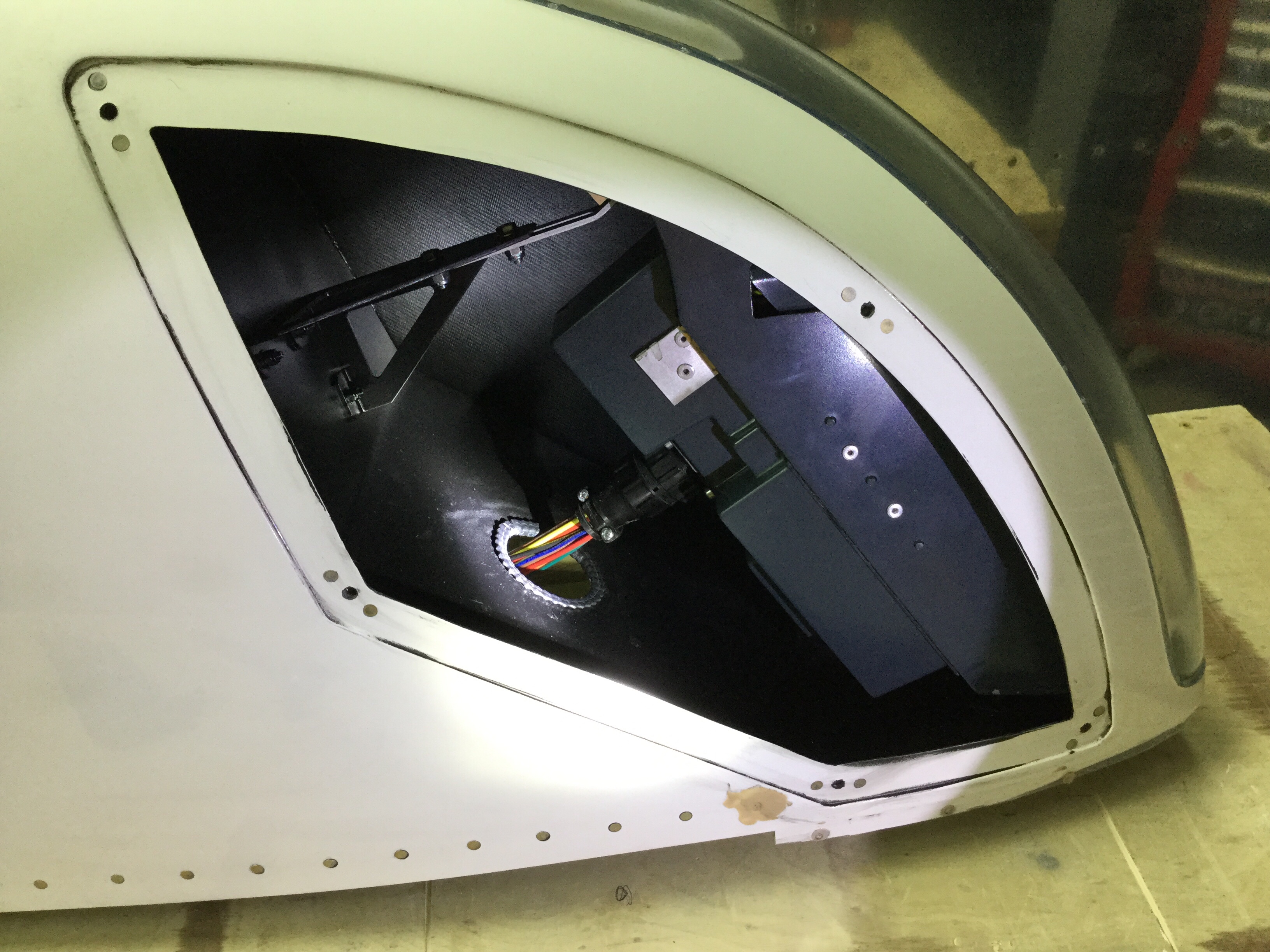
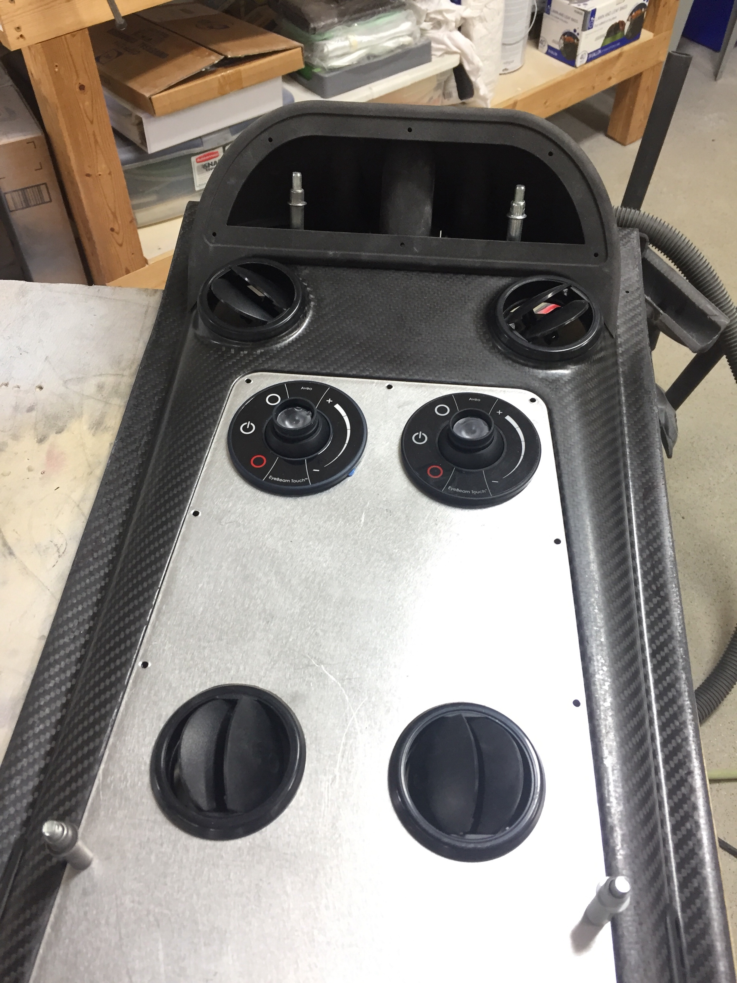
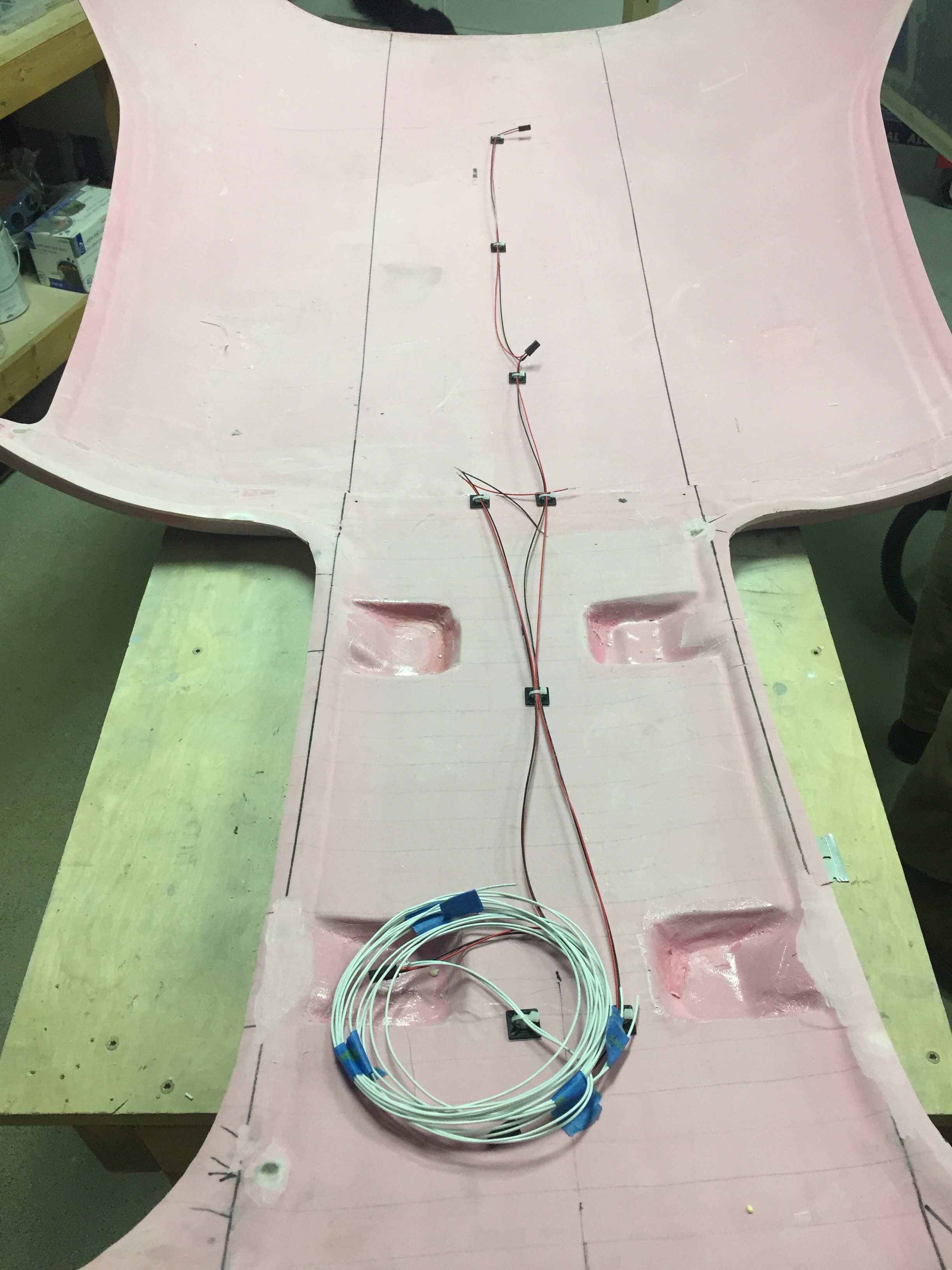
I began by taking everything apart and checking out how it was all pieced together. The first thing I noticed was the mounting plate for the fan actually covered a 1/5 or so surface area of the condenser. Additionally, the system didn’t use basic air velocity and volume principles, so it was constantly going from small to large volume spaces with many restrictions.

My goal was to facilitate air flow through the shortest path with the least resistance, thereby providing more efficient flow and better heat exchange in the condenser. I studied several factory AC setups such as the Cirrus, Bonanza, and M350 and noticed no ducting on the intake and direct exhaust from the condenser through the skin. The condensers were also significantly larger in surface area. So the new design would be to pull ambient air from the tail cone through a larger condenser via the same fan and exhaust it through the side skin within the shortest path possible. The ambient air is provided through an louvered intake near the horizontal stabilizer.

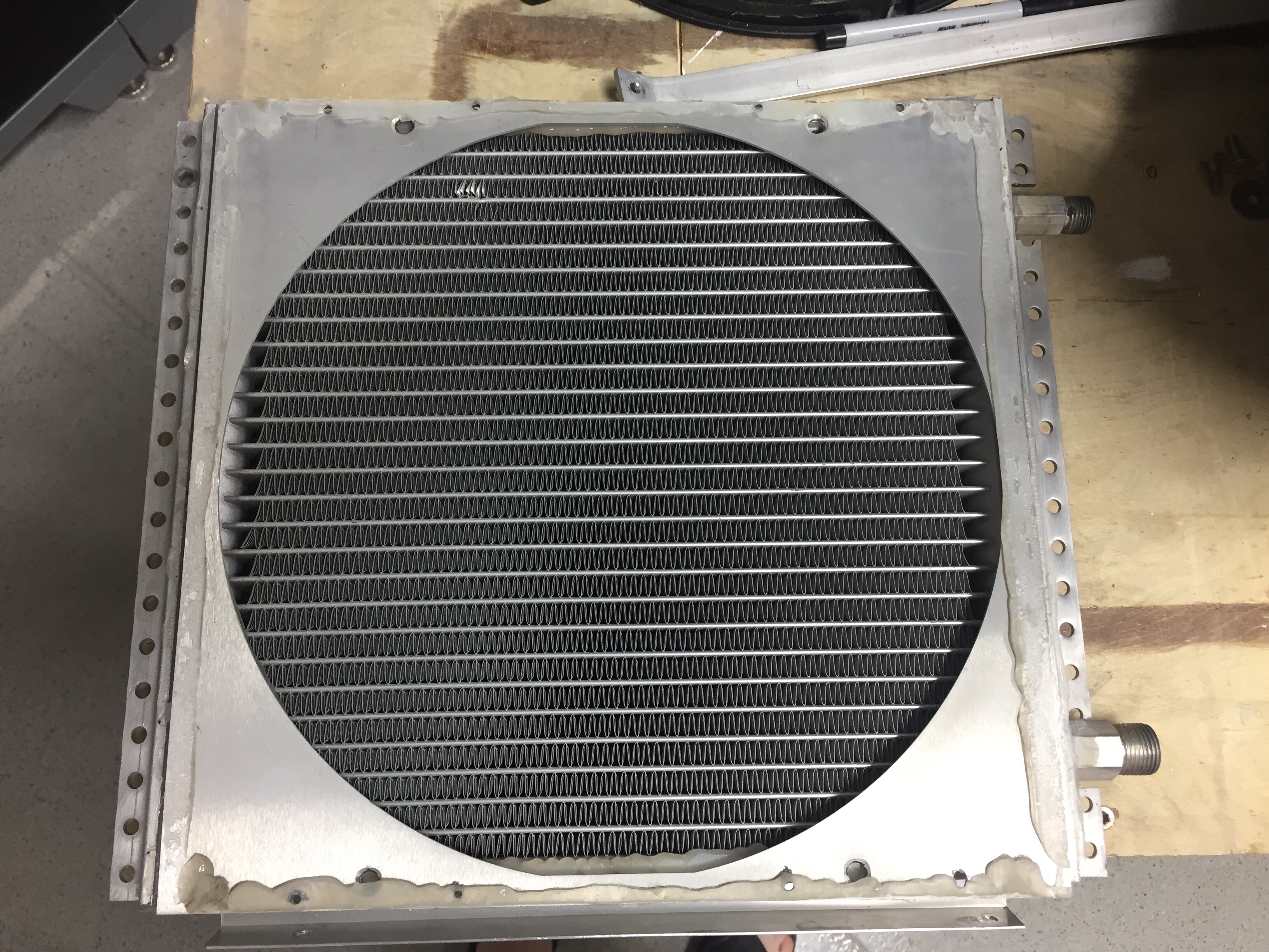
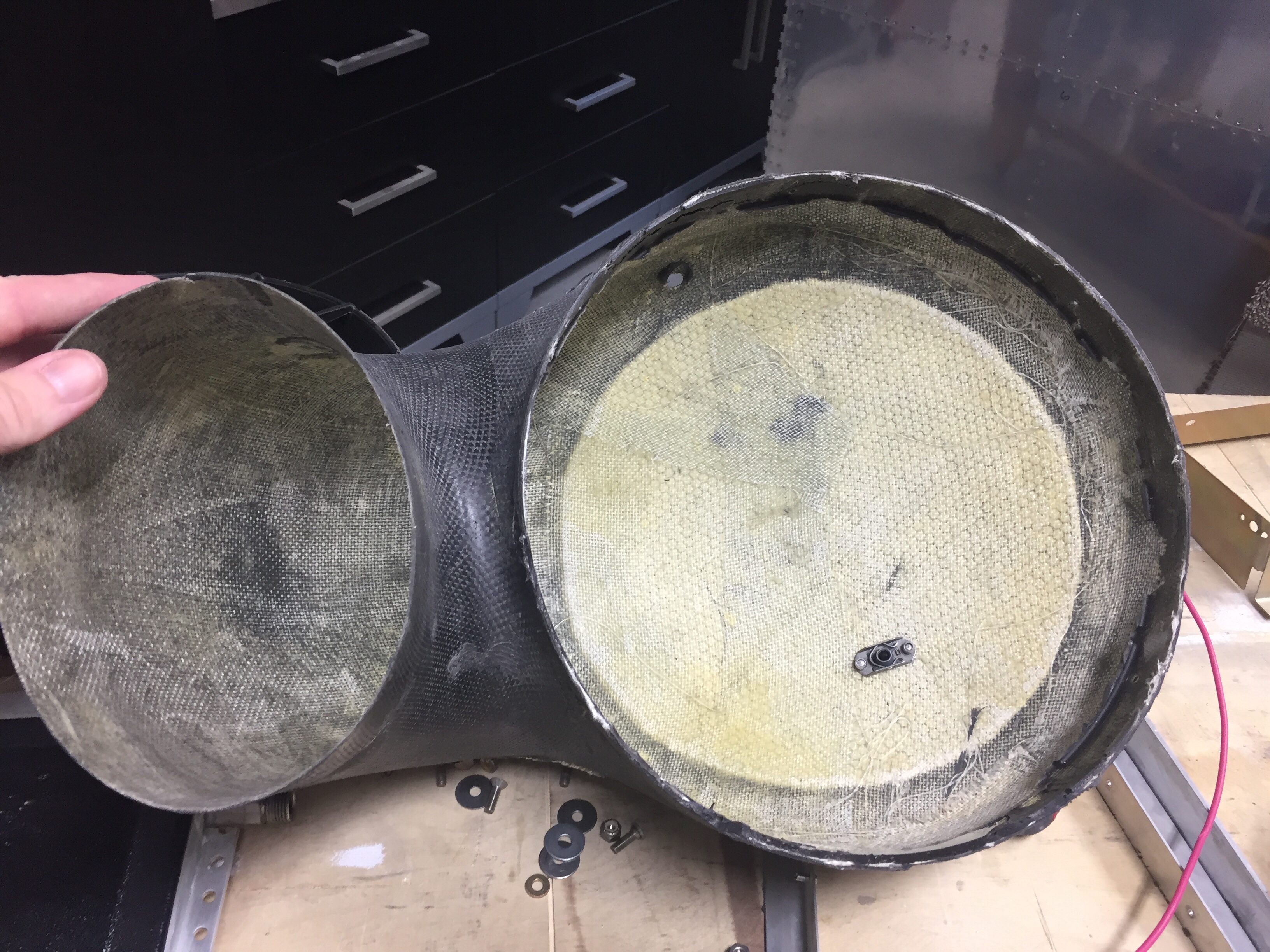
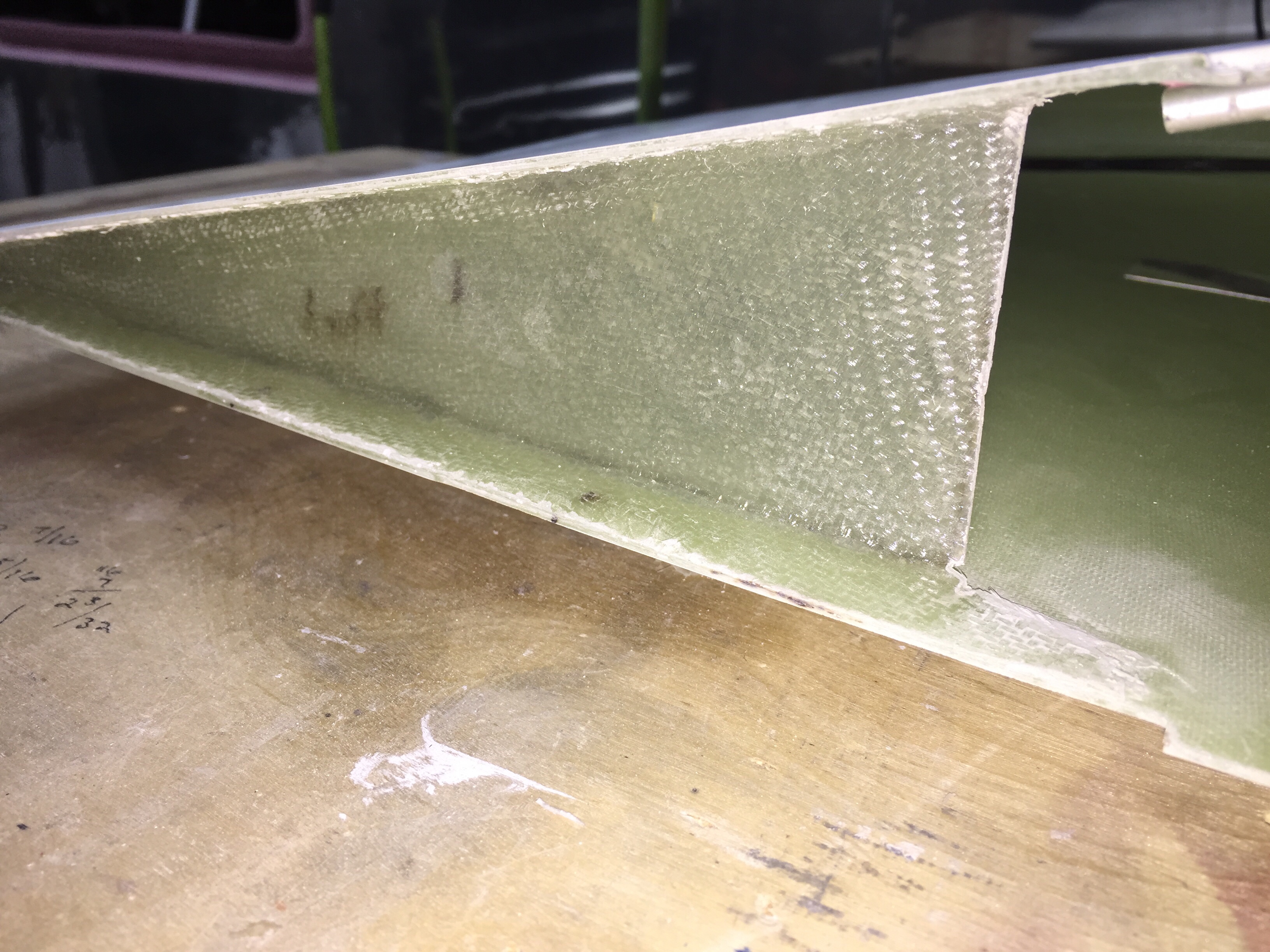
So, I bought a 16″ x 12″ condenser and set about molding a plenum from the condenser to the fan. If I had a vacuum table, this would have been perfect to keep the mold to share with others, but unfortunately I had to lay up fiberglass and the molds were trash.

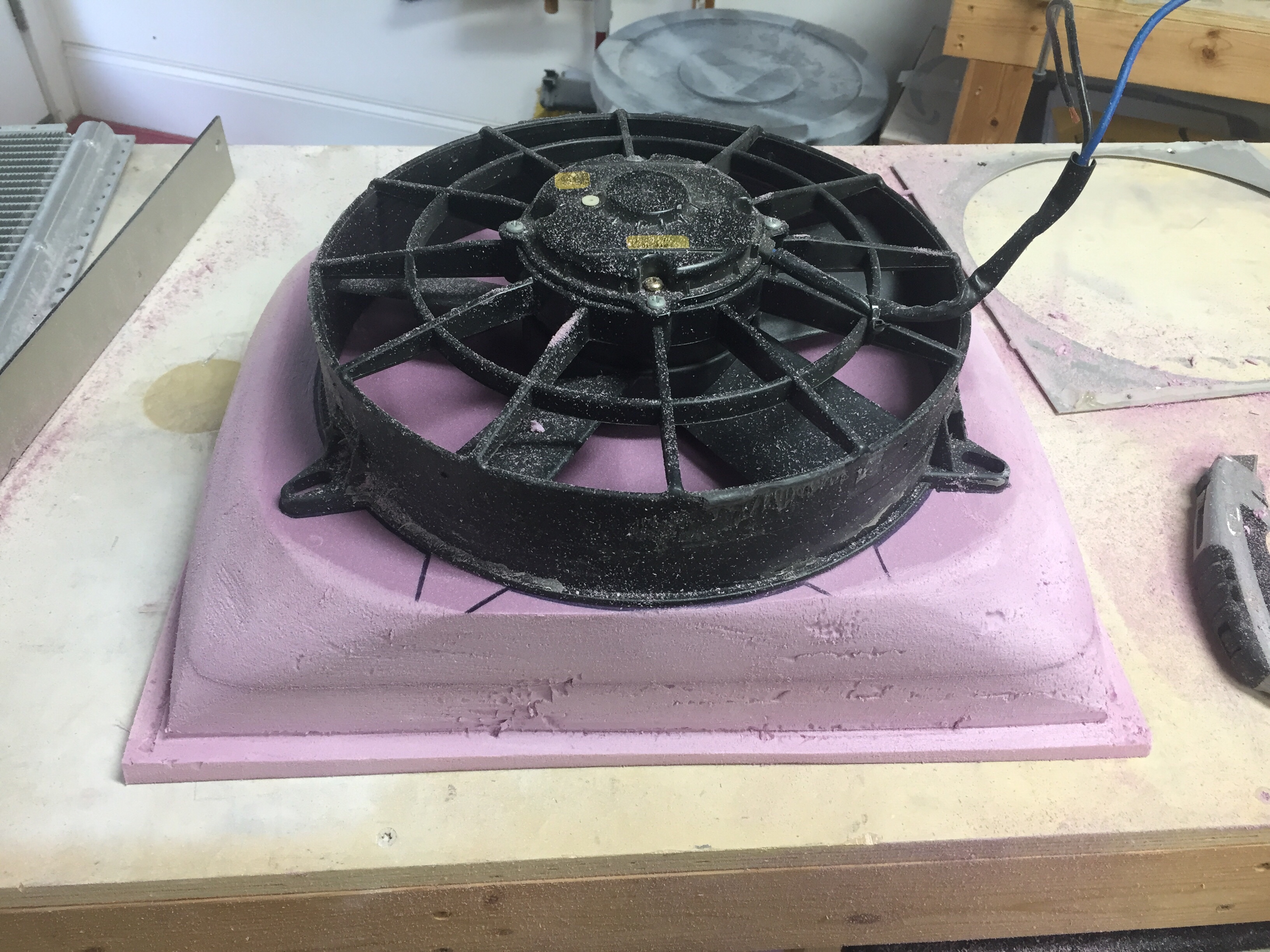
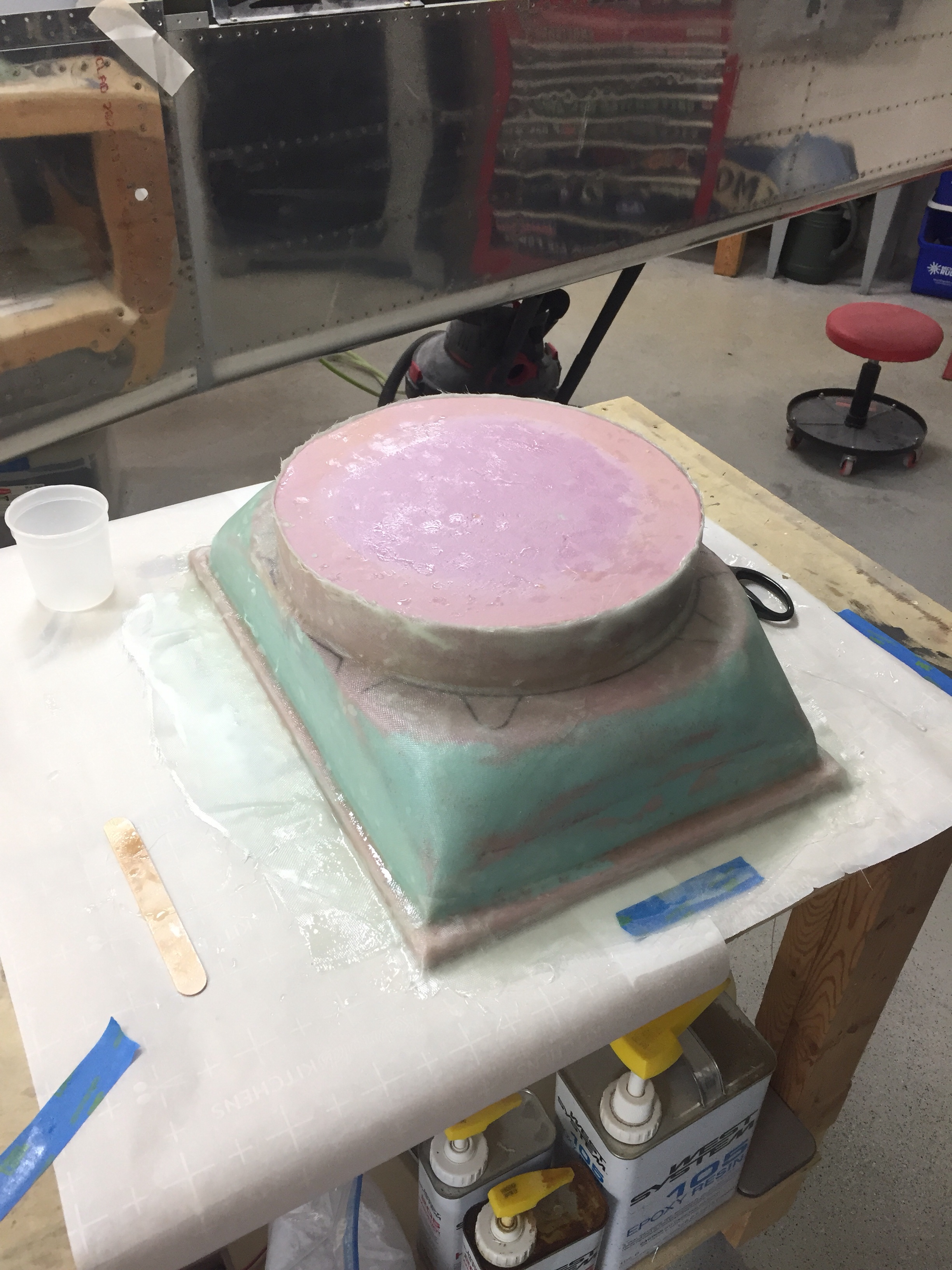
The layup came out very nicely despite destroying the mold and was a perfect fit around the fan casing. A simple bead of silicone should seal it up nicely when installed.

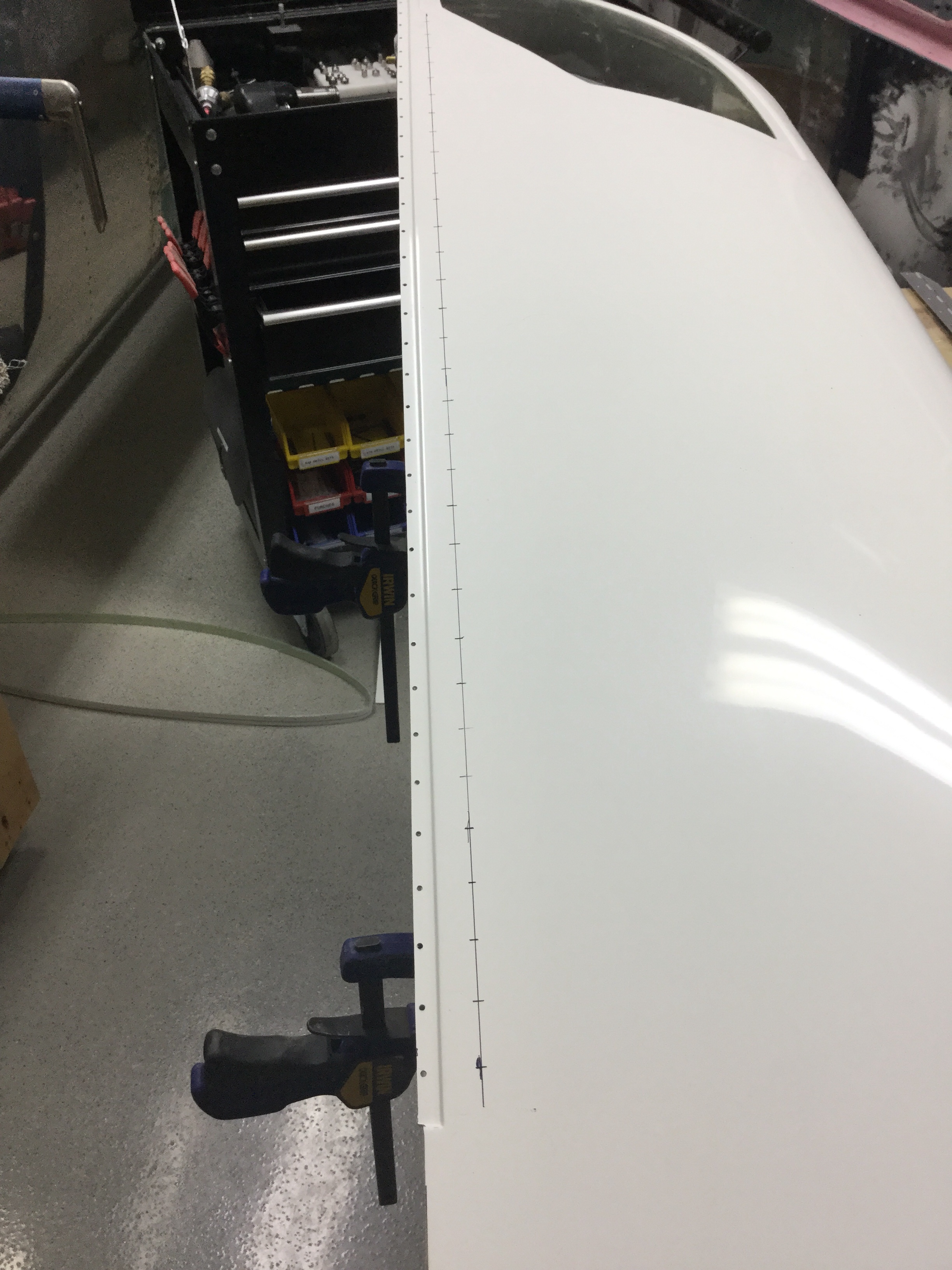
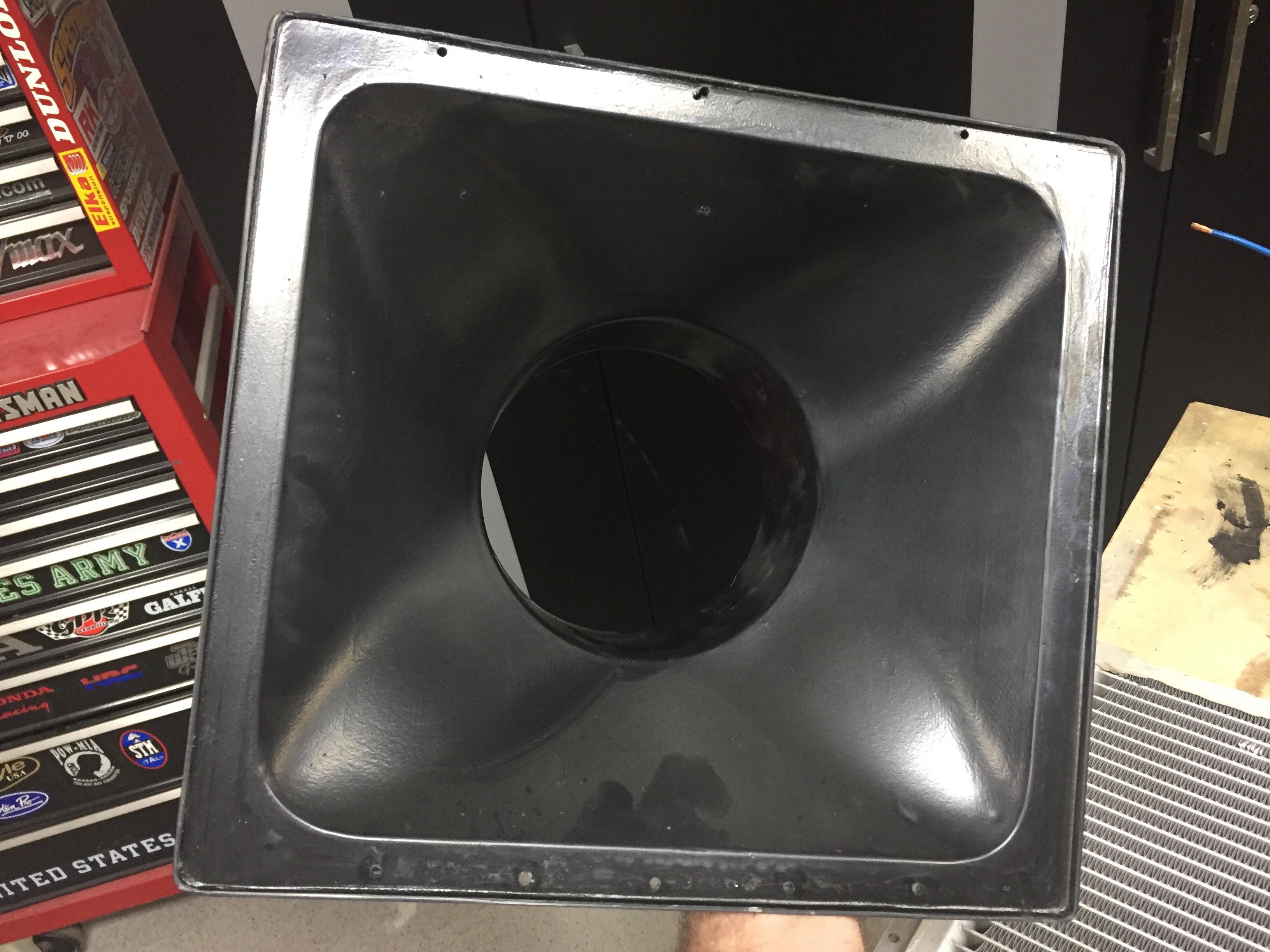
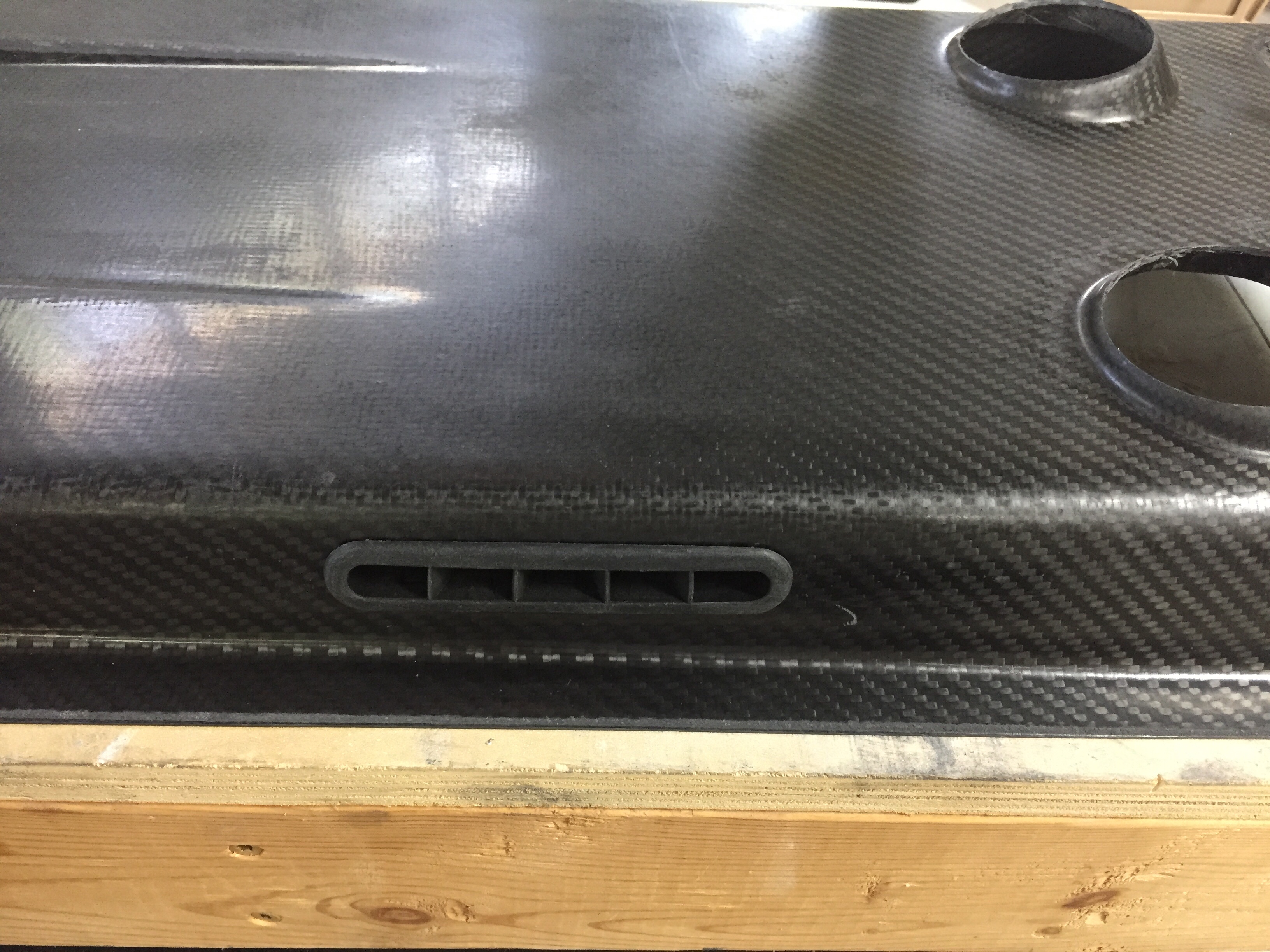
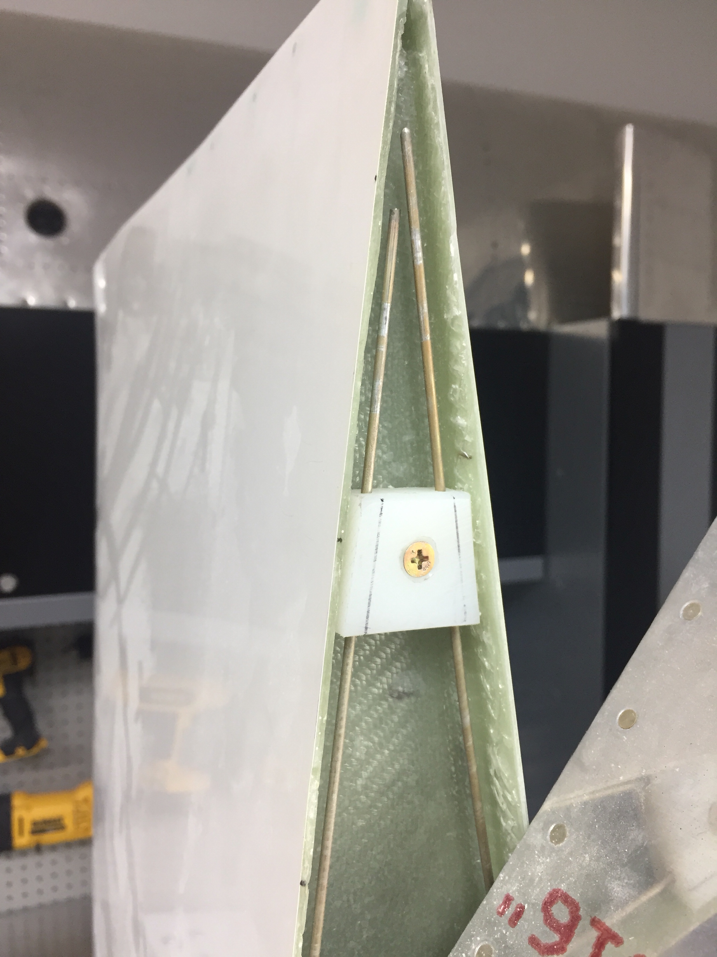
Next was to do a mold from the fan to the skin for the exhaust. I figured up the square inches of the fan and worked within the stringers to maximize the opening area while keeping it just under the square inches of the fan. My thought on this is using the Bernoulli principle and having the smallest (relative to the entire air path) opening creating the highest velocity at the skin. This will in theory help the exhaust penetrate the boundary layer air around the fuselage, which has also been a concern from others.

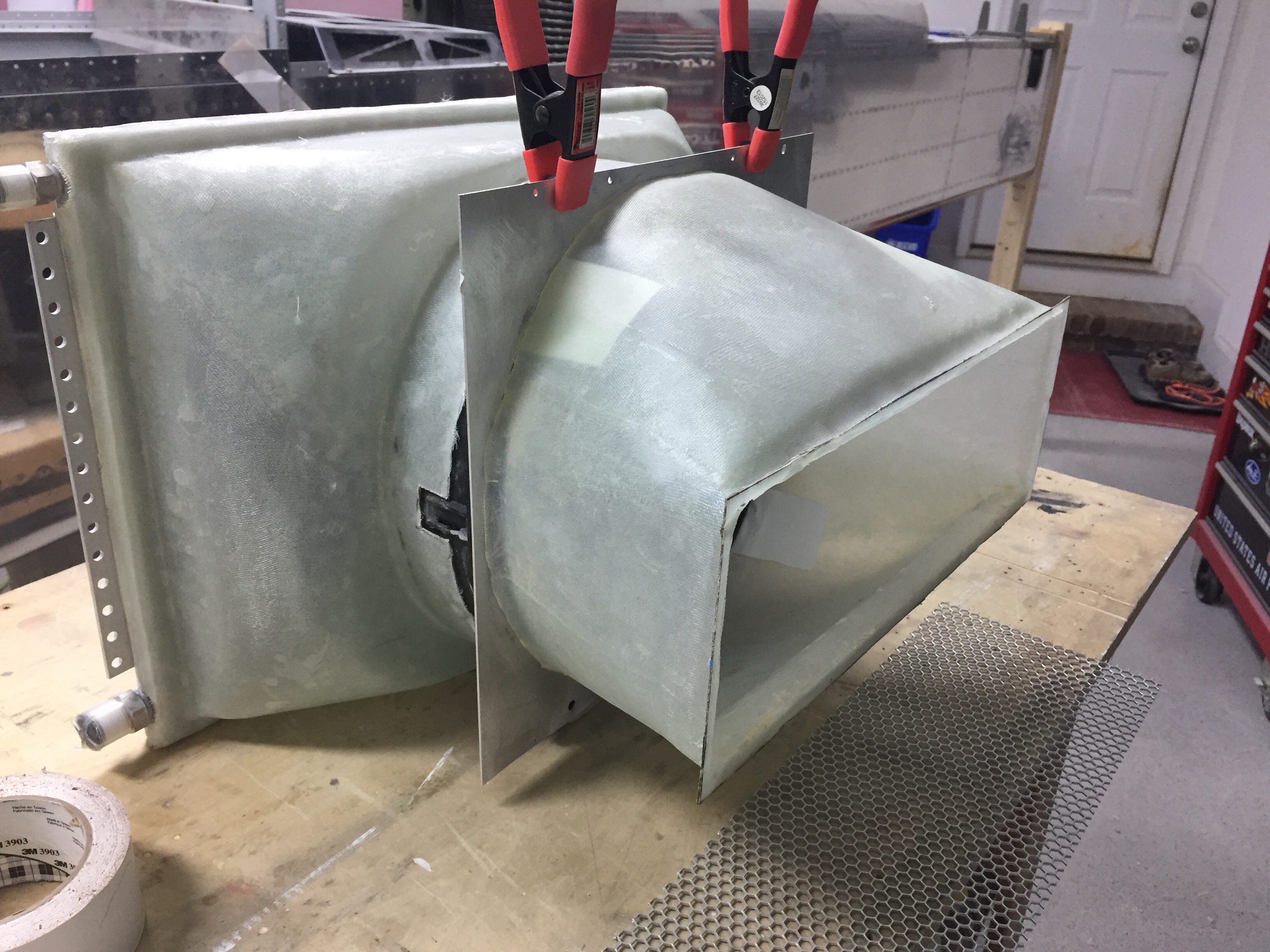
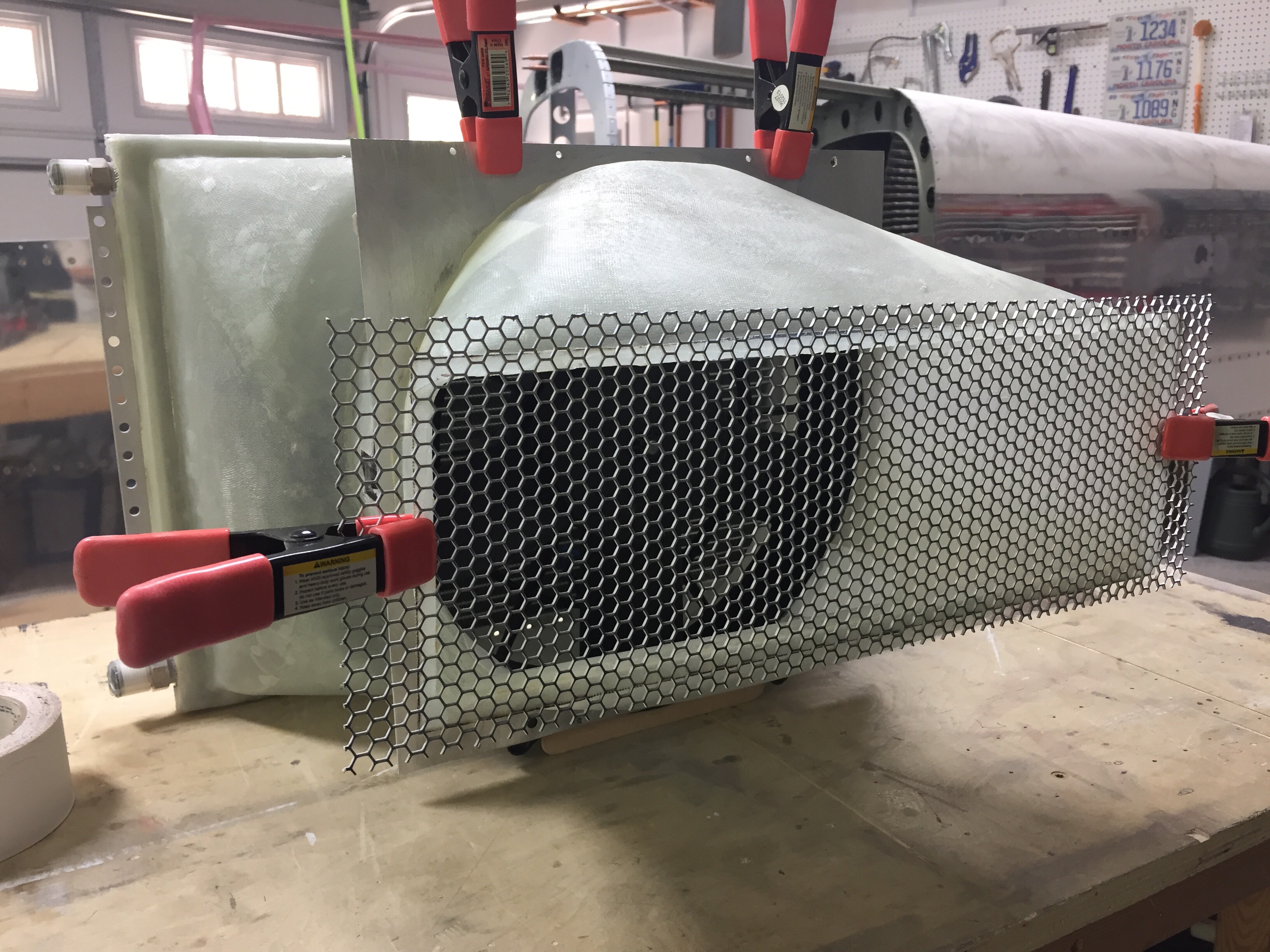
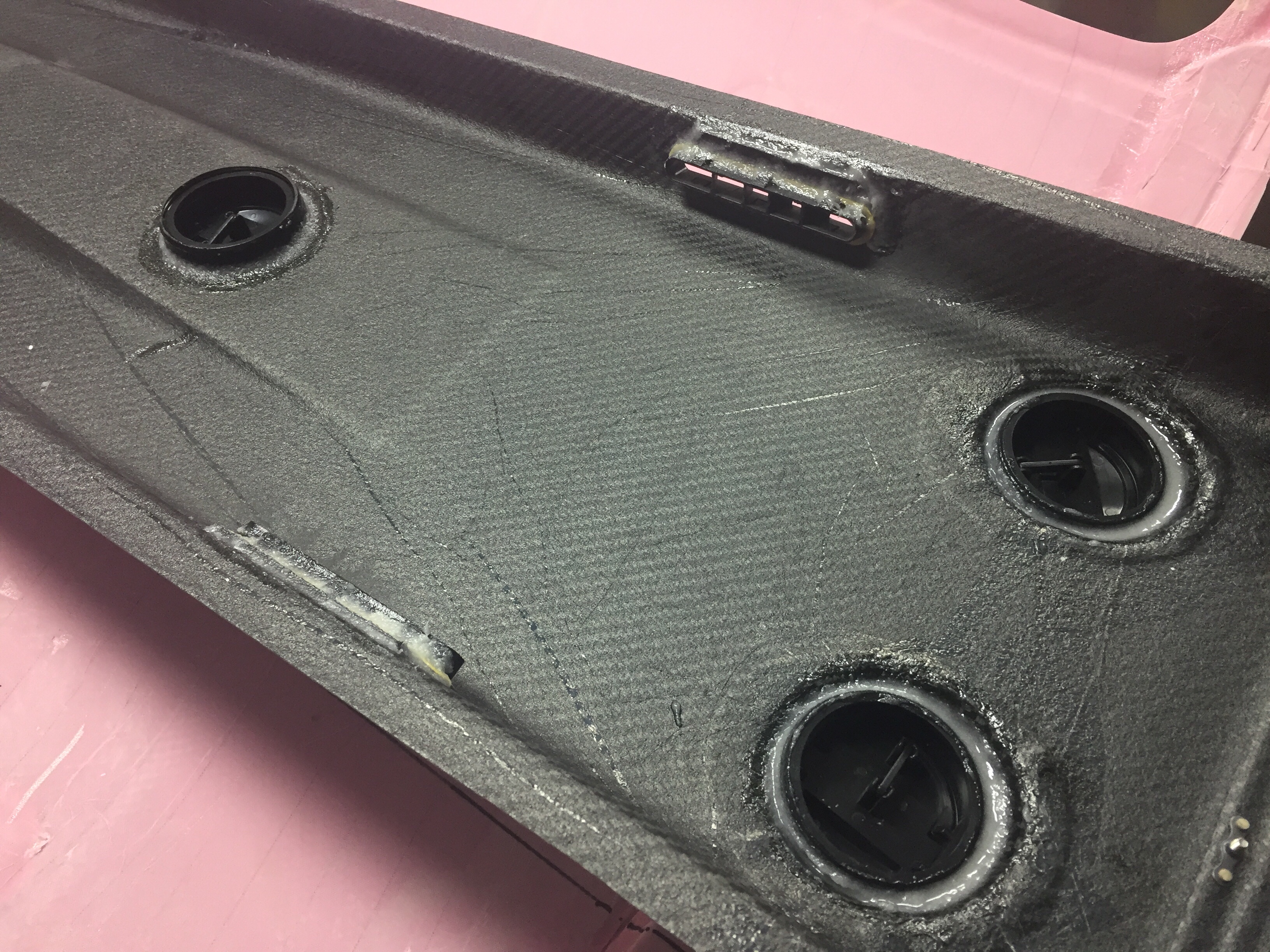
I used the same fan mounting plate since it’s no longer restricting air flow. The exhaust plenum as a lip molded in to use as a mounting surface on the skin. The weight of the setup will be supported from the stock tray so the plenums aren’t load bearing.

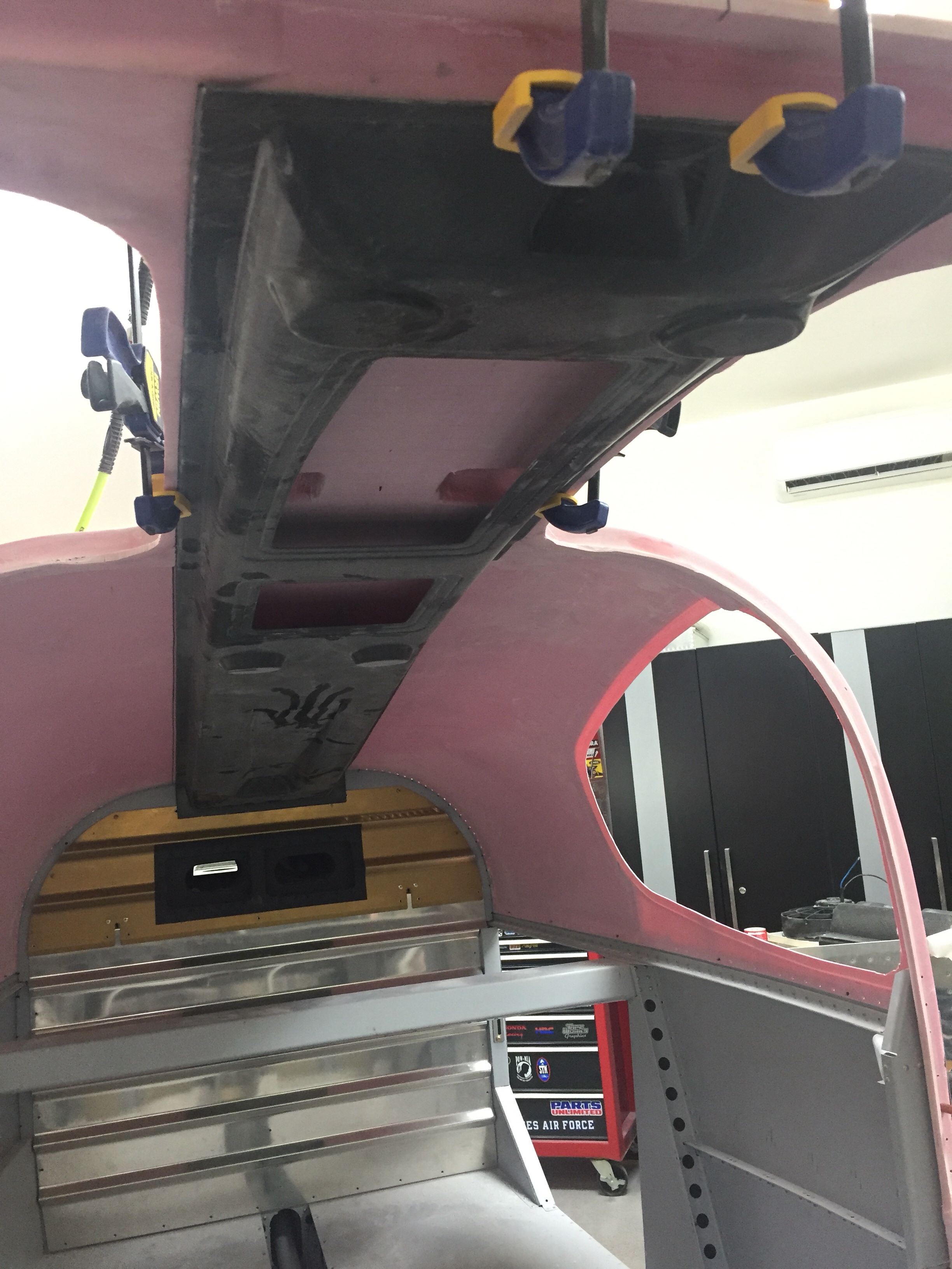
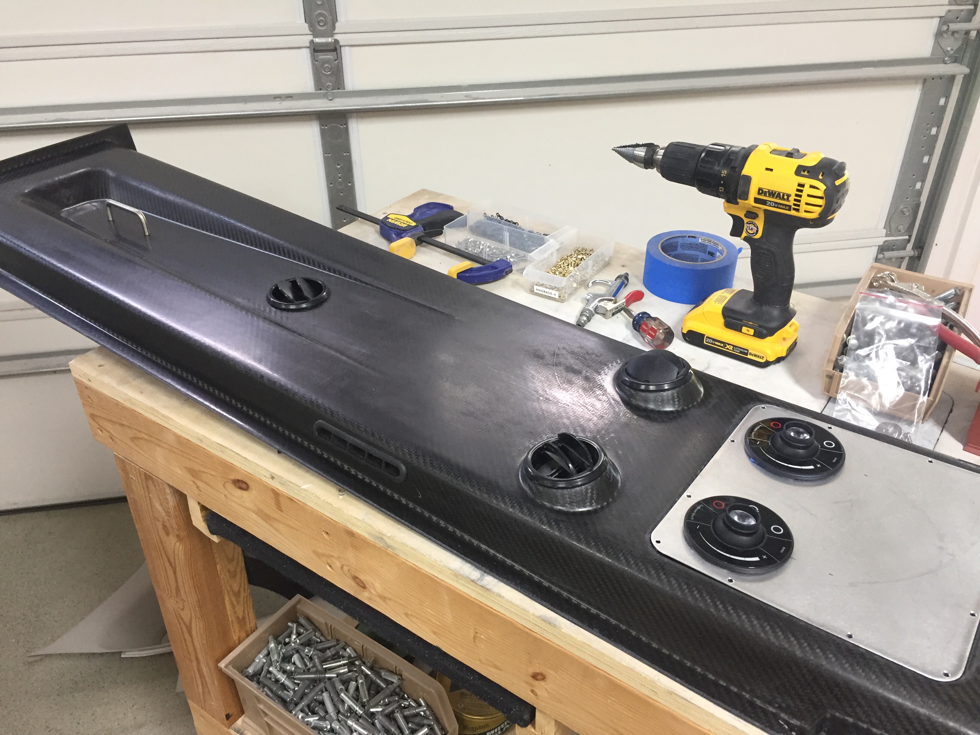
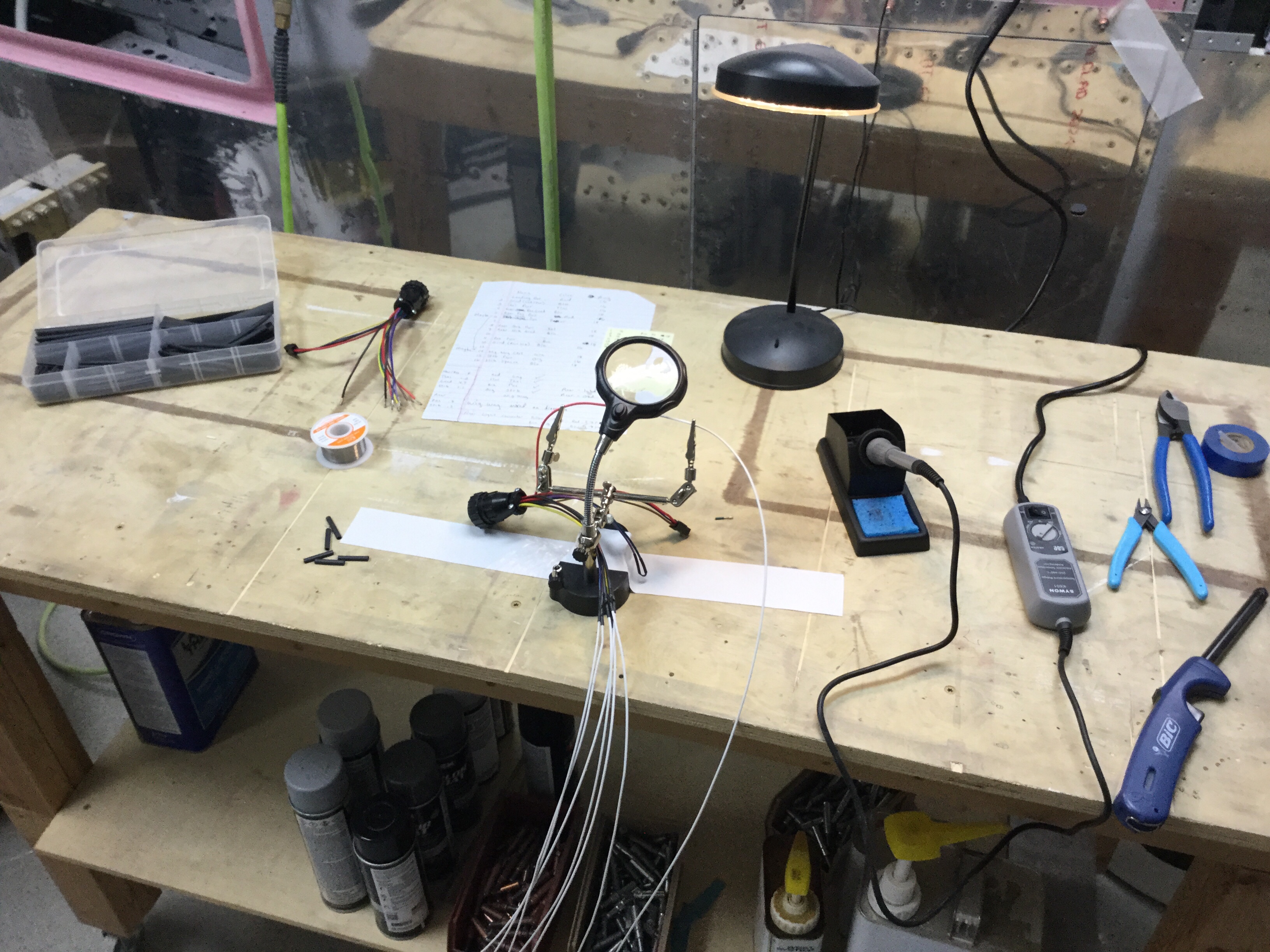
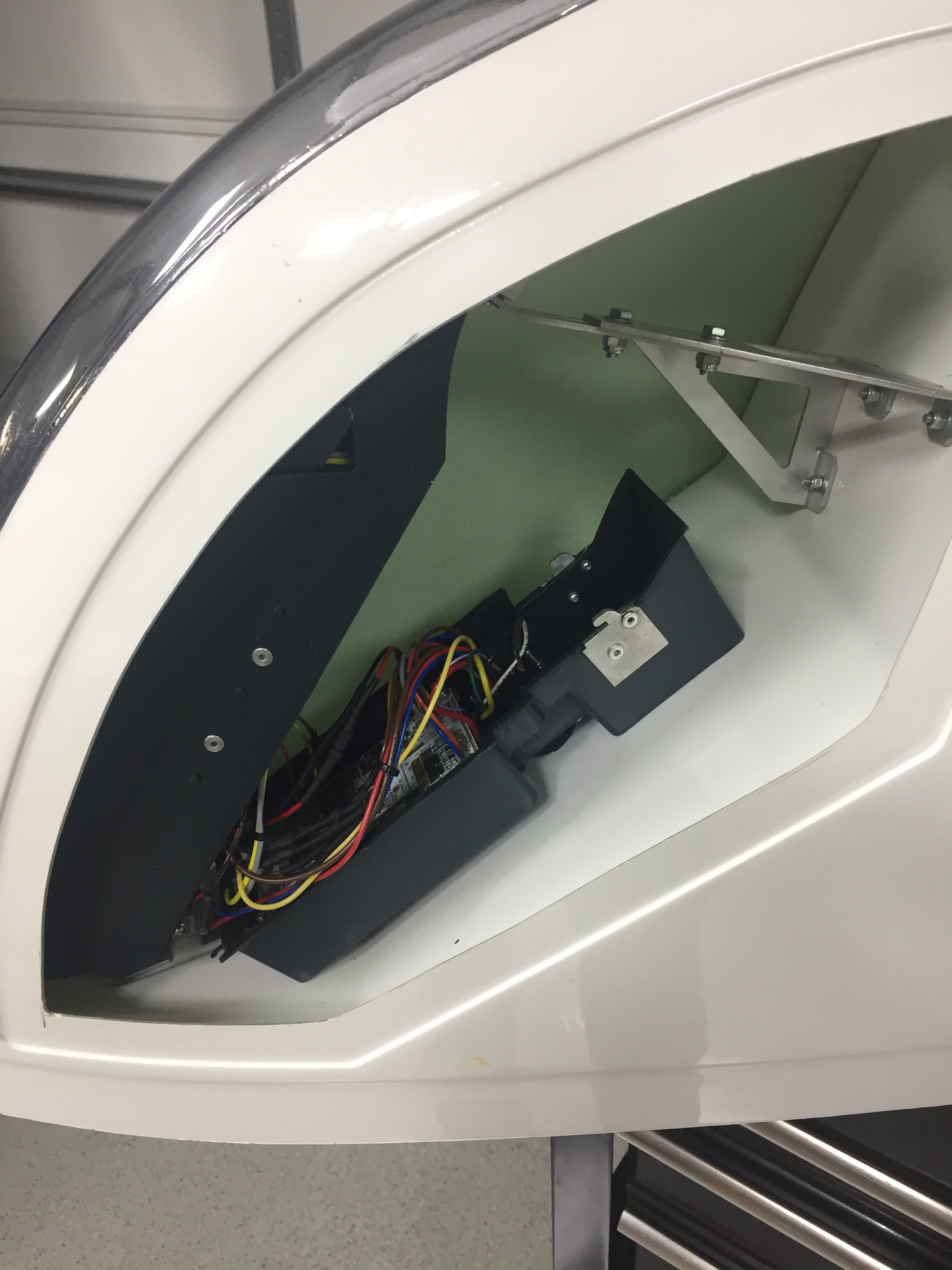
I put it all together and hooked up the fan to check it out. There is significantly more air flow going through and I’m cautiously optimistic that this will create a much better performing system.

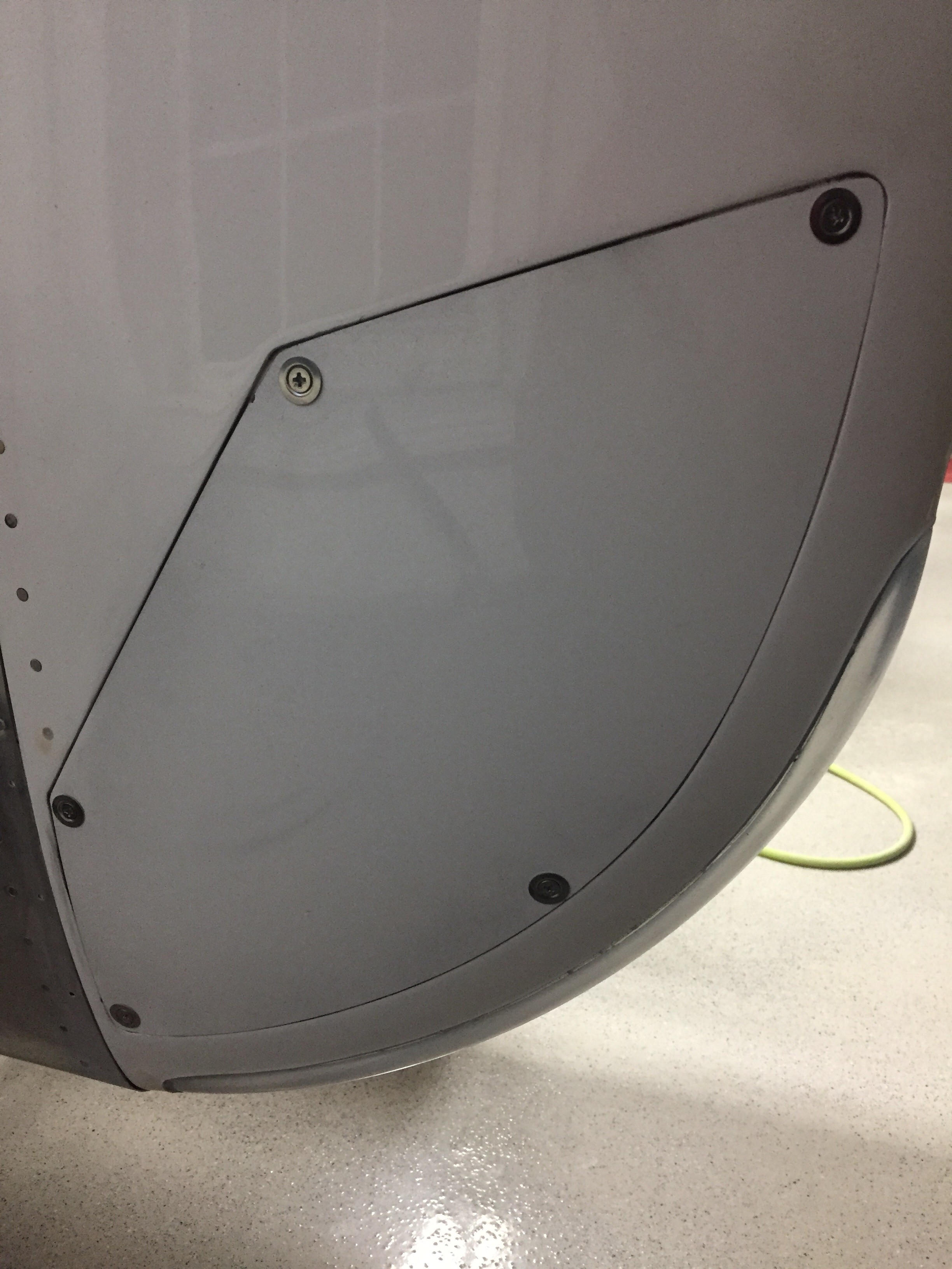
Next up will be mounting it all in the airframe and cutting the skin.

Controlling the overhead

One huge task to complete before the cabin top can go on for good is the overhead console. This piece of art comes from Aerosport and allows the vents for the air conditioning and the lights to be mounted on the cabin top. I also have one of the first production examples of the overhead switch panel that Ed Krantz molded up.

The first step is a rough fit and trim to get an idea where the interference points are. The mold they use is pretty accurate but has a few spots that needs adjustments. I didn’t have to cut the joggle around the step in the cabin top, however, there were a few spots up near the windshield that were too bulbous and had to be ground down. Overall, the initial trim and sanding was a pretty quick and painless job.

The overhead has two large aluminum panels that can be used for lights, vents, etc. but need nutplates installed to secure them. Pretty quick job to set it all up including countersinking the panels for flush screws that came out very nicely. I also decided where to mount the four curtain vents that I got from South Florida Sport Aviation. They are using the Airflow Performance set up on their own interior and despite my best efforts, I couldn’t find any vents like these online. I like these because it allows good airflow along the windows as well as alternate airflow if one or more of the vents are closed, keeping good flow through the cabin and over the evaporator which is key to efficient performance of the air conditioner.

I also used the four molded spots to mount air vents in as you can see the cutouts above. Most have used either the eyeball vents or a universal car vent. Based on feedback from others and the astronomical price of eyeball vents, I decided Summit Racing vents would work better. They were $20 each instead of $120 each and I think will allow a lot more air to flow while being easier to use. I simply used epoxy/flox to secures them to the overhead taking care to not have any leak on the vents themselves. I also put two vents in the metal panel so that the pilot and copilot each have two vents, hopefully keeping me cool up front with all the glass. The panels will also hold an Aveo Eyebeam Touch task light for each seat.

Lastly, I installed the coat hanger in the rear which will probably rarely be used, but hey, it’s part of the kit and looks good. I can also use it to call this a business aircraft!

I will be running the wires for the switch panel and the task lights up through the center post so wanted to get the wiring that will be in the overhead completed. I went ahead and made up the wiring harness for the four task lights as well as the three overhead dome lights that will be used for general cabin lighting. The pictures show bare contacts, but after another order from Mouser came in, I installed the Molex connectors so that everything is line replaceable without cutting wires. I also cut the three holes in the overhead for the lights.

Finally, after one complete evening off of the cabin top to clear my head and make sure I’m not forgetting anything, it was time to epoxy it on for good. I mixed up a healthy amount of epoxy/flox and fortunately had a friend to split the task of spreading the mixture and setting it in place. With a couple of clamps and clecos, it fit well and made a secure bond to the cabin top.

Next up will be shaping and filling the assembly to get it all prepped for paint and final instal.

Wired for moving day

With the tips fitted to the wings, it’s time to run some wiring and finish up the wings. I integrated the Archer nav antenna into the tip mounting hinge which thus links the antenna to the wing for a proper ground plane, per the plans. I used a few pop rivets through the bottom of the tip to secure the antenna in place. I wanted to make the tips easy to remove, so I used bulkhead BNC fittings for the coax on both end of the wings.

I also ran the wires from the trailing edge position / strobe light up towards the main lighting modules and installed a micro fit connector so that the lighting module can be removed for future maintenance / replacement should the need arise. Again, all of the wiring has been documented in Visio including pin outs on each connector so I’ll be able to reference it long after I’ve forgotten how or why I did it this way!

I used CPCs for the main wiring runs and am very pleased with the setup. Some folks avoid connectors like the plague, but I don’t see them as failure points if they are done right and properly tested / treated. I checked continuity of each wire after running them all so I know everything is ready for plug and play. The wing root connectors include those for the pitot heat and AP servo on their respective wings. The aileron trim servo is on it’s own micro fit connector due to the small wire size. I’ve gotten really proficient at the micro Molex connectors and really like them.

I also had to layup a small rib on the trailing edge to not only support the shape of the tip, but also provide a mounting surface for the hinge pin retainer. I used a trimmed block of delrin and nutplate to secure the pins. This keeps the pins inside the tip profile and thus unable to work themselves loose. They also butt up against a stop on the leading edge. I didn’t want to put a bend in them, as it’s very easy to use a drill and spin them in / out.

The only system component not installed in the wing is the OAT sensor which I’ll get with the avionics in a few months. That’ll be simple to put into an access plate and a string is still waiting to pull wires through the wing root.

Since the wings are all complete, I need to get them out of the garage to make way for the finish kit and make me feel like I have real airplane parts in a hangar. My Diamond bros graciously offered a corner of their hangar for me to store the wings in until our hangar is available. So moving day came and anticlimactically went! It was like I designed the wing rack for the trailer and with Ron’s help, they rolled right on and off. We used a few tie downs and took our time on the 10 minute drive to the airport with no damage reported. I hope the fuselage move goes this smoothly!

Bonnie the Bonanza is now babysitting RV wings. Meanwhile, back home the shop has so much room for activities such as finishing the cabin top and getting ready for the finish kit and cowling which are due to arrive early August.

Success hinges on the tips

Some time ago, I received a large package from Aveo containing a brand new set of their ZipTips, wing tips with slick looking LED’s. I’ve been waiting on these things for years, ever since I saw them at Sun ‘N Fun in 2013. I’ve hounded poor Damien at Aveo relentlessly but it paid off with an opportunity to help them out with profile shaping and some prototype testing. In the end, I think it was worth the wait and I’m really looking forward to seeing these things all completed.

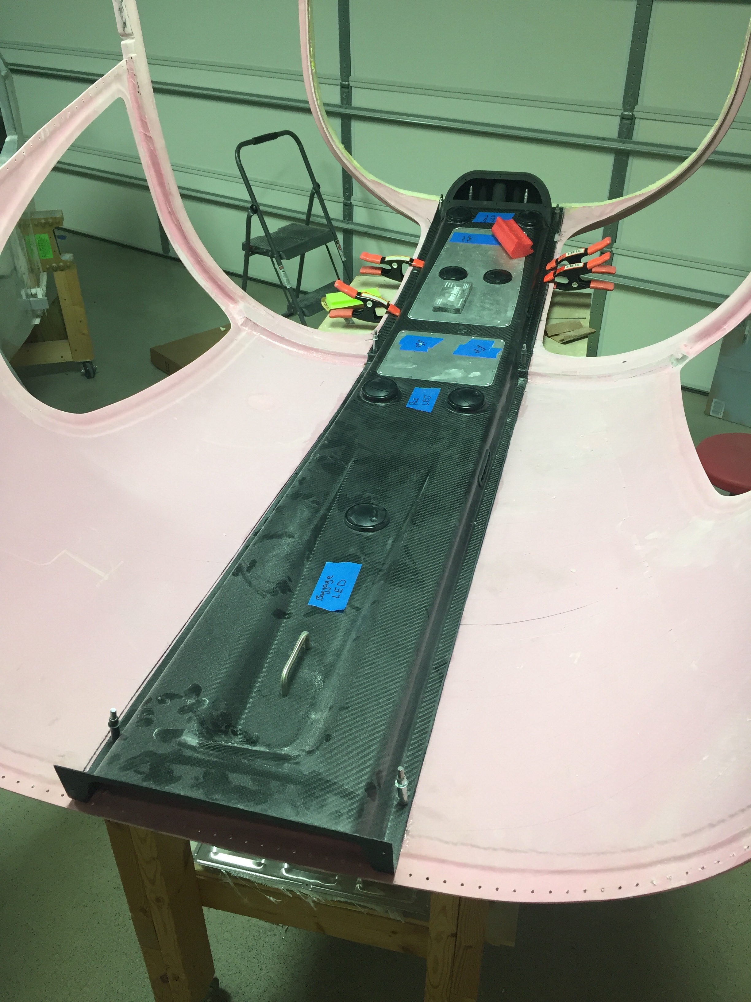
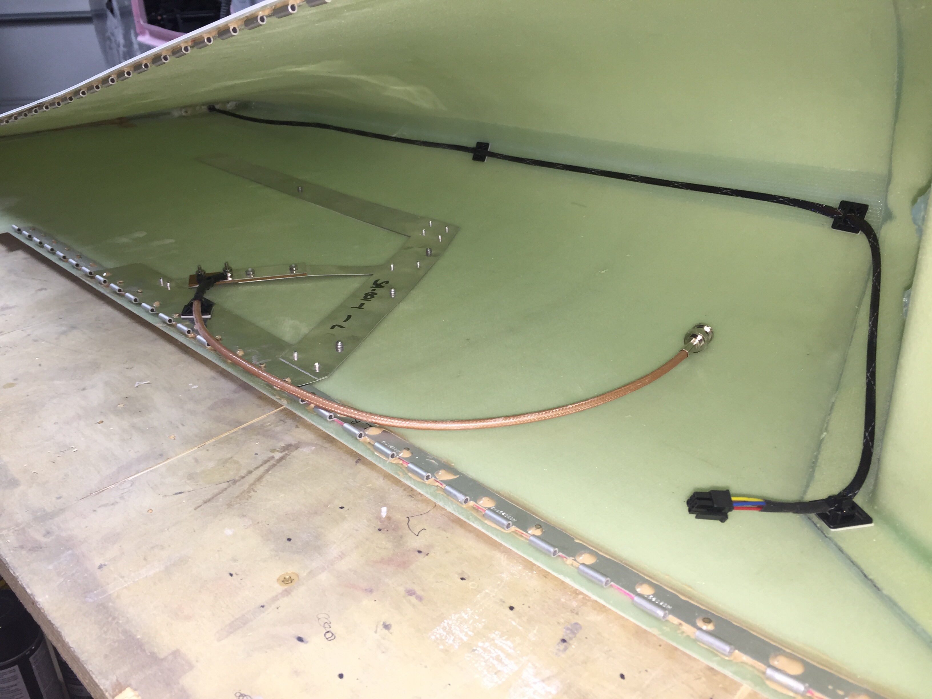
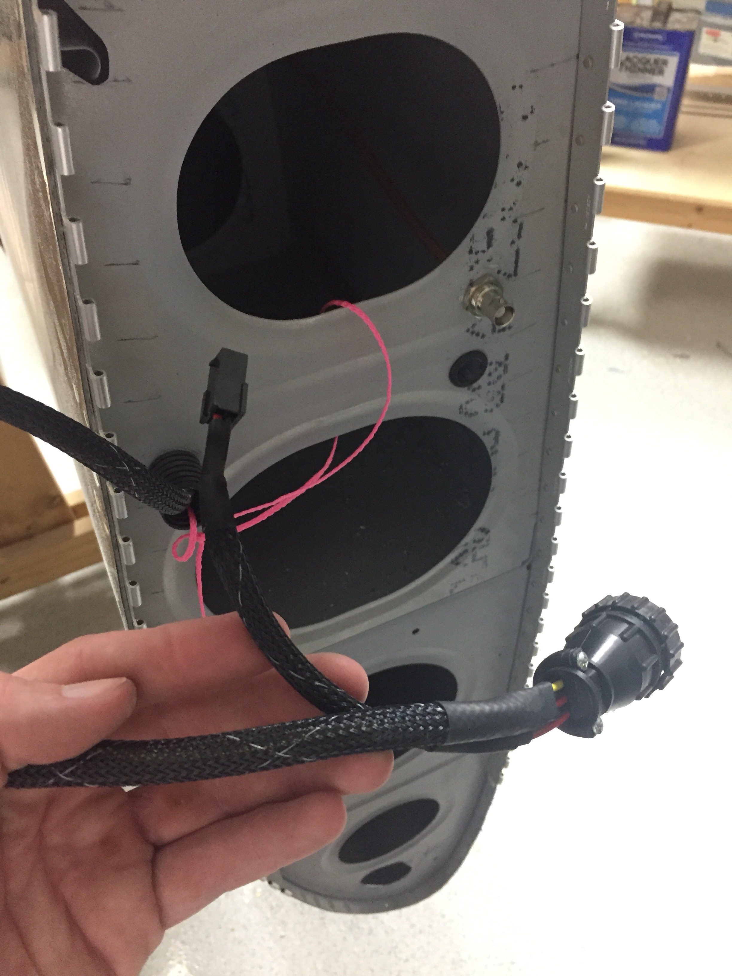
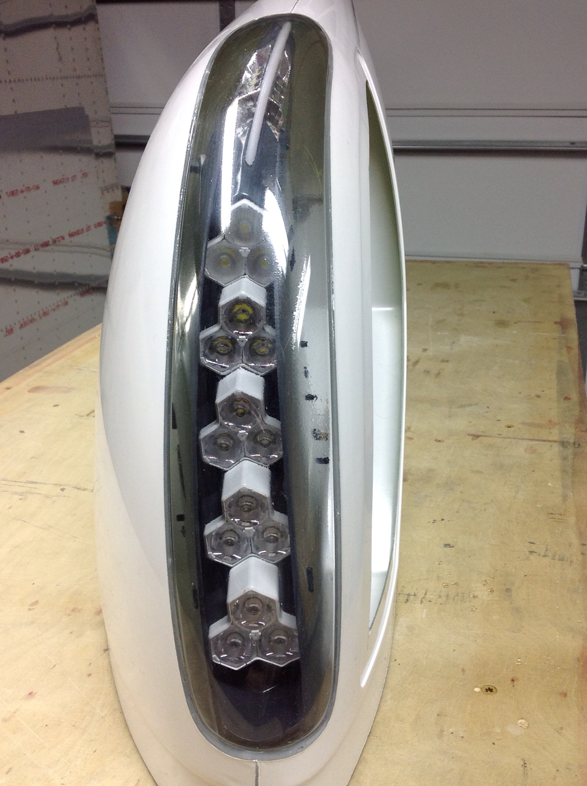
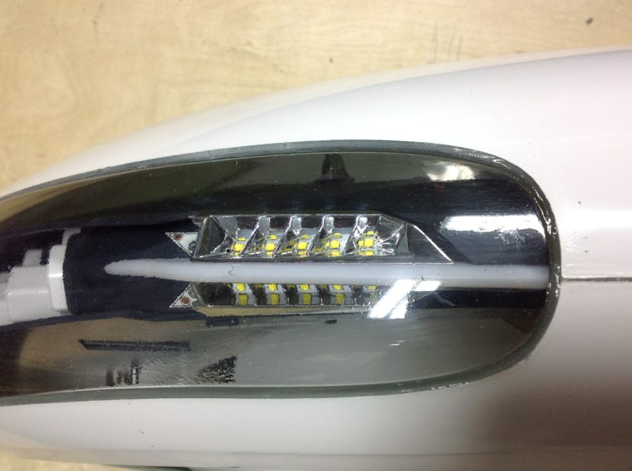
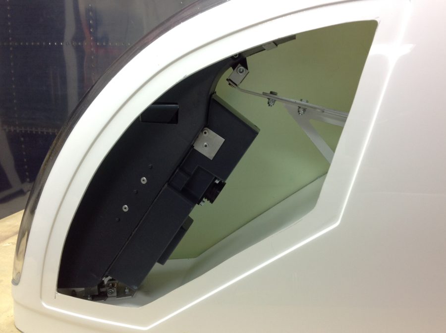
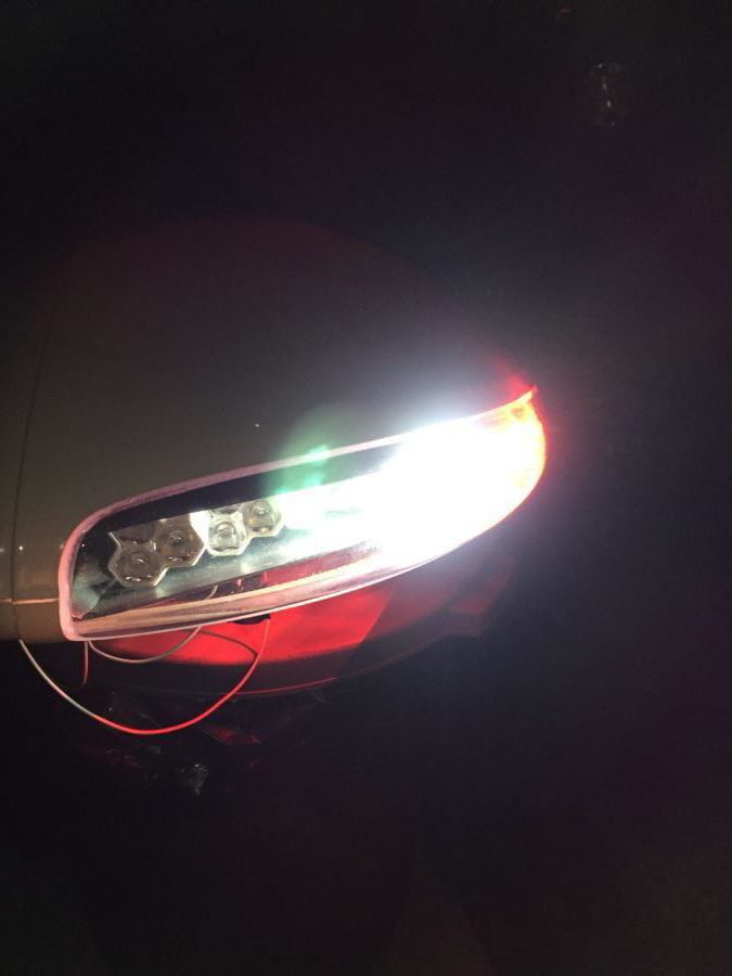
Now, because I was helping out, I received the prototype of the light modules and to say it nicely, they’ve been through a tough time. Unpacking the box, there were a few things rattling around and the back of the light module had come off.

First order of business was to test out the light modules. There is a 16 pin CPC with pigtails included, but the wires weren’t pinned out accurately causing me a few scares that I had shorted out the board or LEDs. After a few emails and testing, I was able to re-pin and document the proper wiring schematic. I did this for both sides and then took the time to re-seal the modules closed using some silicone and fresh hardware.

As others have said, these things are crazy bright! I hooked them up outside just to see what could be lit up and man, I am really impressed. Pictures and video don’t really do justice, but let’s say that I’ve flown many Pipers and Cessnas that have less than half of even one of these landing lights. Combined with the Aerosport taxi light, I think I’ll be able to light up the night just fine.

After testing, I started to do a rough fit and trim, but then they got put to the side waiting on the piano hinges that I planned to use to mount them. A year later, it’s time to finish them up so that I can call the wings complete. The first step was to complete the trim using the methods followed by others to install the tips with hidden piano hinges instead of screws and nut plates. I won’t go into detail as it’s documented on plenty of other build logs and forums out there such as VAF. Taking my time, I was able to get a really nice fit and used the cut off wheel on a die grinder just as I did with the cabin top.

I did run into some interference with the light module mounting hardware that butted up against the end rib. After talking to Van’s support, I drilled an accommodating hole in the rib to allow the hardware to protrude inward through the rib and let the tip sit flush against the skin. Once I had the hinges on, I split the trailing edge to reposition and line up with the ailerons. This is a common practice, even on the stock tips and was fairly straightforward. After a bit of work, I had a nice straight line from flap to tip.

Finally, I received some stainless steel hardware in for the light module access covers and mounted them with nutplates. Others have used a lot more fasteners than I did, and I’ll probably go back and add a few more before first flight. I painted the inside of the light area black to give the lights a meaner and cleaner look. I also painted the outside of the light reflectors, again, just for cosmetic purposes. Next up will be to run the wiring through the wings, mount the archer antenna, and make a pin retainer for the hinges.

Removing museum pieces

Parish came over for a pizza dinner with the wives and we managed to extract a museum piece off the ceiling.  The big pink thing that folks have asked about for the past three years is finally part of the airplane!  With his help, I did the initial trimming of the door frame and longeron area using the cut off wheel on the die grinder.  While it did produce some dust, we were outside and it really wasn’t a bad process. The scribe lines were pretty accurate where they were visible, but there were quite a few places the line was way off or missing all together.

I initially trimmed the side skirts and door frame area just to get it on the fuselage. I had to take it on and off a few times and looking back, I wish I had thought out the process a bit better. You could measure the frame and make your own marks then do a final trimming. Fortunately, the top is mounted in a bed of flox so other than some sanding and contouring, it will be fine to have some gaps such as mine around the frame.

I had considered doing an overhead pulley system since I knew it’d come on and off, but really it’s not too heavy and I’ve found a good system of crawling inside and lifting the top up with my shoulders. Then I can put it on the seat rail and spar while I get out of the plane to lift it through the door frame onto the table. All in all I think I took it off about 10 times before it was all trimmed up.

It’s really cool to see all of this together. The thing actually looks more like a plane (or at least more of a plane) than it ever has. The back seats are really roomy! Next up is trimming the window openings, door flange, and windscreen flange.