Stabilizing success

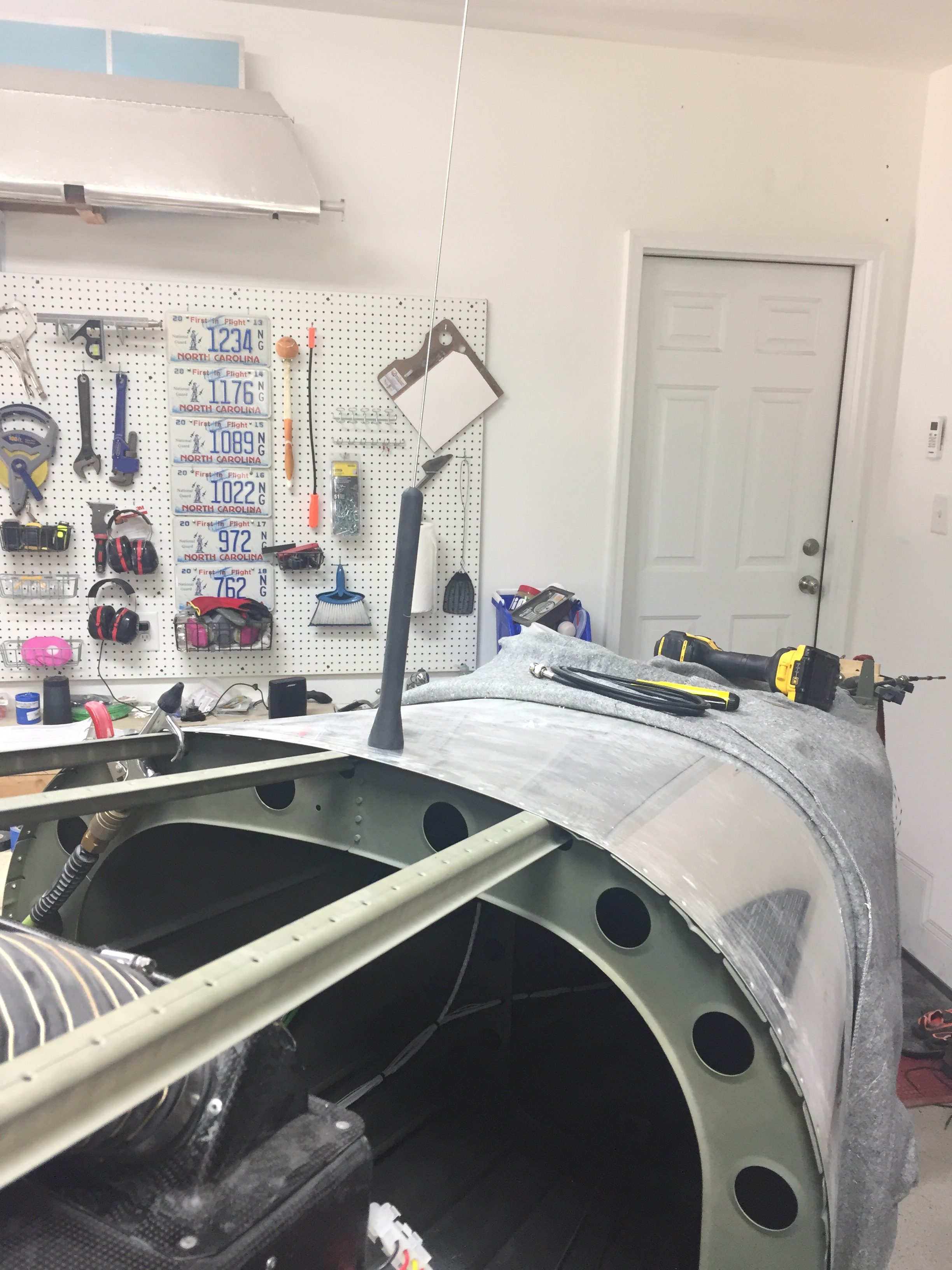
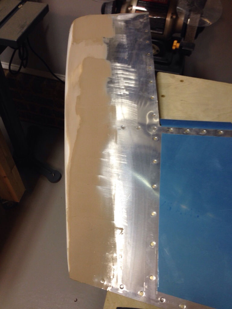
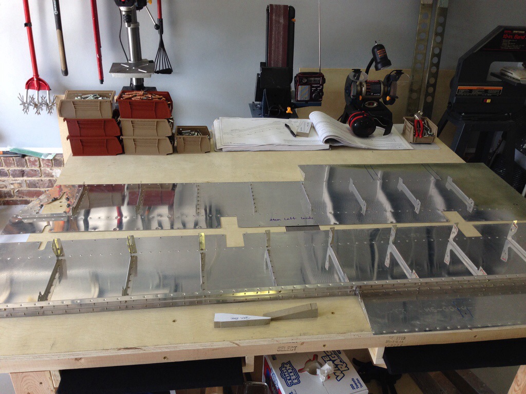
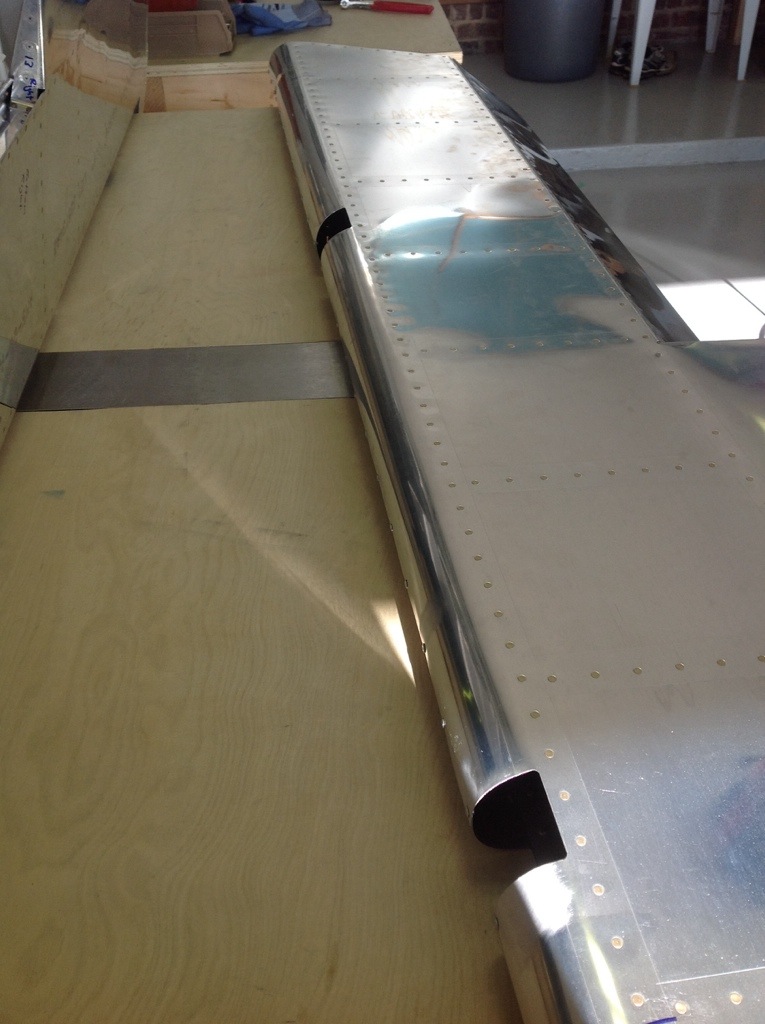
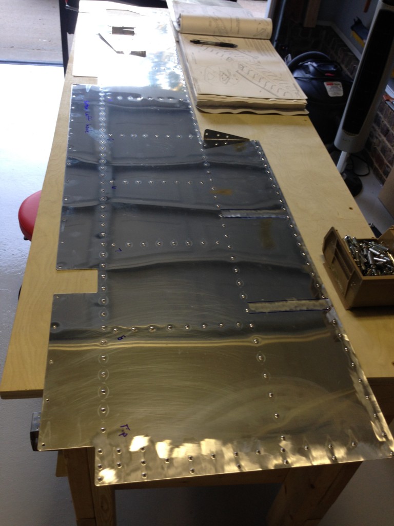
I skipped a major step during the tailcone build sequence by never installing the horizontal and vertical stabilizers onto the tail cone. I didn’t see a point of doing that in the garage just to take it all apart again for storage for years. Now that I’m in the hangar and have the room, no excuses are left. I didn’t build either stabilizer, as the original tail kit owner built them. After looking over them and cleaning them up, I “touched up” a few of the rivets I felt were under squeezed. They aren’t primed on the inside either but even after 10 years of sitting around, they are looking good and corrosion free.

The process went as planned and I spent the better part of one full day getting it all drilled and bolted on. I had purchased the CNC brackets from somewhere to mount the horizontal stab so I didn’t have to make them. I have no clue where I got them from, however, as I bought them on a whim years ago. Either way, they’re nice and you should buy them.

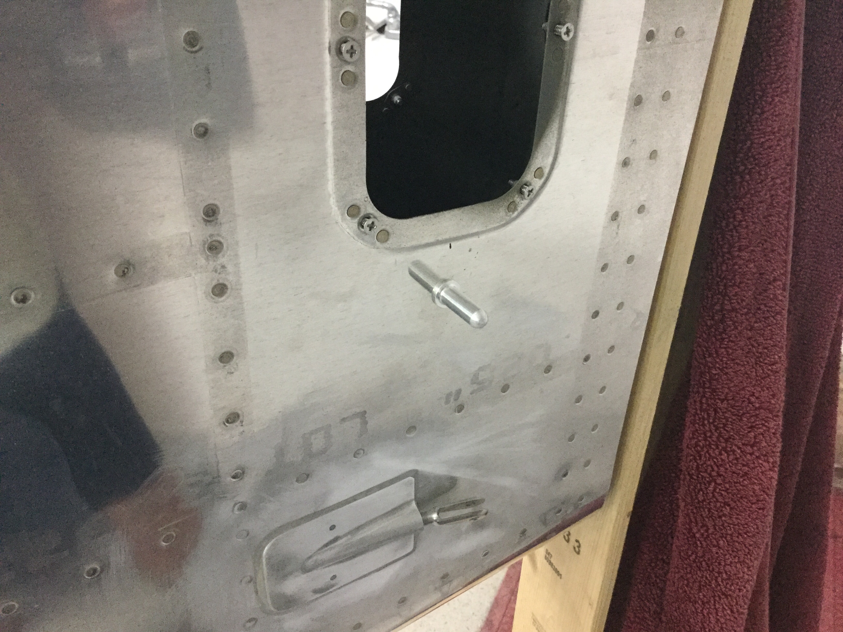
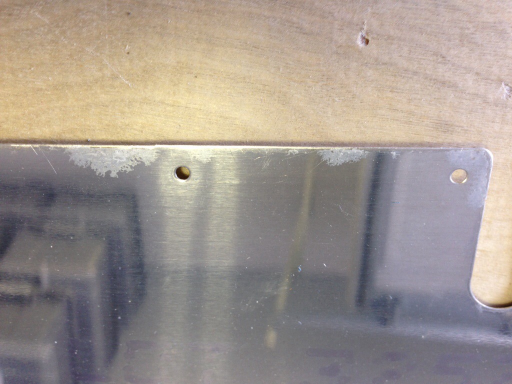
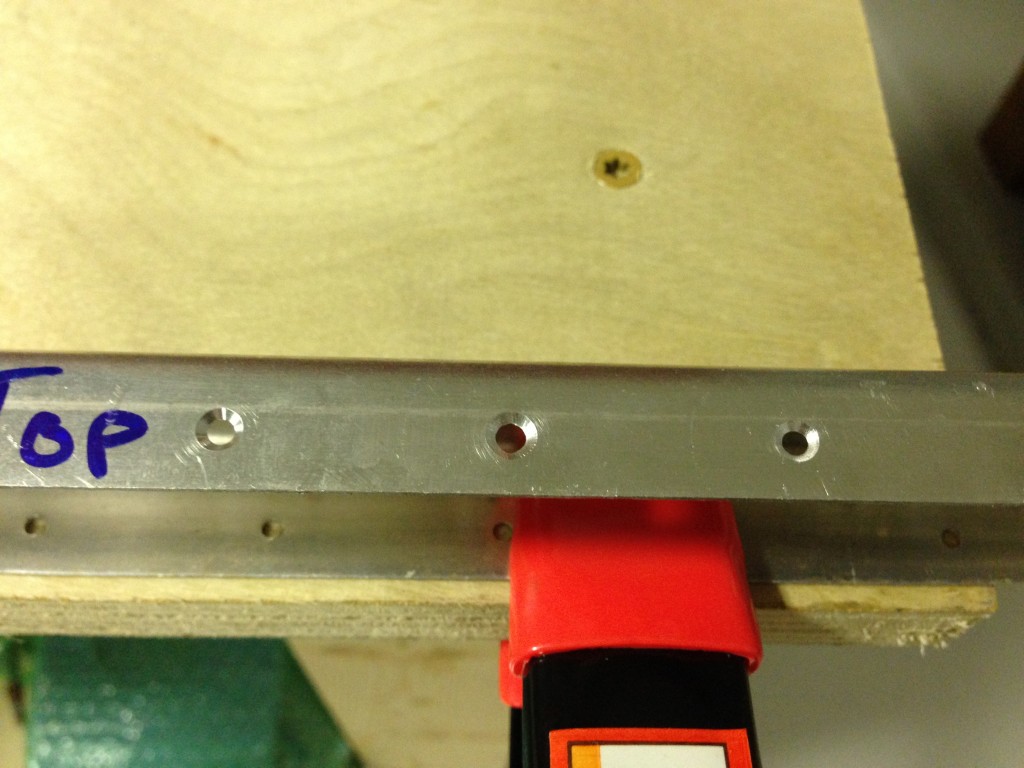
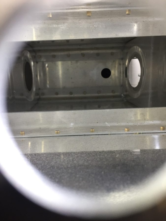
The only hiccup came when working on the elevator trim cable. The original builder had installed the plastic snap bushings the trim cables run through while building the stab. Unfortunately, he put the wrong size bushing in one of the holes that was buried in the spar. The cable wouldn’t pass through. Fortunately the hole was the correct size but man was it a pain in the ass and fingers getting that old one out of there.

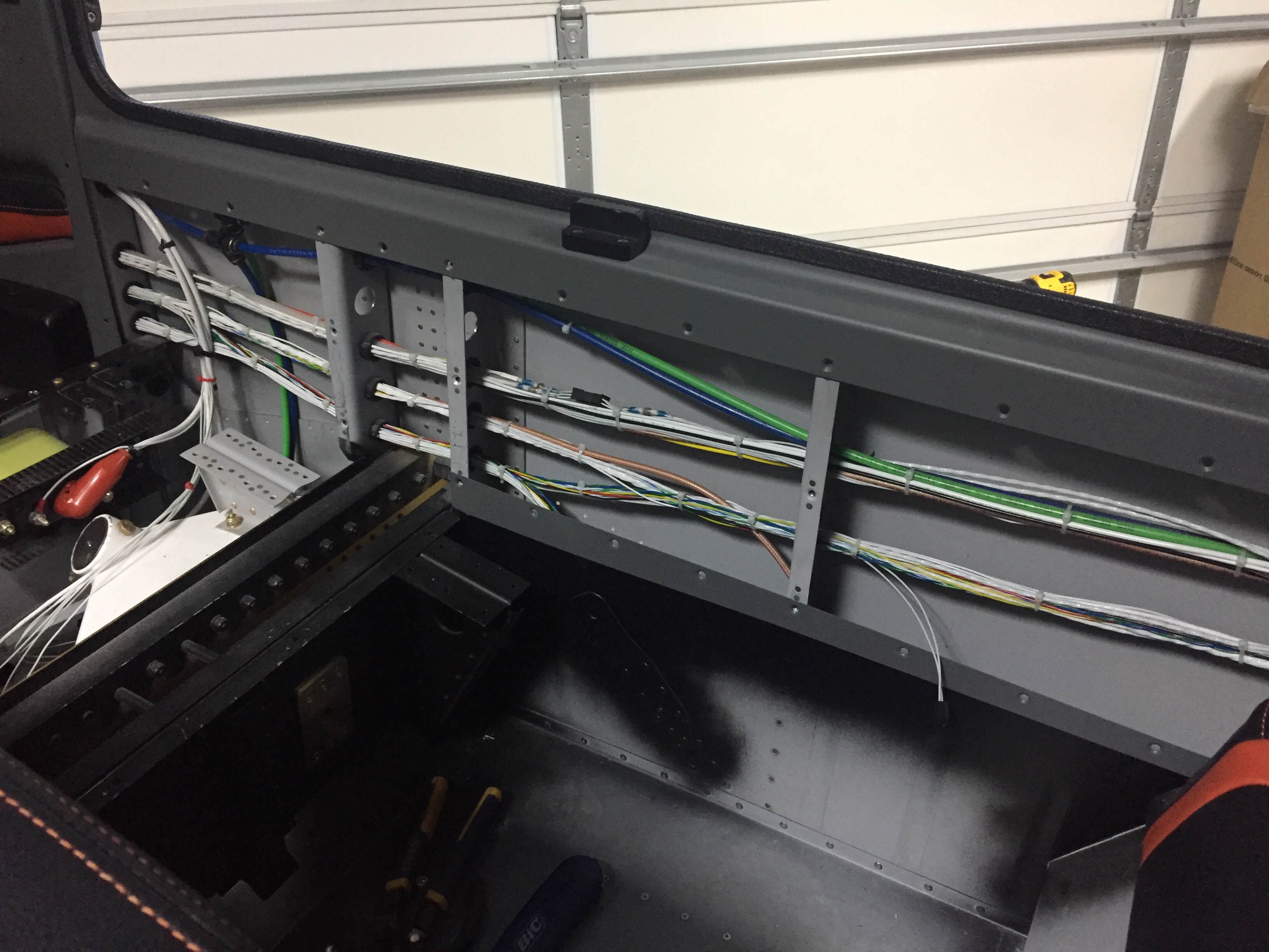
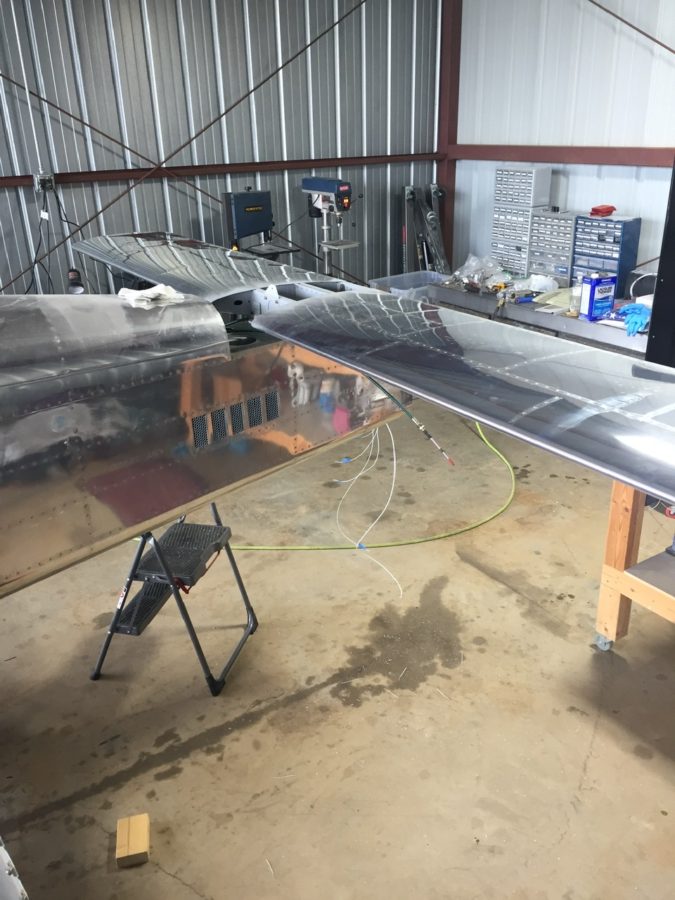
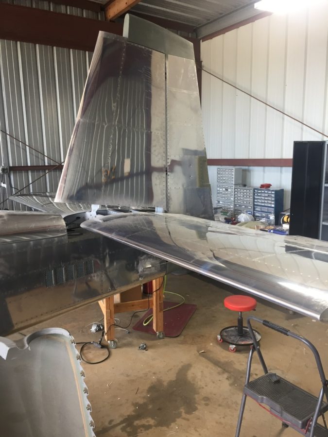
Laura helped me bolt the rudder on next to set the rudder cables up and do some trimming for the rudder trim wires and tail light wires. All easy stuff and its really exciting to see the tail feathers finally get attached.

I was able to finally hook up the elevator torque tube after drilling the horns. I was careful to get them lined up accurately and am pretty happy with the end result with the right elevator being lower on the trailing edge by about 1/16″.

I then set out to start the rigging process by centering the stick and adjusting pushrods to get the control surfaces all lined up. It takes quite a bit of stick movement to get the control range established by the plans and I found some interference with a bolt on the aileron rods under the seat pans. I was able to switch the bolt orientation and it cleared right up.

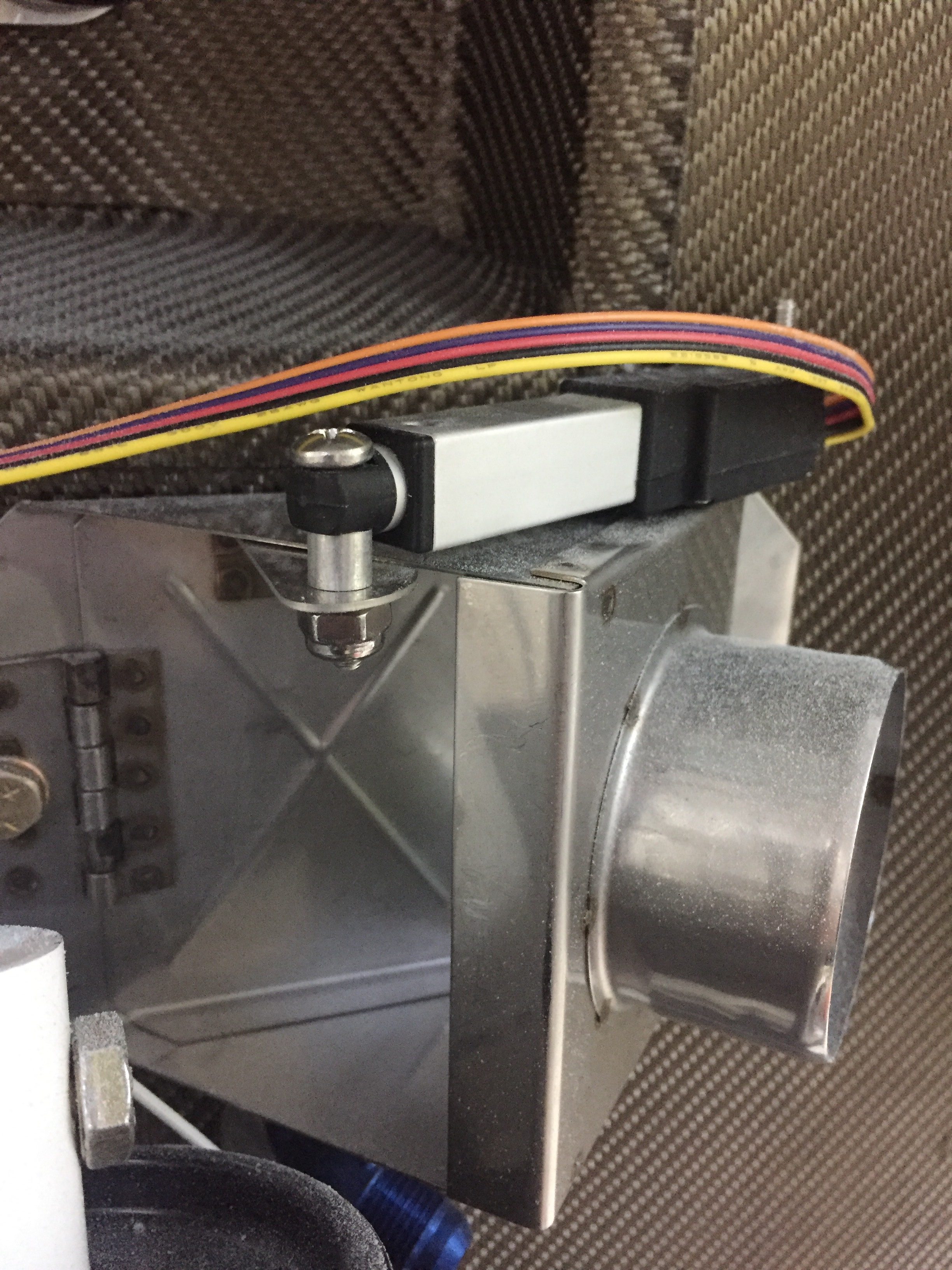
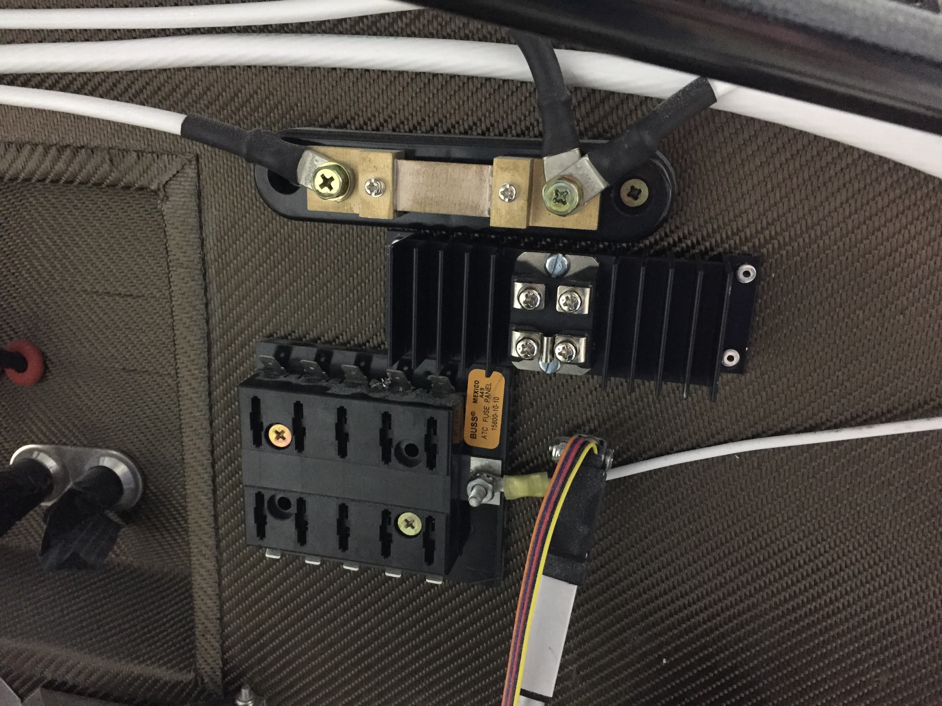
The autopilot roll servo went into the right wing pretty easily as well. I had the mount installed during wing construction, so it was a matter of bolting it in and attaching it to the aileron bell crank. The wiring hooked up quickly since I had already ran the wires and installed a connector.

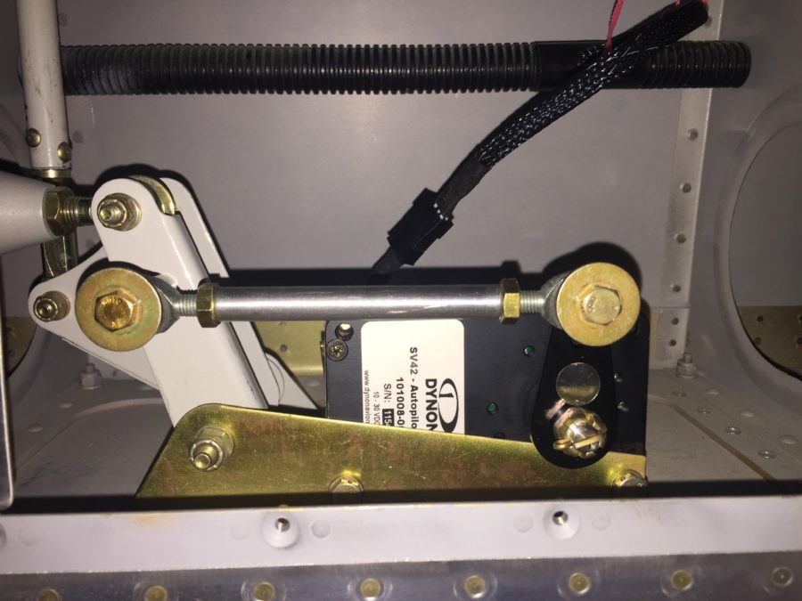
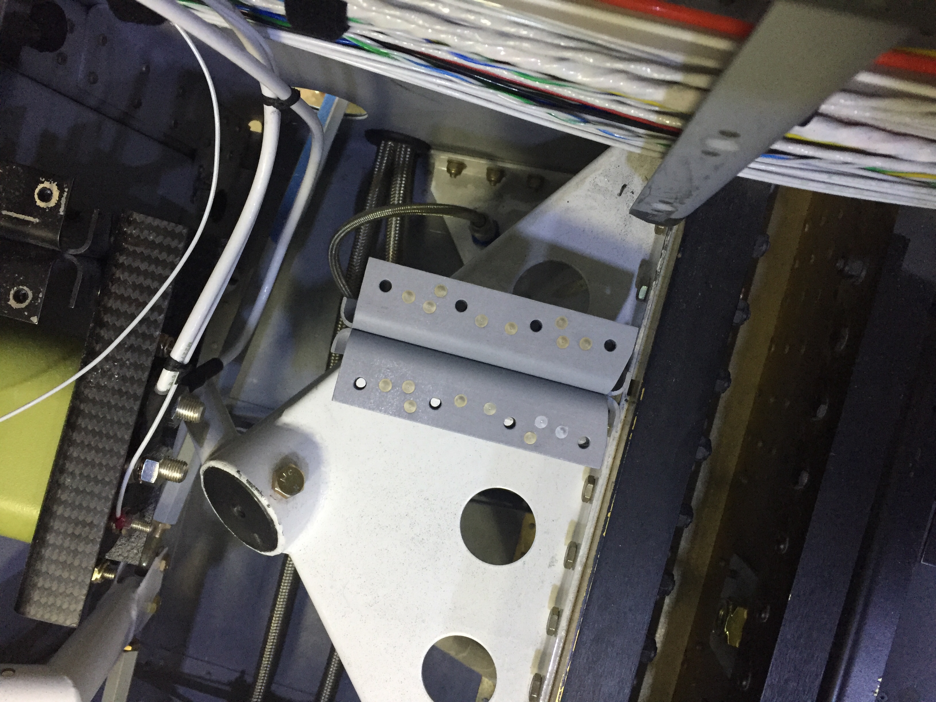
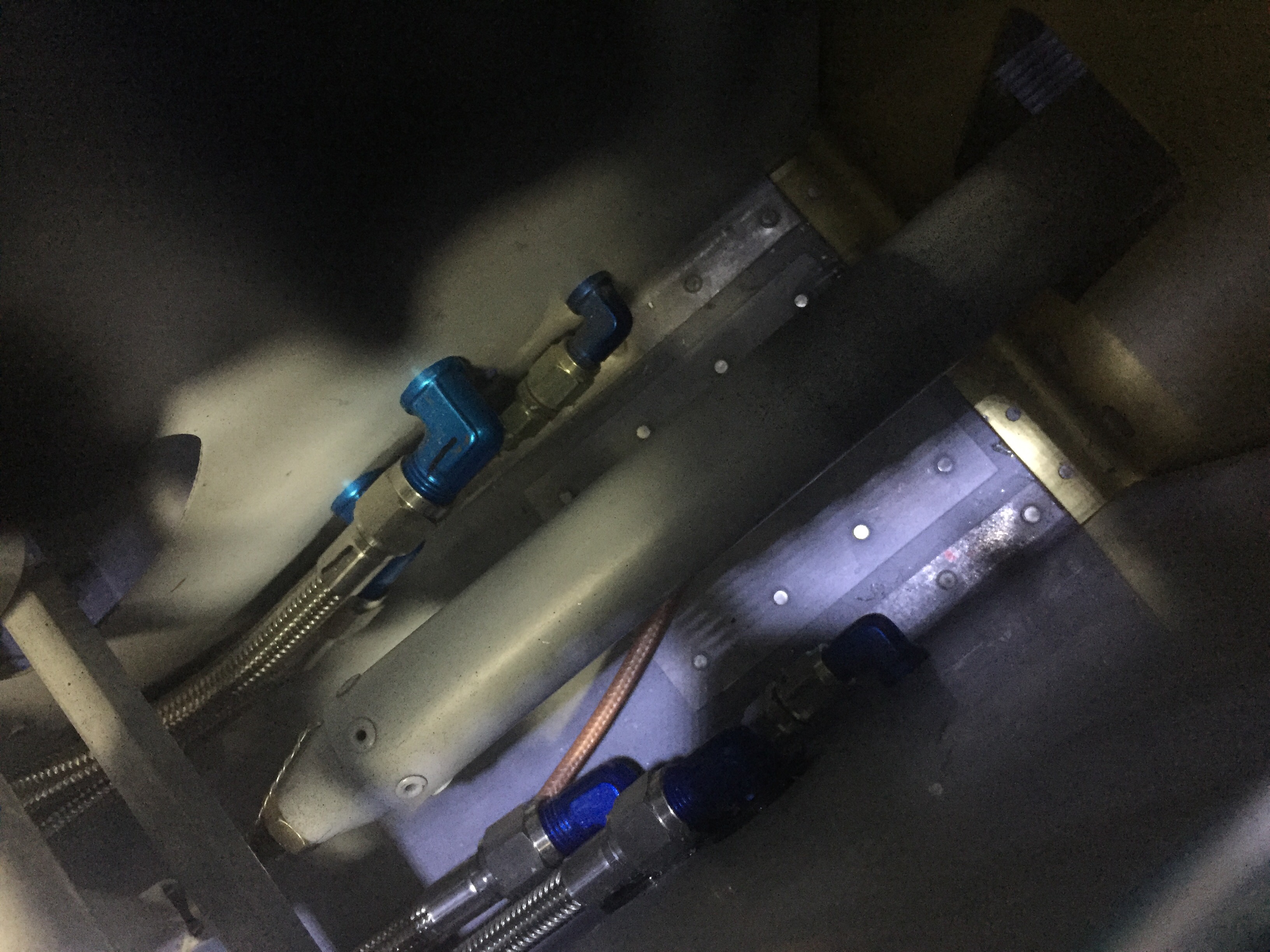
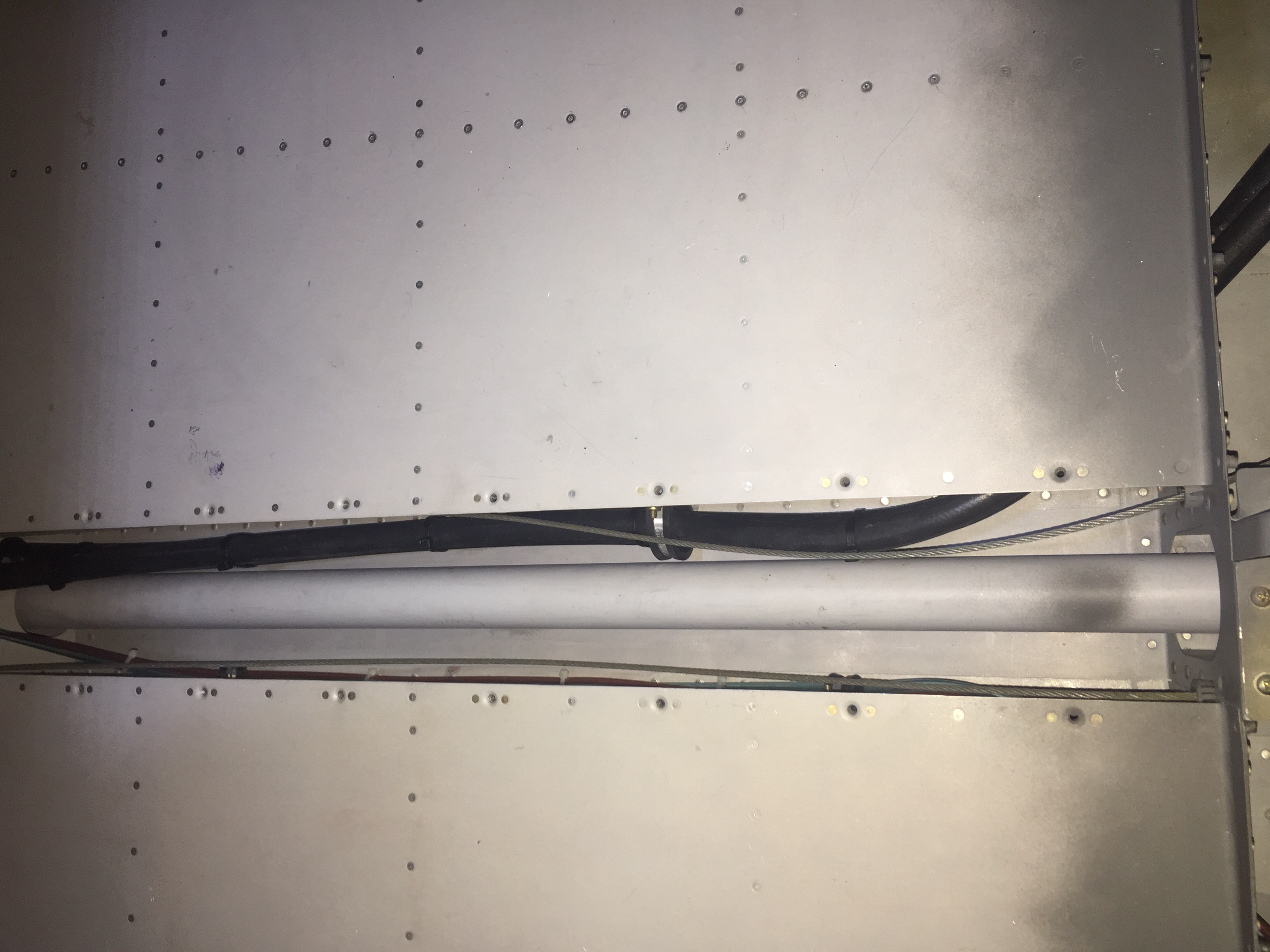
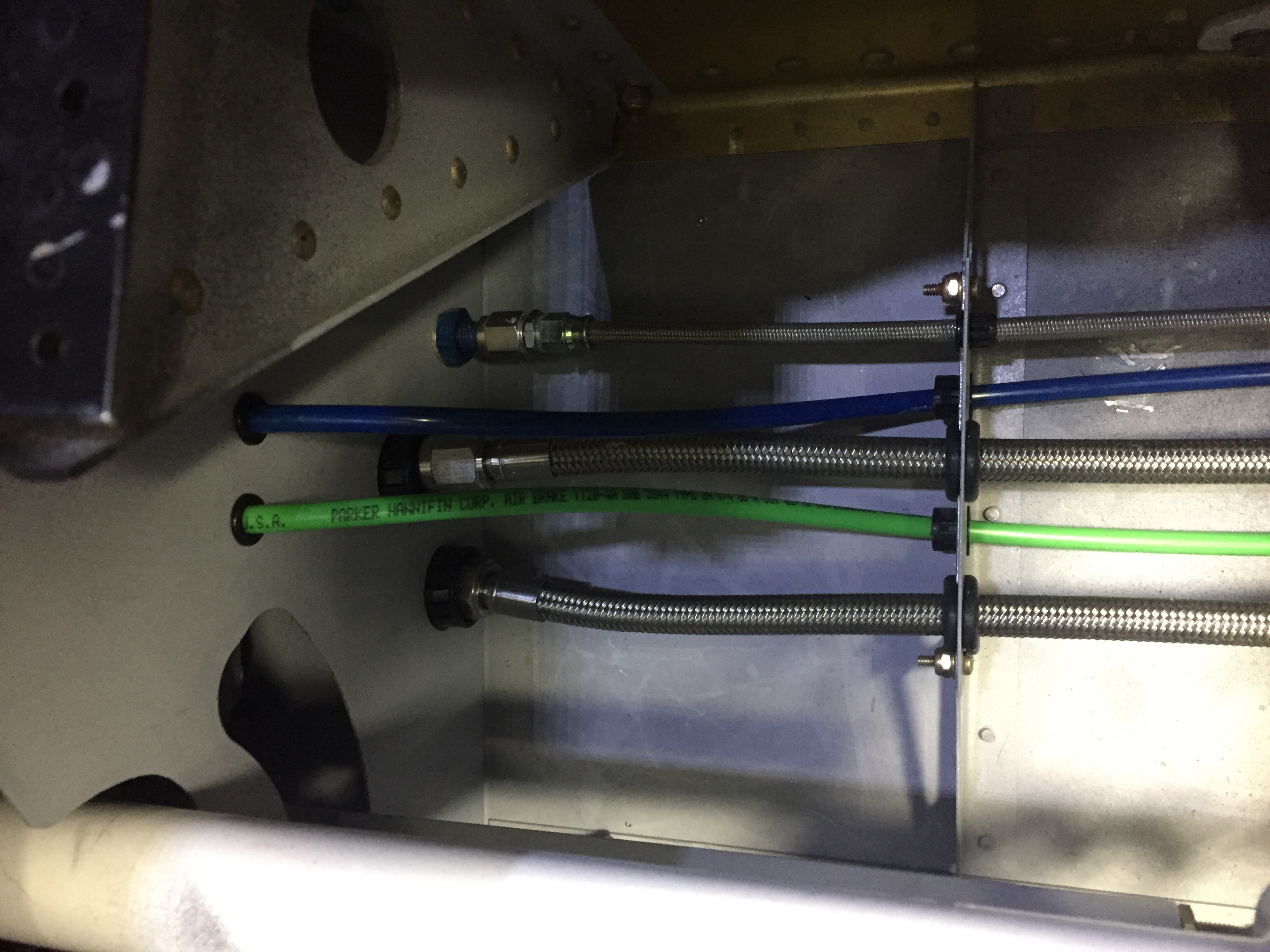
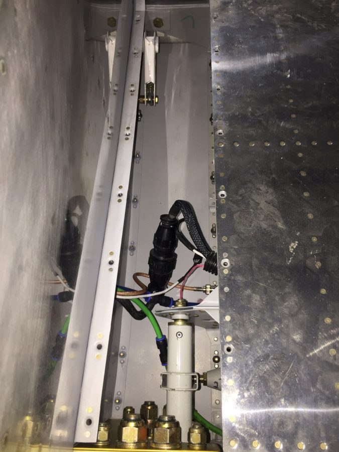
I cleaned up a bit of the wing root area as well, hooking up the CPC connectors, pitot/AOA tubing, and ensured it all cleared the control rods inside. I had planned to mount a bracket holding the CPC and pitot/AOA tubing somehow, but the whole bundle is so stiff, I’m not too concerned with securing it further. It’s also well clear of the torque tube despite the appearance in the picture.

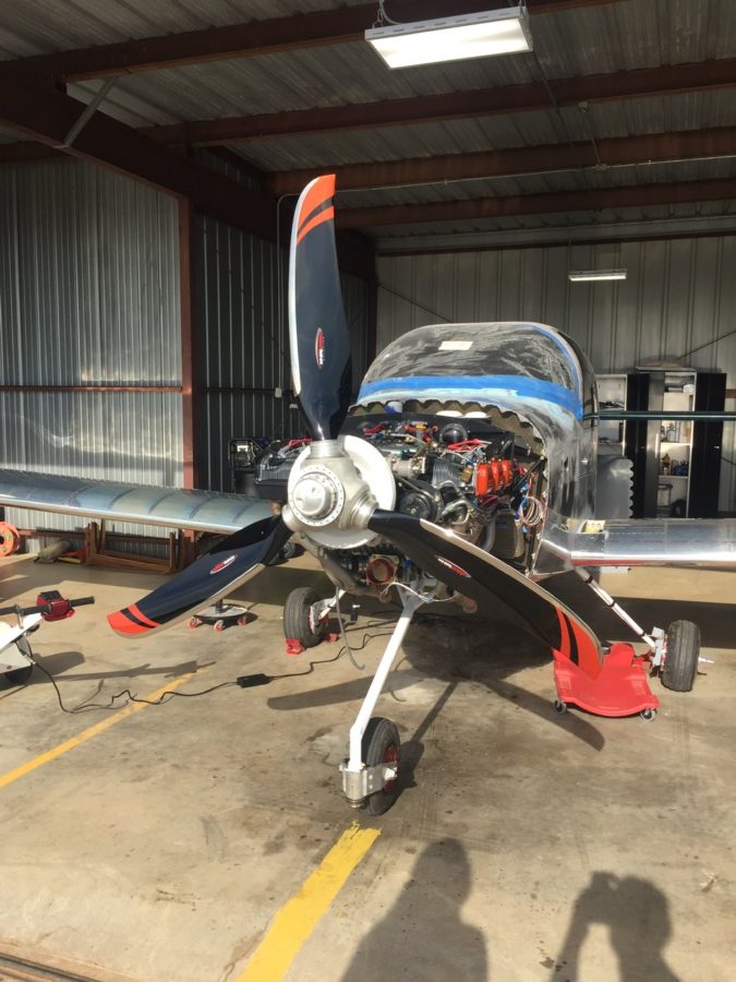
Finally, we had some good light from the sun on the propeller and I couldn’t help but drool over it for a few minutes. The orange over black with the polished leading edges are just too damn cool looking. The scimitar shape is sexy too!

Punching the punch list

There are a lot of little jobs that go along with the big jobs on building a plane.  I’m trying to use my time efficiently while waiting on the engine to knock out a bunch of them.  The first was fixing the arms and servos on the heat ducts up front.  An order to ACS and a few minutes at the band saw and the servos for the heat and oil coolers were attached properly and pots adjusted for full travel.  I also spent an hour trouble shooting a bad pot for the rear heat duct, as I have a switch that allows either the front or rear rheostats to control the servo and the rear rheostat was inop.

I cussed and bled in equal amounts installing the last of the seat rail brackets now the gears are on.  The nuts and bolts are not easy to access at this point, but you have to wait in order to install the gear bolt.  I also put in the last bolt and custom spacer for the GPU plug which helps reinforce the receptacle by attaching it to the seat pan.

I ignorantly forgot to install the transponder antenna before buttoning up the tunnel, so I had to take the center console, tunnel cover, and lower instrument panel off to get down in there.  Of course I burried it near the core of the earth which made access tricky to say the least.  I was able to squeez my hands down there and got it all bolted on with the coax attached.  I knew I had left one fuel line untorqued but couldn’t remember which one so checked all fuel line fittings for proper torque.

The last task in the rear tunnel is to secure the aircon lines which I did with some hose clamps and edge grommet material.  Again, not fun to get to the hardware but it was doable and will rarely if ever be removed.  The lines are now secure and fit nicely in the tunnel, I’m glad I didn’t run them down the side of the fuse.  I also secured the last little sections of the O2 lines in the tunnel.

My ELT antenna placement has been a topic of disagreement on VAF, as I really wanted to avoid mounting it on top of the tail cone.  It’s big, ugly, and ugly.  Mainly, though, it’s ugly.  It’s also essential to my life and the lives of my passengers should the worst happen and we have an accident, so I guess it’s important to do it right.  I debated on doing some reception tests with it mounted internal to the tail cone, but honestly, I just got lazy and decided it really isn’t that ugly.  In the end, I chose to do it the right way and put it on the top of the tail cone.  The cable was secured along a bulkhead and the last of the wiring clean up for the O2 tank / ELT was completed.

I love spending time wiggling back into the tail coffin, I mean cone, so I made a fort with blankets and towels and dove in to attach the OAT sensors to the ADAHRS and finish securing tail cone wiring.  I put the OAT sensors below the access panels underneath the horizontal stab since I had all of my wing wiring complete and for shorter wire runs to the ADAHRS.  Since they have to be calibrated anyway, I’m not too concerned with exhaust from the engine affecting them too much.

The O2 tank was put back in for good and connected to all of the lines.  I also attached the pitch auto pilot servo to the bellcrank and will connect the yaw servo once the tail feathers and rudder cables are rigged at the hangar.  That is the last task in the tail cone and can be completed without having to crawl all the way back there.  It’s going to be motivation in life to keep from getting fat or have a small child that can slide back there for maintenance, it’s a very tight fit with all the extra stuff I put back there.

More zip tie work on the side walls as I cleaned up all of the wire bundles.  I was lazy and didn’t lace them.  If you don’t like that, you go build your own damn airplane!  Lots of zip ties.  Overall I’m happy with the wire runs, I was able to keep coax with mainly data / signal wires and have the high current ones seperated.  I have seen plenty of aircraft with everything bundled together without issues, so I think it’s more important to terminate and ground properly than anything.

The pitot / AoA tubing needs to run across the fuselage from the left wing to the right sidewall, so I put two holes in the tunnel and used free holes from the fuel line anchors to run the blue and green tubing.  The wing is already plumbed, so these lines will connect with those from the wing with two connectors and be done.

Finally, I put the 30 amp Schottky diode on the firewall between the shunt and engine fuse block.  I had this in my electrical design but just in the wrong location.  It provides redundant power input to the engine fuse block only, keeping it from backfeeding the rest of the electrical system.  The power comes in from the emergency engine power switch which comes from the battery to the fuse block.  Big picture, it is a redundancy for the single point of failure of the master contactor or short in the system.  A complete electrical failure or engine stopping SOP will be to turn off the master switch (leaving PFD, MFD, and G5 operating on independent back up batteries) and switch on the emergency engine power switch.  If the battery has any juice at all, it will go only to the engine fuse block.

Service Bulletins

While having some down time at home that I can’t do much productive anything with, I decided to research quite a few things while lying in bed after surgery.  One of those was service bulletins.  There are a handful out there for the RV-10 and are a lot like AD’s issued by the FAA, but they are not mandatory by law.  Highly recommended, however, so in the home built world, you comply with them.  With this being a build log, I wanted to document them here and then I’ll make the associated entries in the air frame log book once I have one.

The empenage kit (oldest original kit) was delivered in October 2005 to the original builder, thus I have only addressed those SB’s relating to the dates affecting our kits.

SB 06-2-3 is for the vertical stabilizer rudder mount.  This SB was completed by the original builder and complies with all aspects of the SB.  I could not get a good picture inside a tiny access hole, however, visually confirmed the doubler plate is in place inside the main spar of the VS.

SB 06-9-20 is for the trim cable anchor nut on the elevators.  While our kit does have the double welded nut, I chose to upgrade to the CNC machined piece by IFLYRV10.com.

SB 08-6-1 is for the F-1010 bulkhead near the vertical stabilizer in the tail cone.  My kit came with the SB contents and I completed it as part of the original build of the tail cone.

SB 16-03-28 is for the aileron hinge brackets possibly cracking on the inboard aileron mount.  I have removed the portion of the gap fairing to allow future inspection and no further action is needed until flying, at which time an annual inspection of the bracket must be made and noted in the log.

There are other SB’s that will affect our build, however, I have not gotten to that stage of the build yet, so will cover it in another post.

I don’t like that color

I have had enough sanding for a while and figure it’s time to throw some primer on top and see what the results are on the control surface tips.  I was pleasantly surprised how good they turned out.  The sanding really paid off and with the few pinhole exceptions, the transitions between the fiber and the aluminum are very smooth.  The primer is an ugly color, but at least it highlights where you still need work.
IMG_1010.JPG
I was especially excited about the top of the rudder where I had to add a lot of fill to make it nice and smooth.  The micro added to the West Epoxy is solid as a rock when cured but still sanded pretty easy.  Really easy to work with.
IMG_1011.JPG
So the elevators are complete now and went back up on the wall.  I have just the bottom rudder fairing joint to smooth out and then I’ll start on the rudder trim.

Creamy peanut butter

After the epoxy set up on the fiberglass tips, it was time to put on the filler, often referred to as micro, to smooth things out.  I’m using the West epoxy system and the 407 filler.  It’s an extremely fine powder that is a tan color and according to others very easy to work with.  You mix up the epoxy as normal with a 5:1 ratio and then add in the filler to get a consistency of creamy peanut butter.  Then just spread it on and smooth it out as best you can then wait for it to cure.

I’m not a stranger to using Bondo, dry wall mud, and other fillers, but I still have a few lessons learned from my first experience on the plane.  First is when mixing the filler, you want a really think peanut butter mix, not creamy.  My first batch ran and settled a little too much, requring me to position the pieces so it wouldn’t drip.  Keep in mind it takes a few hours for the slow hardener to set up.  If you have a lot to add to build up, make it as dry as you can.  Second, follow Ron Propeil’s advice and set it and forget it.  Just like dryway, the more you mess with it, the worse it gets.  You won’t get a perfectly smooth application so stop trying.  That’s what sand paper is for!  Third, is patience which I do actually have for this.  One coat is seldom enough to smooth out whatever your working on.  Go in stages and don’t try to build Rome in a day.

Thus, my first coat was pretty successful.  I scuffed up the newly laid fiber and made sure the aluminum was scuffed with a Scotchbrite pad.  Then clean everything with thinner and apply the filler.  I filled in a lot on the tips’ leading edge where it didn’t match up with the aluminum well.  I was also excited that it actually set up well!  I have a fear of mixing the epoxy wrong and it just being a goopy mess.  The pump system for the West epoxy is a must have.

20140723-163616-59776751.jpg20140723-163615-59775937.jpg

Next, you get to break out the sand paper.  And a lot of it.  A couple lessons on this too. Have a variety of grits; I used 80 to knock off the big ridges and bumps, then 150 to contour, and 220 to smooth it all out.  I found that the 150 really didn’t work too well as the dust would bond to the paper and clog it up.  The 220 worked great and lasted a long time.  I have a couple of different blocks that are working well.  I’ve read never to use your fingers since they will not sand uniformly, but there are always a few spots that the block can’t get.  Make sure not to sand too much off.  It’s better to get it close and put another thin layer of filler on to really smooth it out.

I put the second coat on a bit dryer than the first and that was good for the big spots, but also harder to get a smooth application.  For the finish coat, it’s better to have it a bit creamier so it will apply smoothly with no pinholes.  The second coat was sanded with 80 and then 220.  You can tell if you have low spots by the different color when sanding which is nice.  Never sand out a low spot.  Add to it then smooth it out.  Blow off the dust, clean with thinner, and repeat the application process.  This is the third coat and I’m pretty sure it will be enough.  The corners are still hard so I gooped it on and will sand it smooth.  I’m hoping the other side will go faster since I’ve got some experience under my belt.  I’ll finish it all with a 440 grit before doing some quick primer and reevaluating.

20140723-163618-59778462.jpg20140723-163617-59777588.jpg20140723-163621-59781023.jpg

And of course, you have to have things organized.  So to keep all this sand paper (I have more than listed), I got a cheap expanding folio at Wal-Mart Aviation Supply and threw some labels on it.  This works perfect and keeps it all in one spot.

20140723-163619-59779322.jpg20140723-163620-59780179.jpg

Here’s a tip for you.

Fiberglass is very daunting to some while no big deal to others.  I’m in the middle.  I don’t like sanding for ever, but it’s a nice change from deburring.  The tips of the control surfaces and both wings and stabilizers all are made of fiberglass and get riveted onto the aluminum.  While the plans call for that the to the end of it, some builders will put a layer of glass over the joint to seal the gap, improve aerodynamics, and improve the look.  Since I have plenty of time, I decided to do the same.

First step is to test fit the pieces and notch out around the trailing edge.  I also needed to cut a bit off the flange so it would fit flush under the skin.  Overall, these are formed pretty terribly next to the aluminum but they are old and I’ve heard Van’s molds are better now in newer kits.

20140717-163106-59466163.jpg

After fitting, I drilled and countersunk the fiberglass while dimpling the aluminum to take the pop rivets.  This was pretty straight forward and the only exception I will make is to put nut plates and screws on the bottom rudder fairing so I can access the nav light.

20140717-163105-59465736.jpg

The first step in glass thing joints is scuff the area with 80 grit sand paper so the resin has a bit more bite surface to it.  I then mixed up the West Epoxy system with the slow hardener and painted on a thin coat.  I used a 1″ glass strip cut to size and laid it on the wet epoxy.  Others have done more than one layer, but I plan on sticking with just one.  Make sure that all the fabric gets soaked and minimize the excess then just let it sit.  I did apply a bigger piece on the leading edge of the rudder tip since it was formed shorter than the aluminum structures.  I’ll layer one or two more times to build up the difference then fill this with micro and create a nice smooth surface.

20140717-163106-59466983.jpg

The trailing edge cut required a bit of sanding down to match the profile of the elevator.  I used my belt sander which worked really well as long as I was careful to watch the shape and amount taken off.

20140717-163106-59466572.jpg

This is the final result of the first glass laid on the project.  I’m pretty happy with it.  Next step will be some sanding and then a layer of micro to smooth it all out.  Sand and repeat, I’m sure.

20140717-163107-59467415.jpg

First Inspection

The project got it’s first inspection today when the local EAA Tech Counselor, Dale Ensing, dropped by to take a look at my work. I wanted him to critique my build early on to ensure that I was on the right path and correct any bad habits before getting too far into the project.

As typical, the visit turned into swapping stories and sharing experiences, all of which something can be learned from. People like him make this rewarding project even more fun. He took a good look at the work done thus far by the previous builder and by myself with favorable comments. The main recommendation he had for me was to go ahead and spot prime the outer skins on areas where I had taken of the surface corrosion. I asked him several questions about priming, rivets, other random build techniques and got some great info and tips from him. Best of all, it was an evening spent talking about our passions for aviation!

With a boost of confidence and a confirmation of satisfactory work, I’m left with a pile of parts once again after disassembling the tail cone. I began stripping the blue film off pieces and will work now on deburring and dimpling. That will all have to wait at least a week, however, as I’m headed up to Greensboro for a week of flying and hopefully my commercial rating!

20140117-215050.jpg

Sorry, these elevators are closed

The project sat idle for some weeks I am sad to say. However, I’m not in a huge hurry and refuse to stress about this fun project so we press on.

I got back to work on the elevators and made some fast progress. With back riveting now in my “can do” bucket of skills, these smoothly went together with a lot of pop rivets on the ribs to form the internal structure. I even got my wife out in the garage to help assemble the skins and squeeze some rivets on the spar. It’s true when they say you spend weeks prepping and only minutes riveting. It was somewhat of a non-event to actually rivet!

Along the way I’ve been cleaning up what I am pretty sure is surface corrosion. It’s only on the edges and mainly where the blue film had been pulled away or bubbled up. This kit is about 7 years old and sat in a basement, so not overly surprised. I’ve been sanding it out with a 3M disc and then spot priming those areas. I also discovered a 1/8″ tear in the skin between the edge and a punched hole. After getting some advice from VAF, I decided to cut and grind it away and will fill in the void with epoxy when installing the tips.


Rolling the leading edges wasn’t terrible, but I’ll be sure to pre roll the skins next time before assembly, as others have suggested and I forgot to do.

Finally, I pulled the already made trim tabs out of the bubble wrap and fabricated the hinges for them. It was pretty straight forward and the end result was very nice. Something to be proud of.

My lessons learned thus far are: leave the blue film on for protecting from surface scratches, pre roll the leading edges, and not let as much time go by without working on it!

I can see your ribs

It’s fun when you start to make structural progress!  Tonight, I began attaching the small misc. brackets to the main spars for the elevators and also started on the ribs.  I first modified one of my workbenches to hold my back-riveting plate flush with the table (check out the Workbench page for details) to make back riveting a bit easier.  I’m very happy with the results and got the idea from the previous kit owner who had a large workbench with the same modification.

Half the ribs are attached to the skins then they are brought together once the skins are on the spars.  I cleaned the pieces well with lacquer thinner and did a final inspection on all pieces for corrosion, as I had just a few small spots on the spars and skins.  I spot primed one trim access plate but all else were fine.

Pulled out another supply for the first time, the back riveting head for my rivet gun along with rivet tape.  I really like the back riveting, it’s even better than squeezing!  I’m really dialing in my air pressure and have found that 55-60 works perfect for a nice firm hit and consistent result to match the rivet size guides.  I also quickly discovered that one piece of rivet tape can be used multiple times, so no reason to go through an entire roll on one skin.

Once the ribs are on the bottom skin, the rear spar is attached to the ribs and later the skins.  It was a bit tricky still trying to figure out the die head combination needed to get at all the rivets, but everything went smoothly and I only drilled out one flush rivet the whole evening!

Spent some time working on the website as well to update the garage, tools, and links page.  The website is almost more work than the airplane!

I love your dimples….

Good thing too, because this project has a lot of them!  I finished deburring and dimpling the right elevator skin.  Deburring takes forever it seems and is made more difficult with the shiny skin.  I can see why folks leave the film on as long as possible (for scratch resistance as well).  I also buffed out a couple of spots of surface corrosion I had on the skins and a few scratches on the spars.  I’m using the Dupli-color self etching primer to spot prime those spots.  Without going off on a tangent, I’ve researched and read on priming til I’m cross eyed and I am choosing not to prime unless specified by the plans or a condition such as imperfections in the metal.

I ensured all the ribs are labeled and disassembled everything to prepare for riveting next.  The spar needed to be countersunk on certain holes to allow a flat surface for the trim hinge to mount, so I got to use a tool for the first time!  The countersink bit is really neat, but I expericenced some chatter on it so I may need to play with the speed, as it didn’t clean metal chips away quickly at 90 PSI.

 Finally, I picked up some inexpensive L brackets for shelving from Lowe’s and mounted them above my workbench to store the HS on.  It has been sitting on the floor and my lovely wife has been very vigilant to ensure nothing hits them as she parks about a foot and a half away every night!  Now they are safe and secure and most importantly out of the way until needed down the road.

I also organized the pegboard a bit more than pictured, hung up the parts bins and just straightened up the work space.  I’m finding it even more critical to keep the garage clean and tools in their places so I can work efficiently!