Hold the door, Hodor

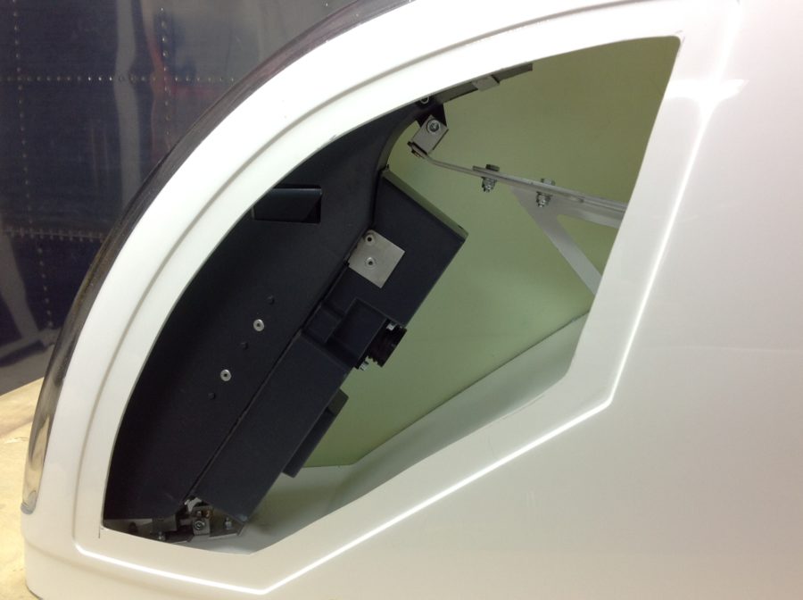
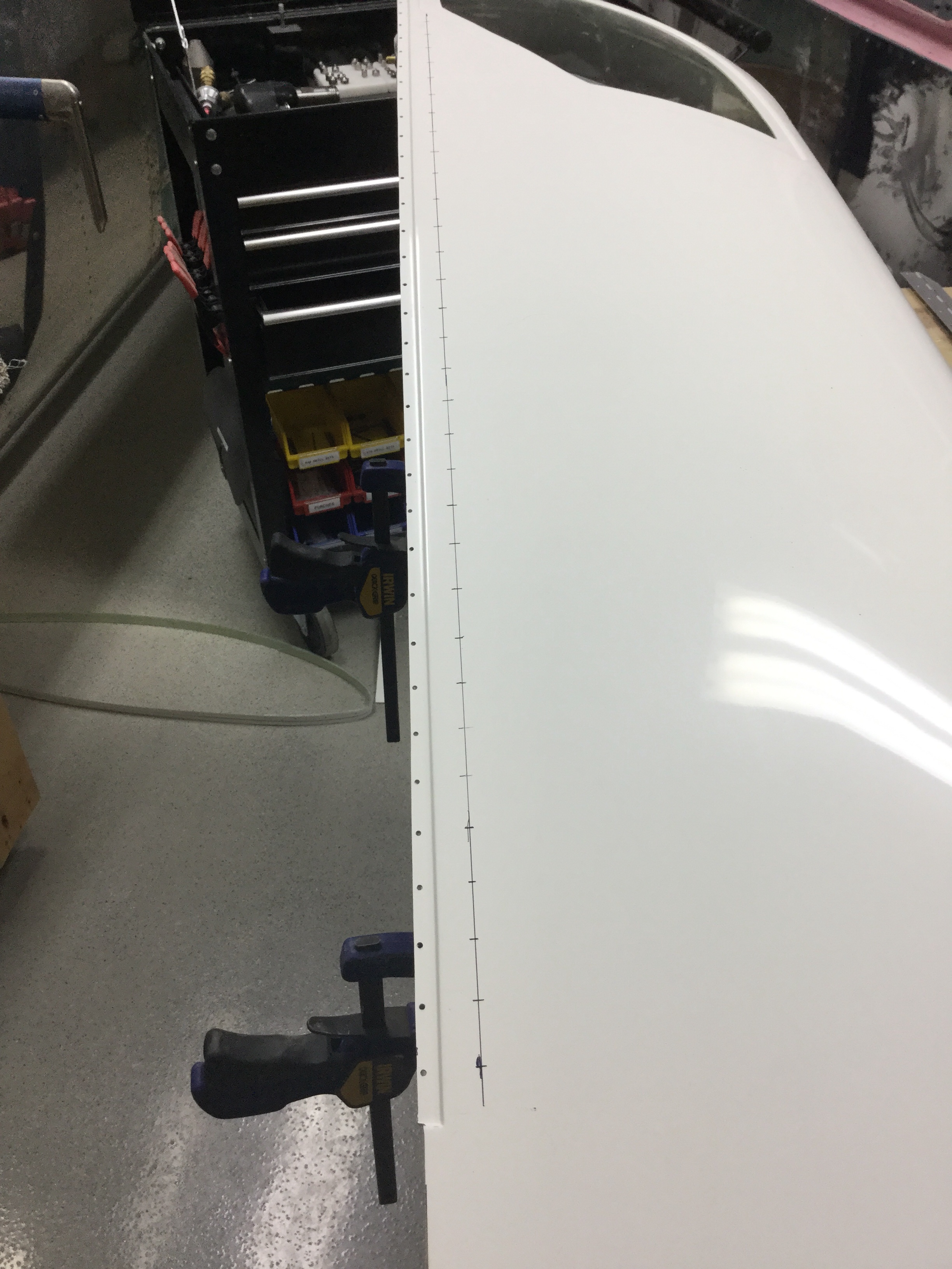
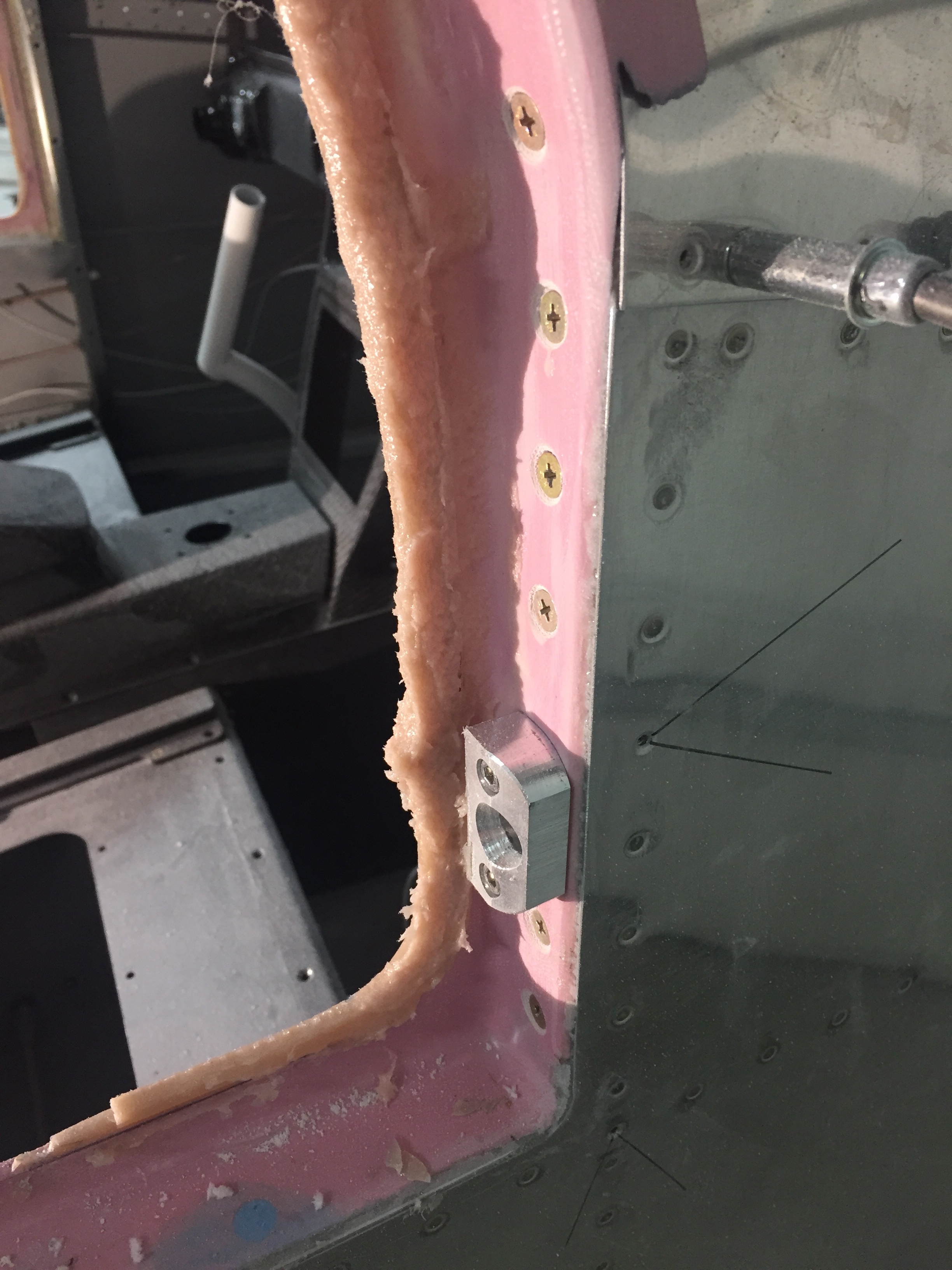
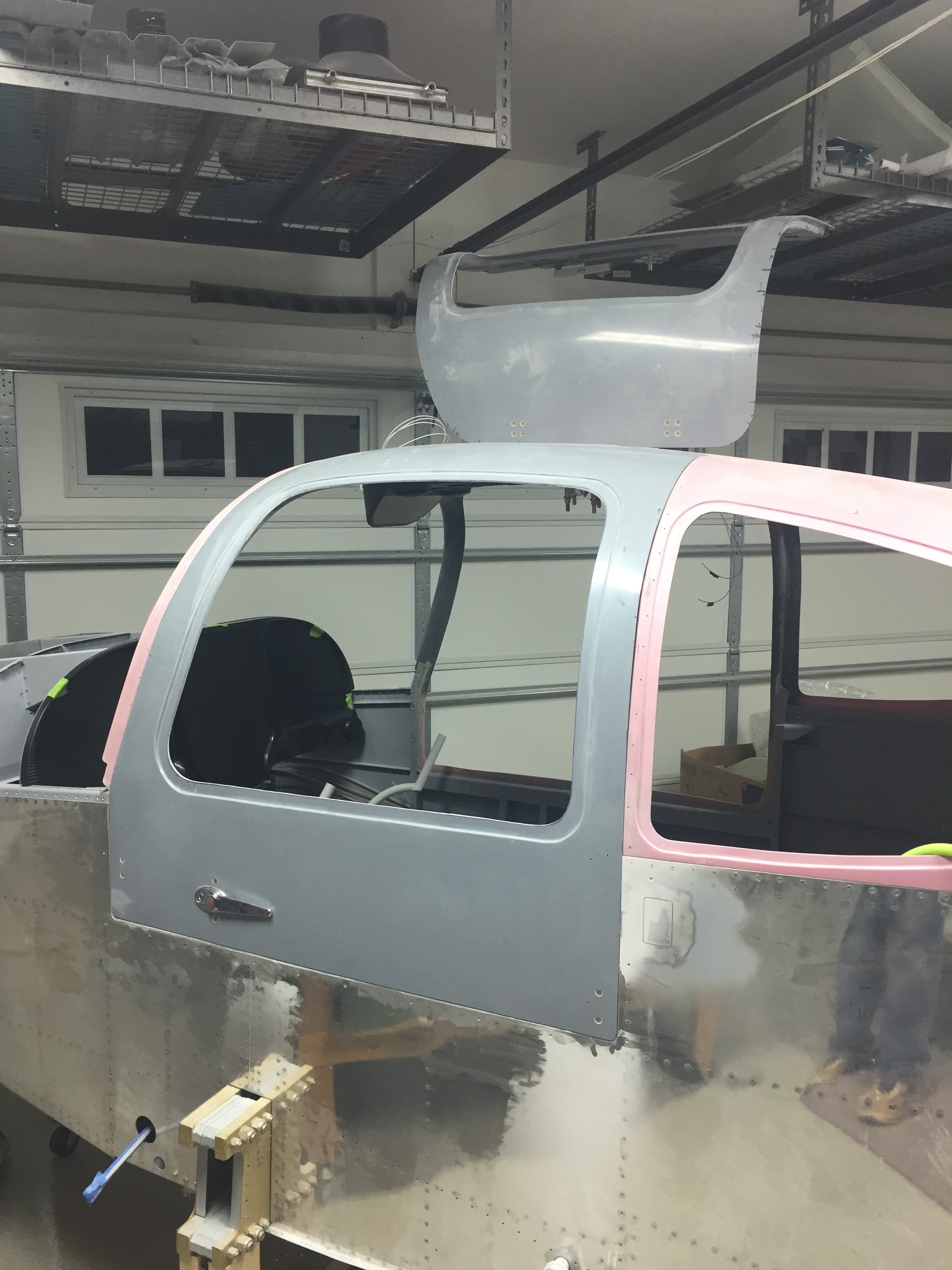
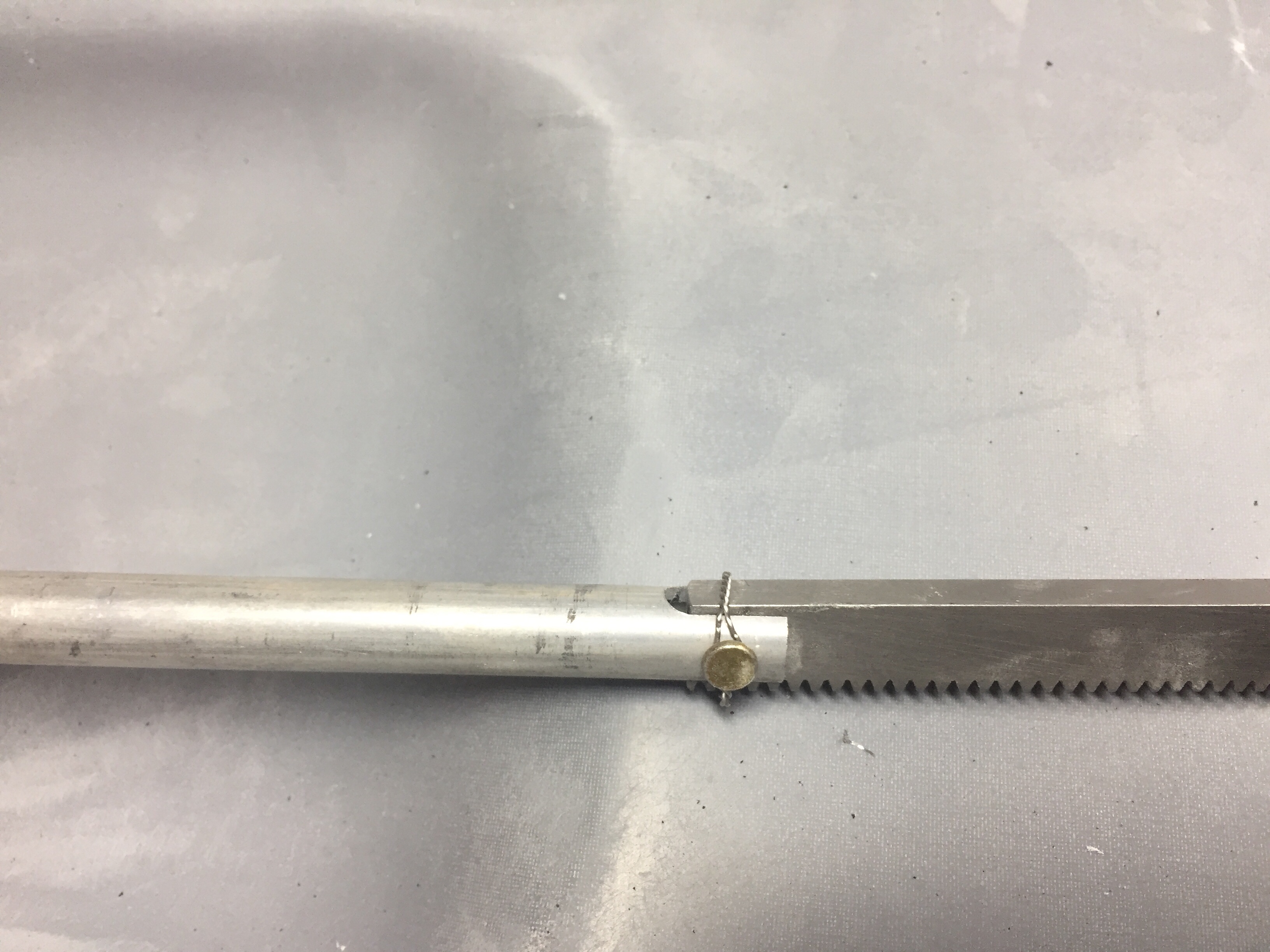
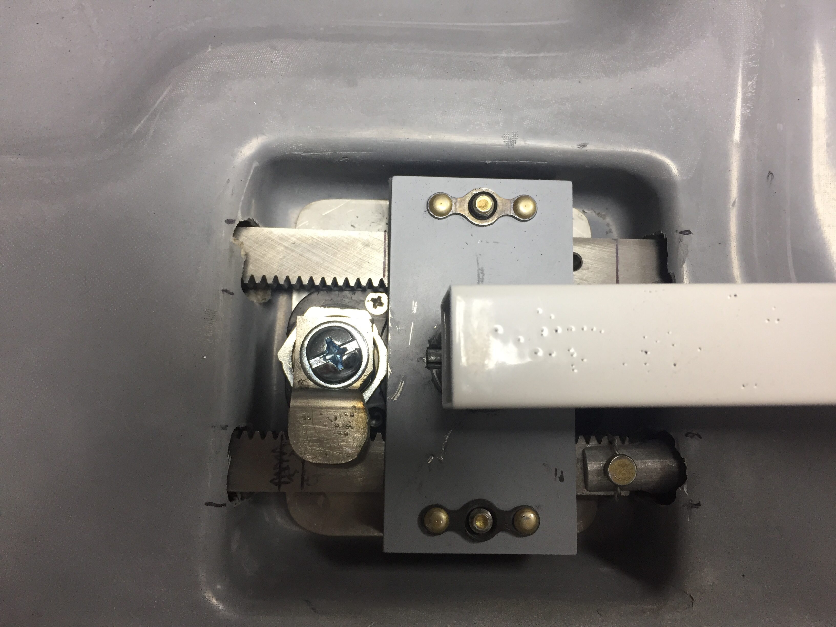
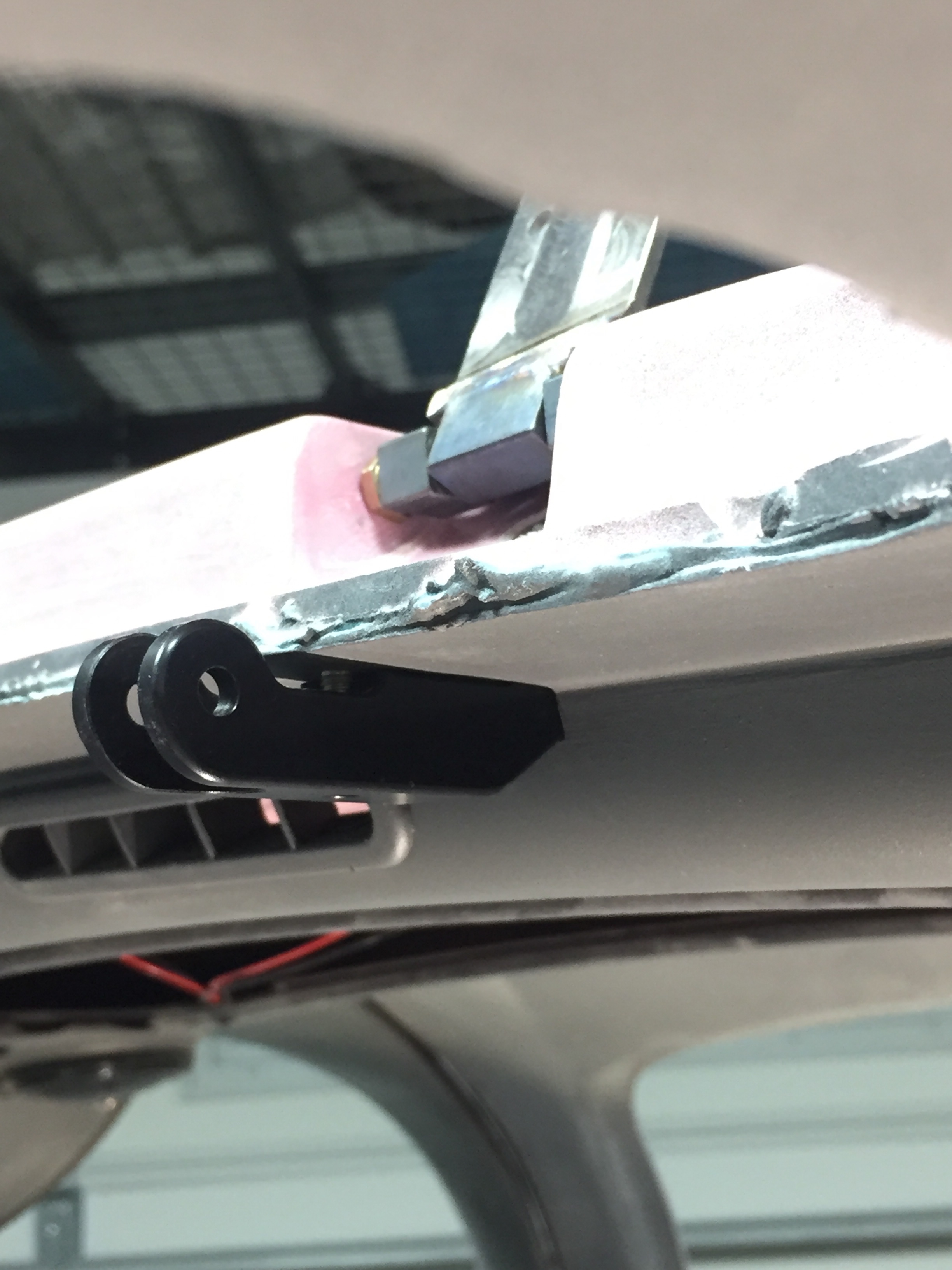
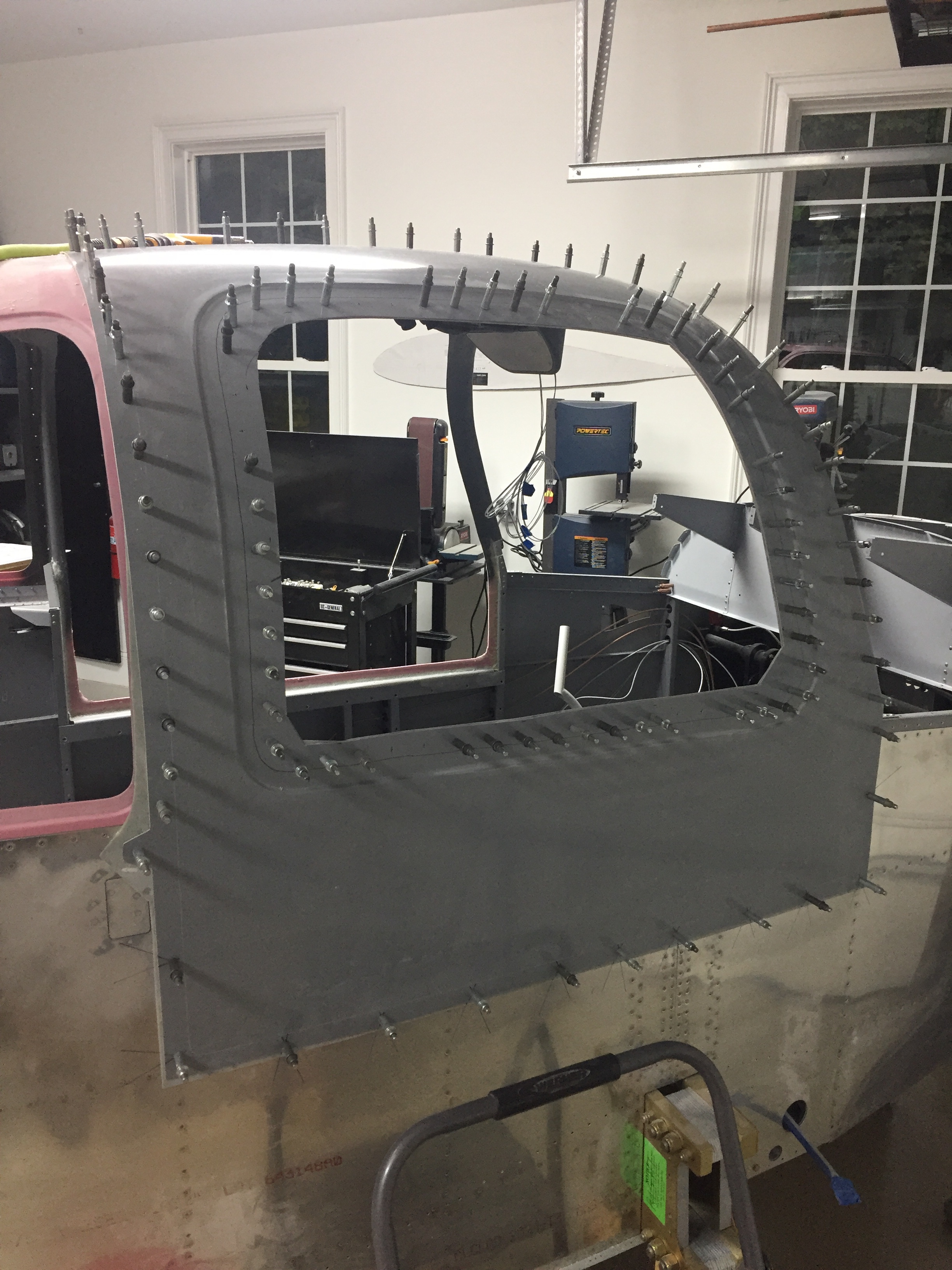
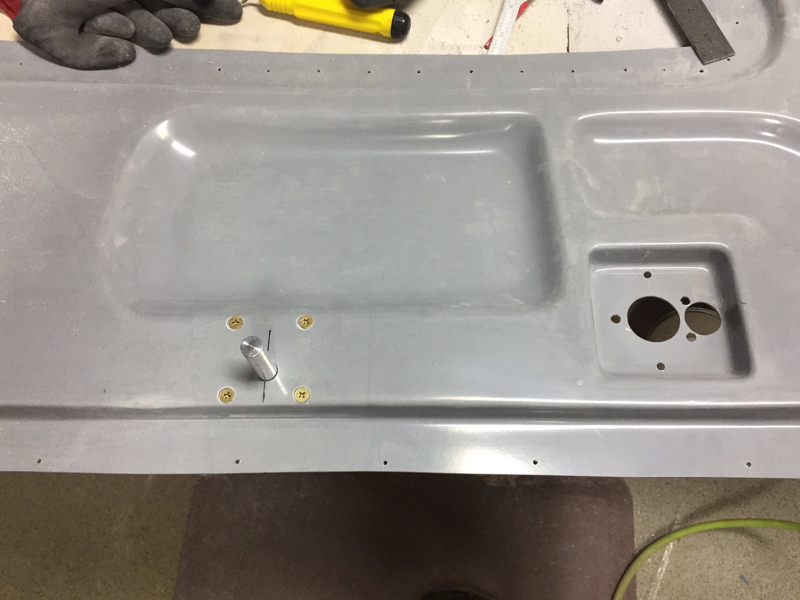
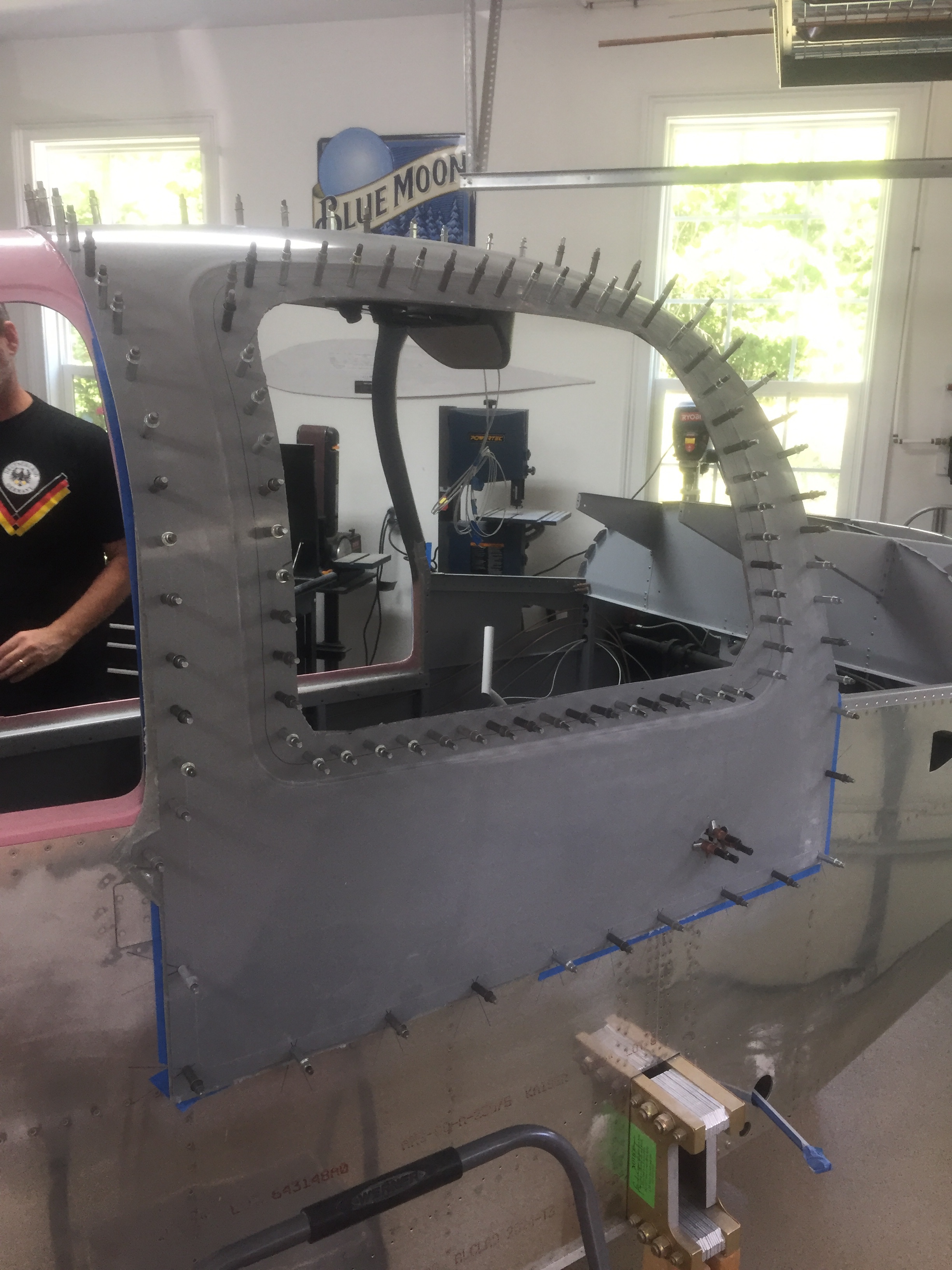
Any big cut or drilling job comes with some anxiety and the door pin hole is no exception.  Now that the door handles and pins are all installed and working like a fine oiled machine, they need a home to rest in.  I removed the magnetic tipped pin inserts and used two ground down bolts threaded into the rods to locate the exact spot to drill into the door frame and fuselage bulkheads.   This worked really well as I was able to position the door flush with the fuselage and locate the drill placement without worrying about future misalignments.
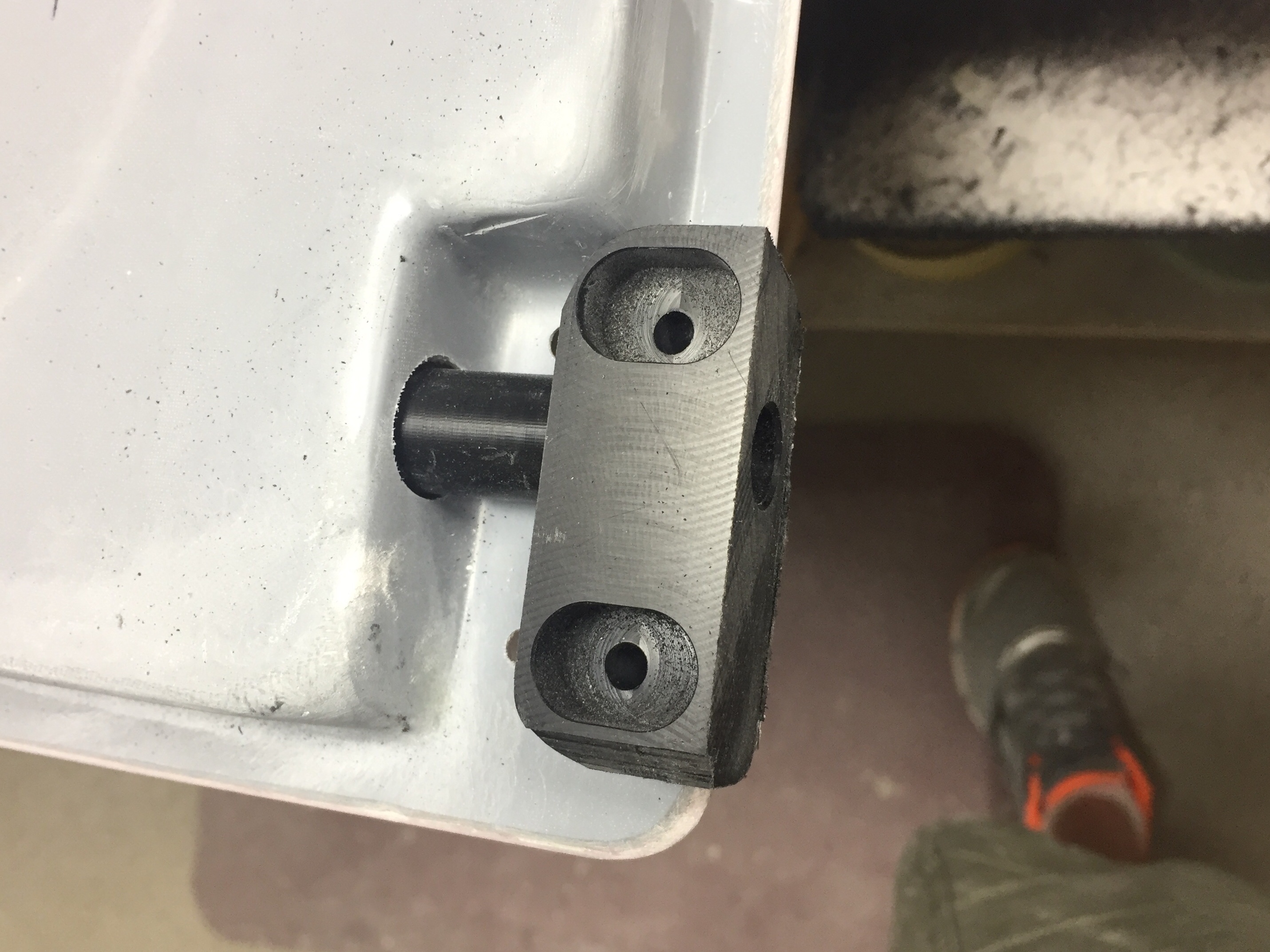
I have some fancy aluminum pin guide/blocks from IFlyRV10 that go along with the magnetic pin inserts.  These help guide the pins in and just make closing the door that much easier and smoother in coordination with the PlaneAround center cam.  I polished the holes with some light sandpaper to get a smooth action and am really stoked to say all four holes are in the perfect position the first time!
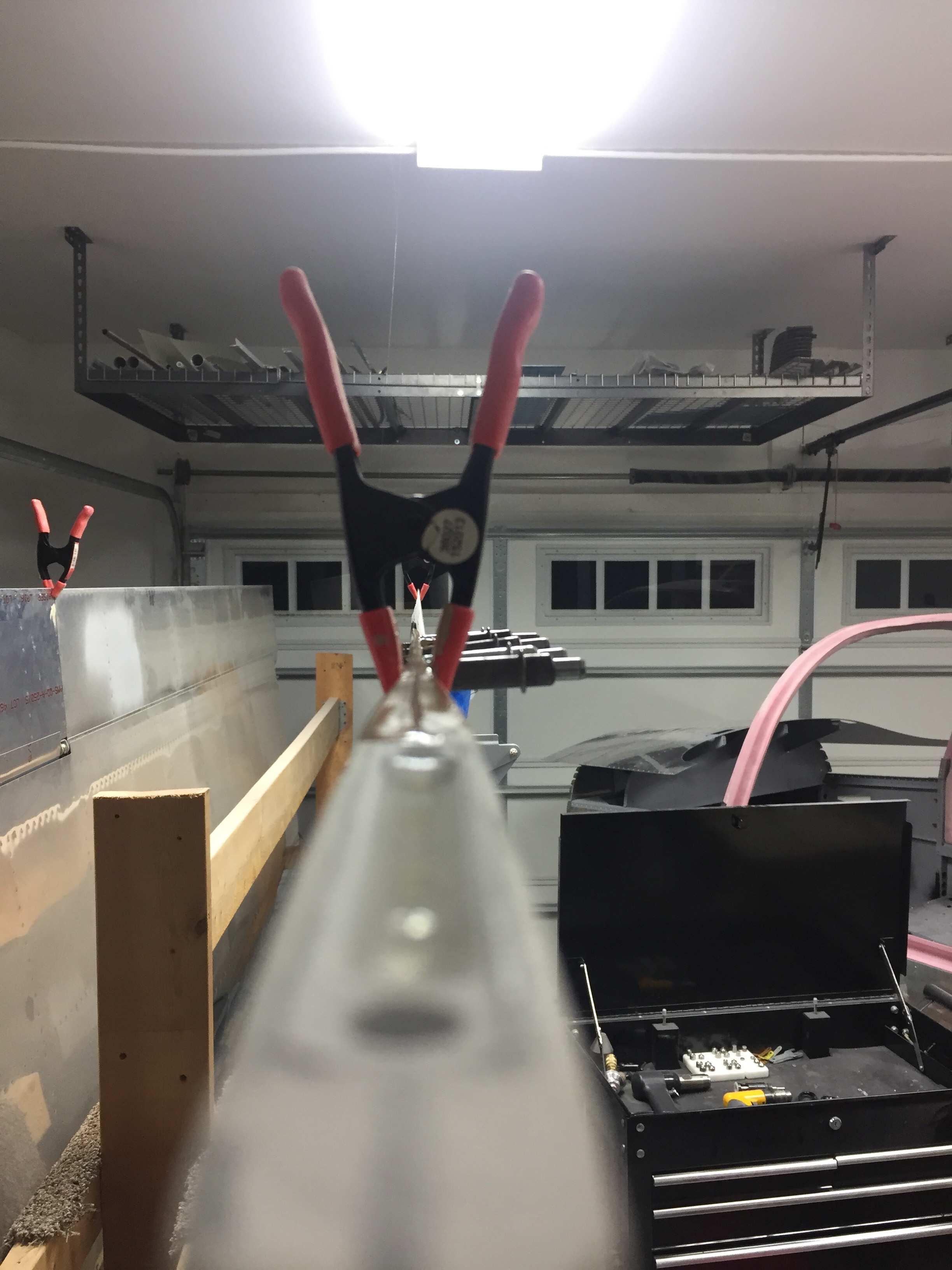
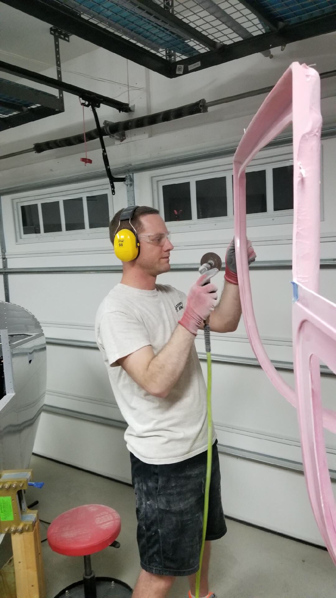
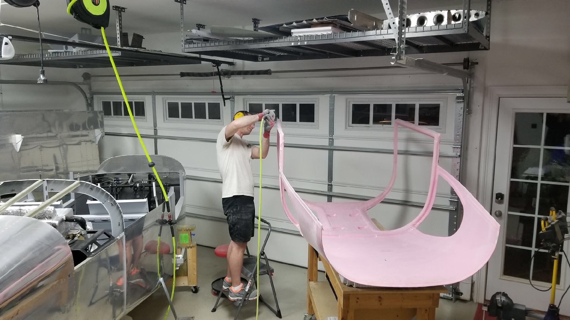
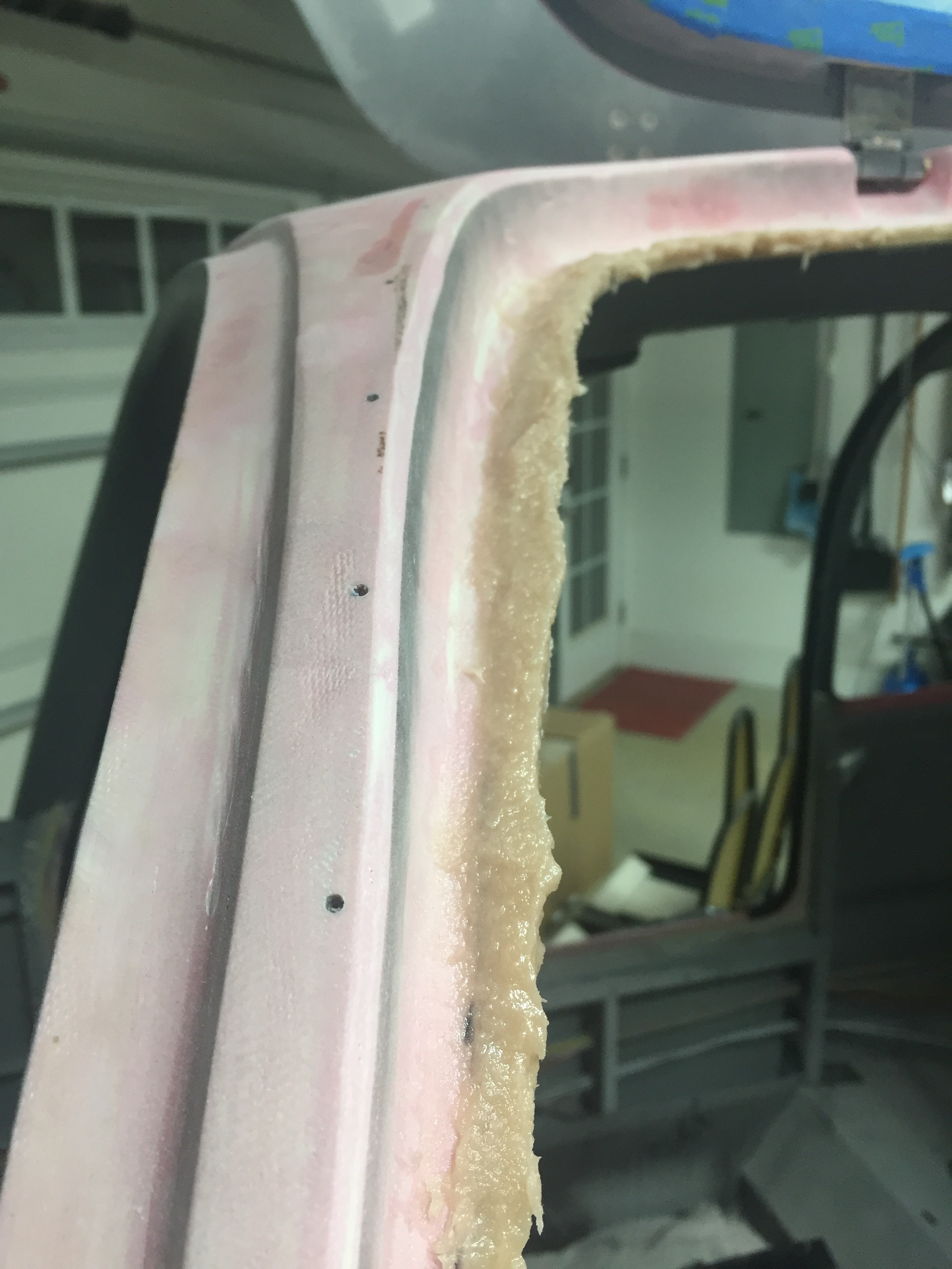
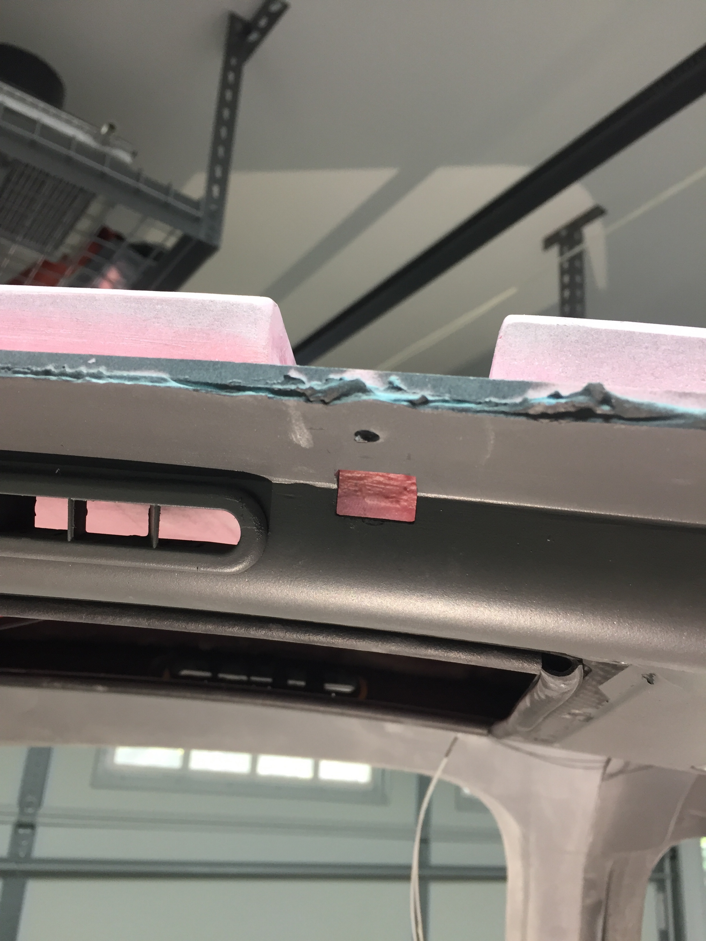
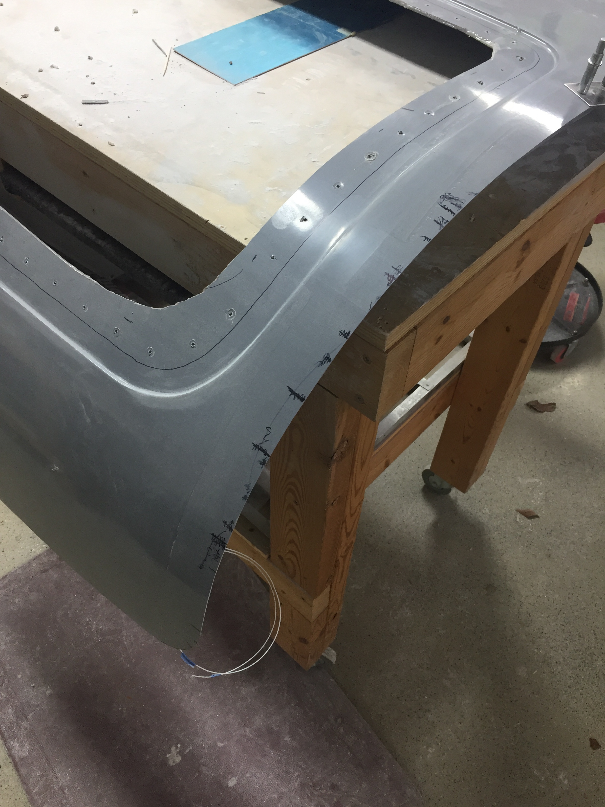
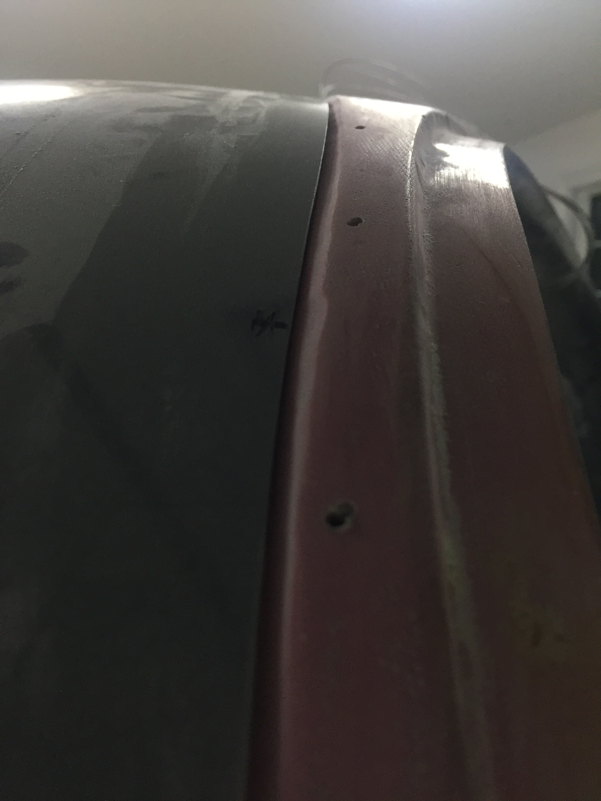
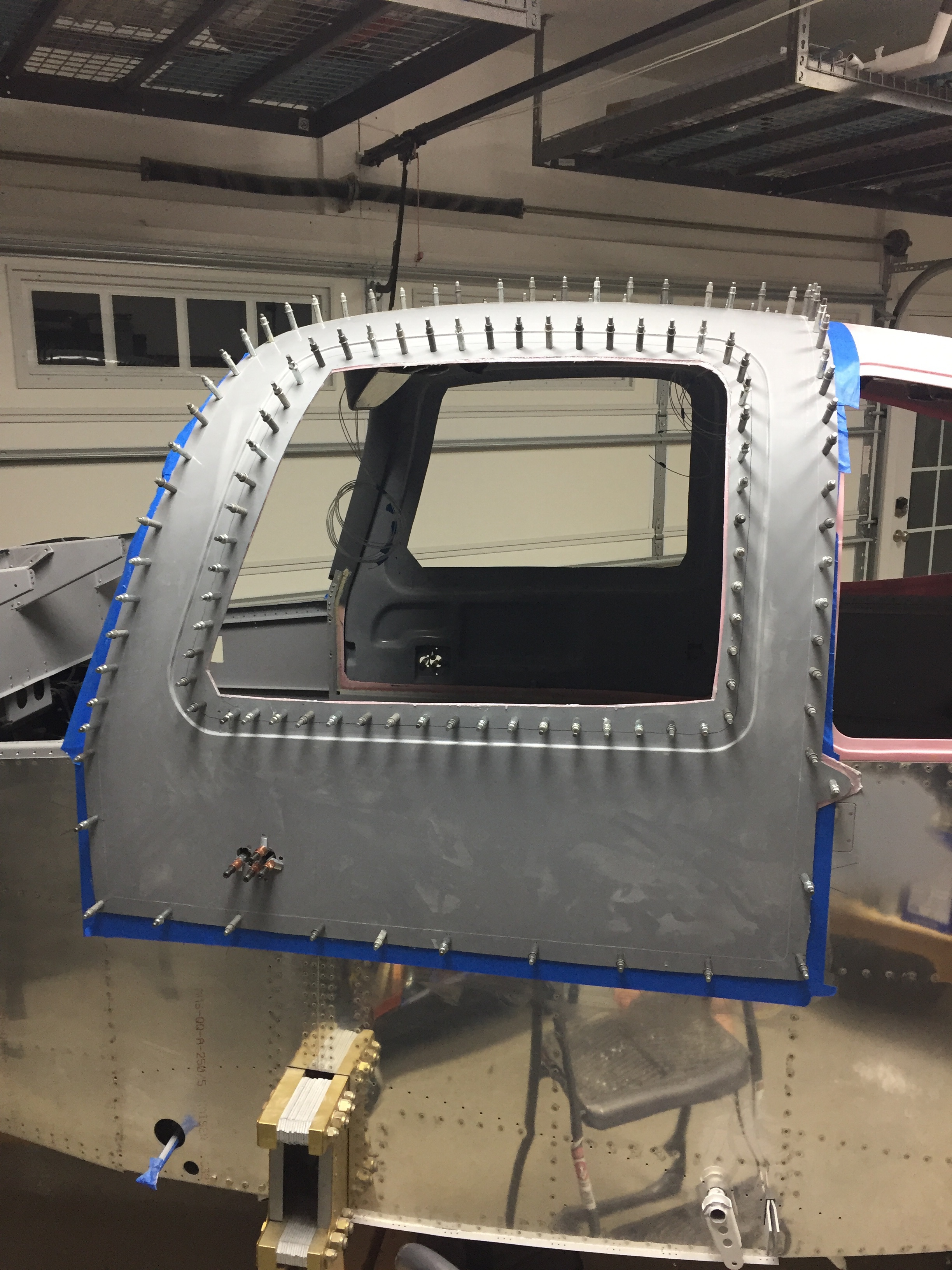
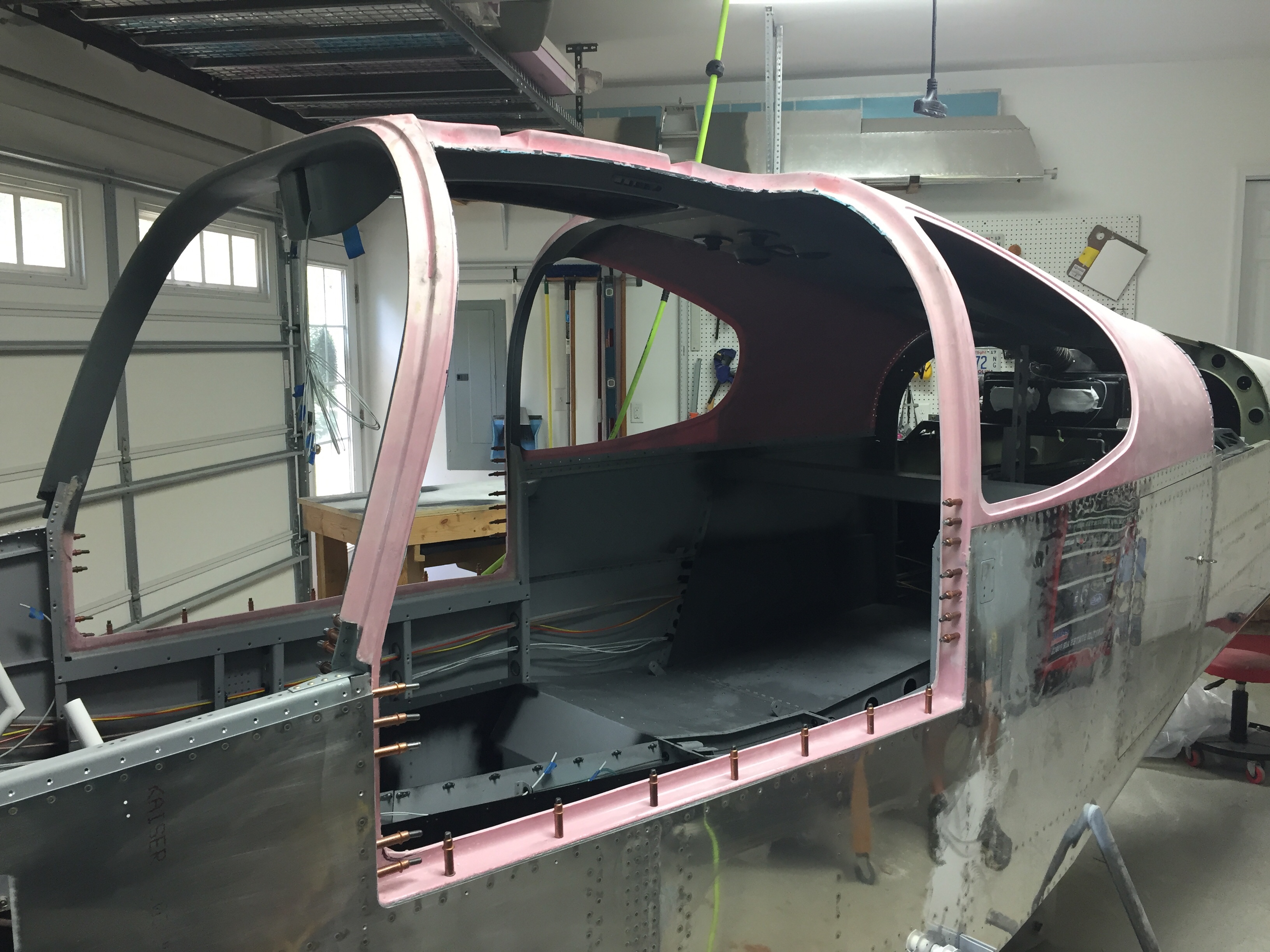
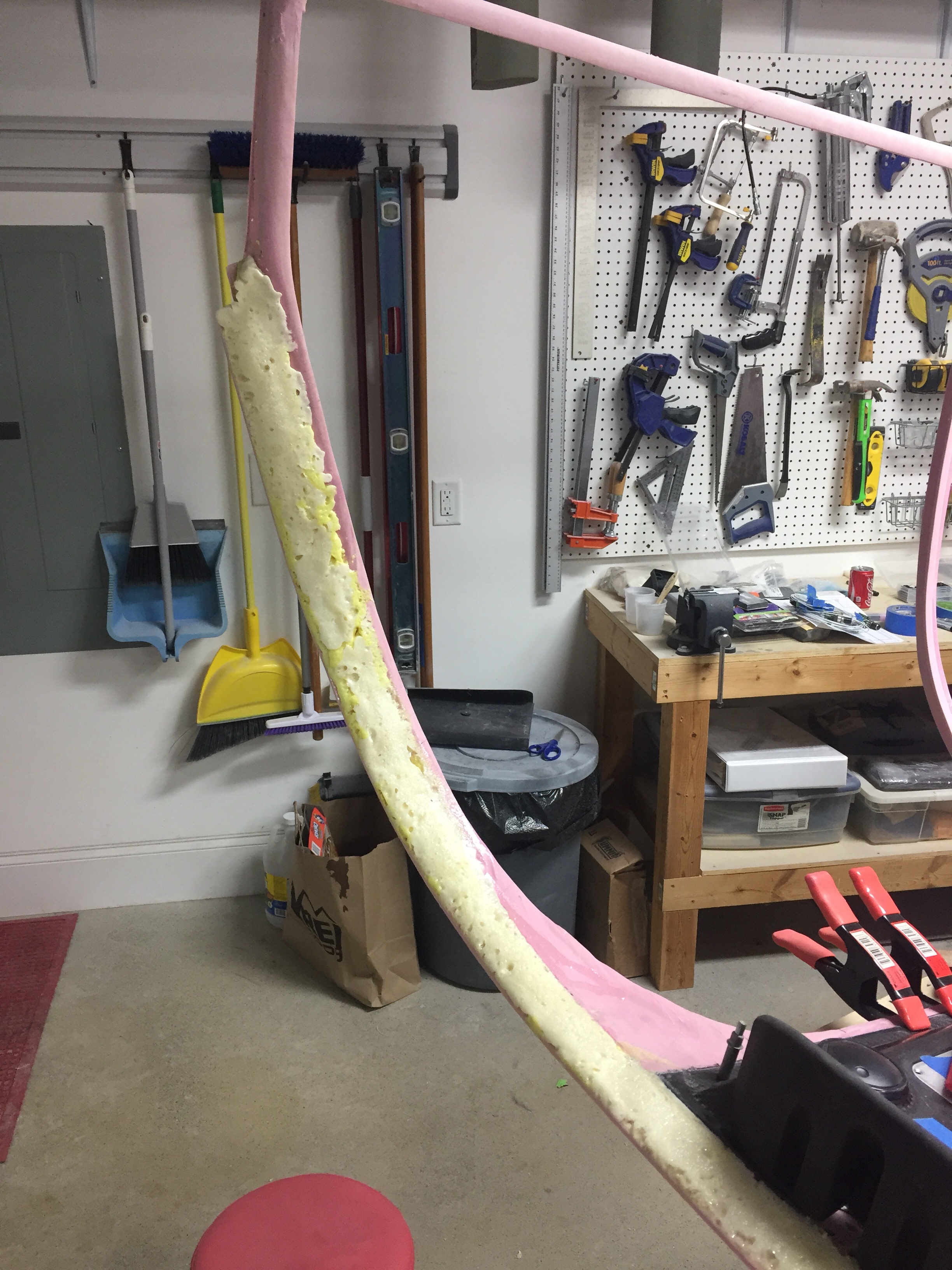
The next project is to prep for the door seal.  As most have done prior, I am going with an aftermarket seal that affixes to the door frame rather than the door itself.  Since the frame isn’t designed for it, a little prep work is required.  I needed to build back material for the seal to mount on that will put the bulb nicely against the door.  I purchased twice as much seal as needed so I could use half of it sacrificially to form the new lip.  I mixed up a big batch of epoxy and flox and used a baggy to fill the seal.  Then I took my time to press on just enough to hold onto the frame.  Once dried, I pulled the seal off which left a nice new structure all around the door opening.
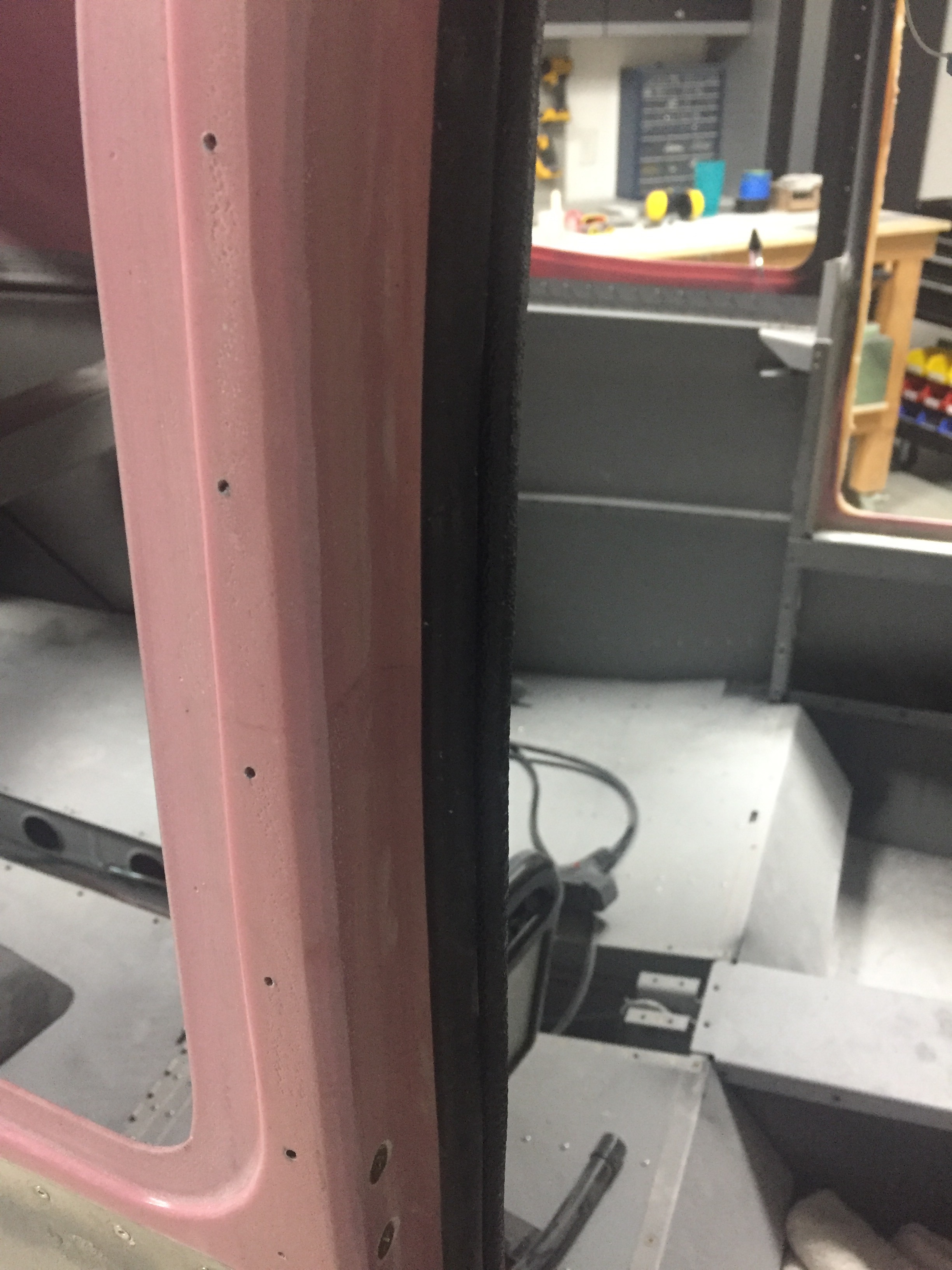
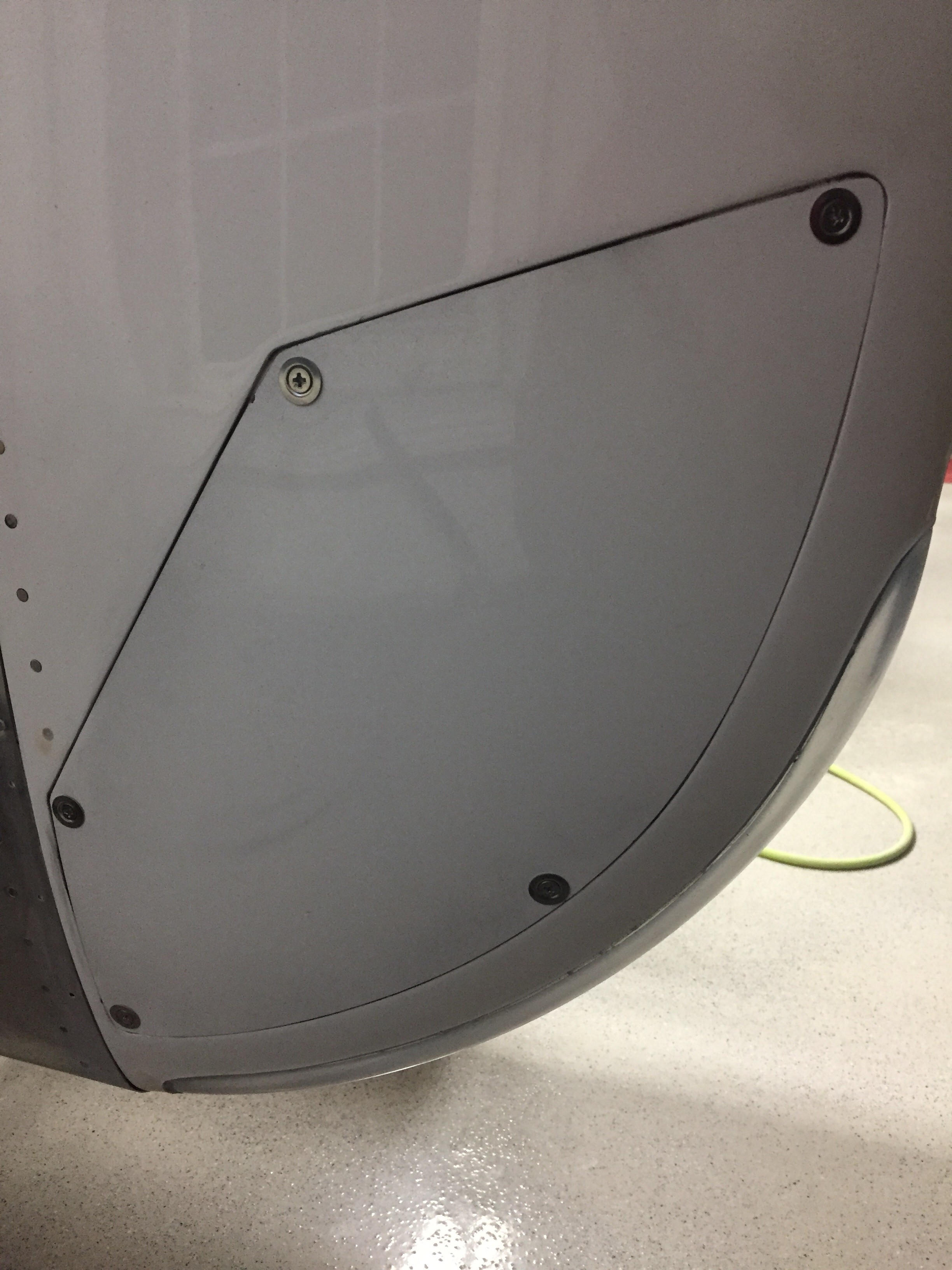
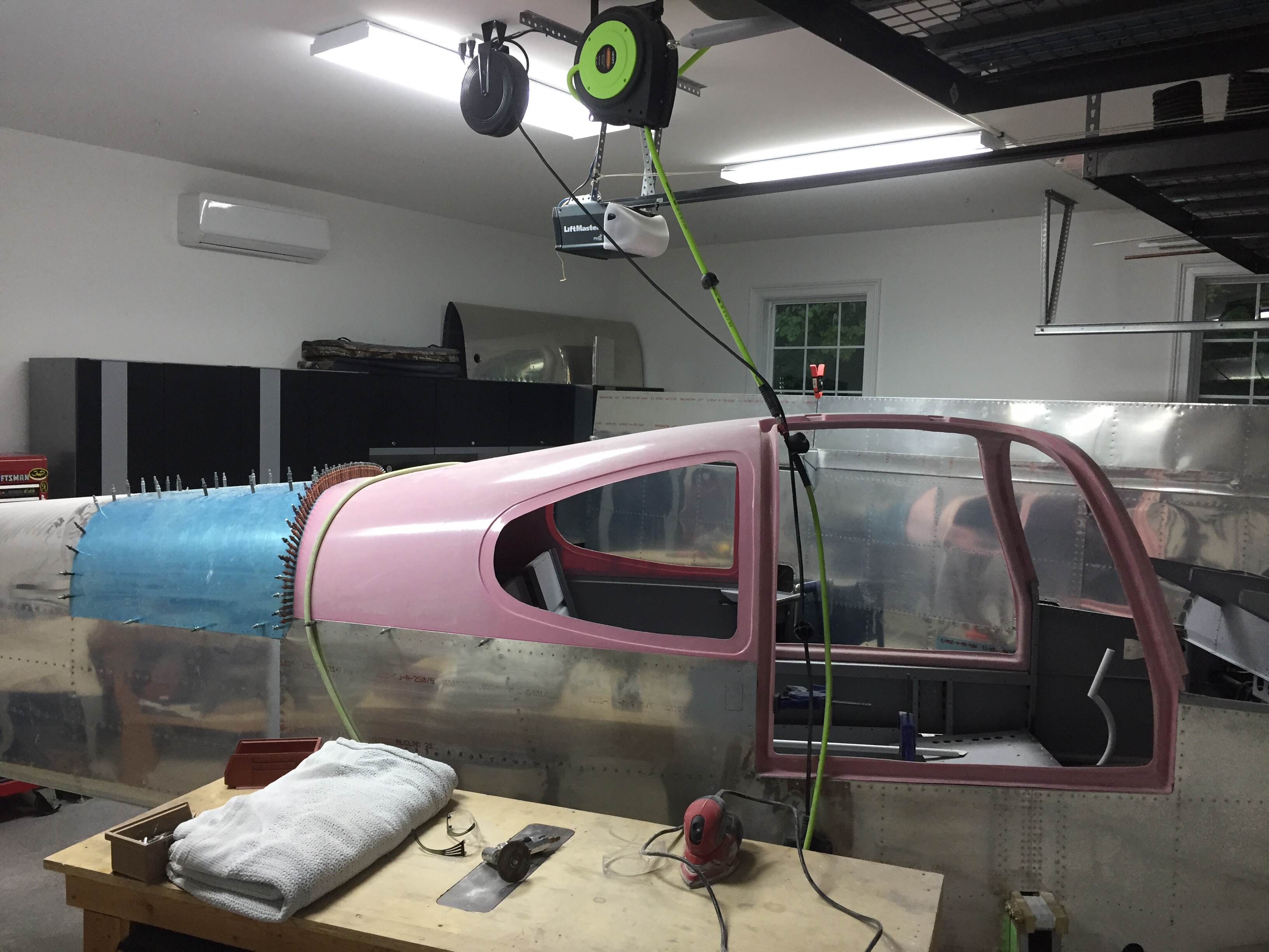
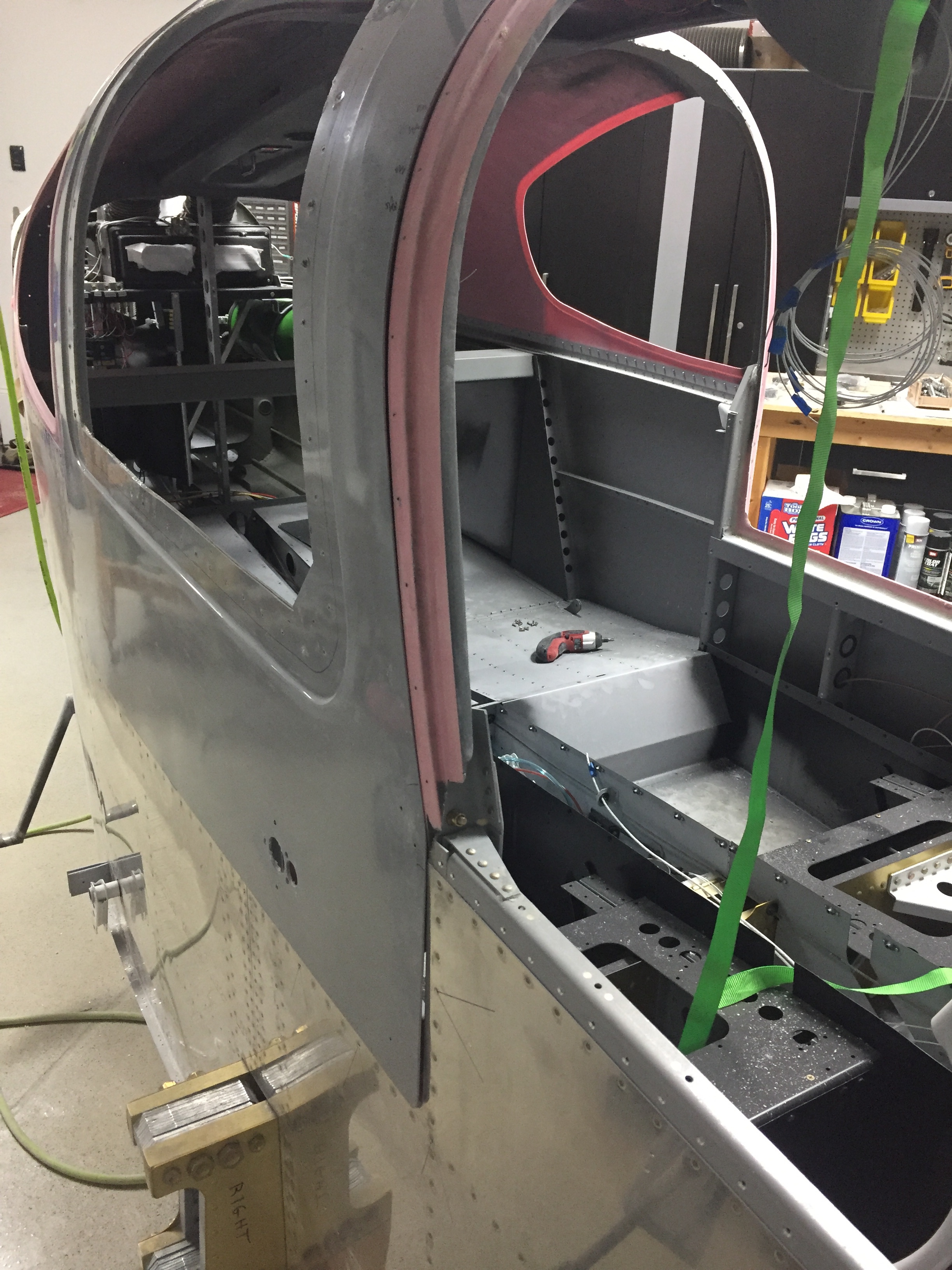
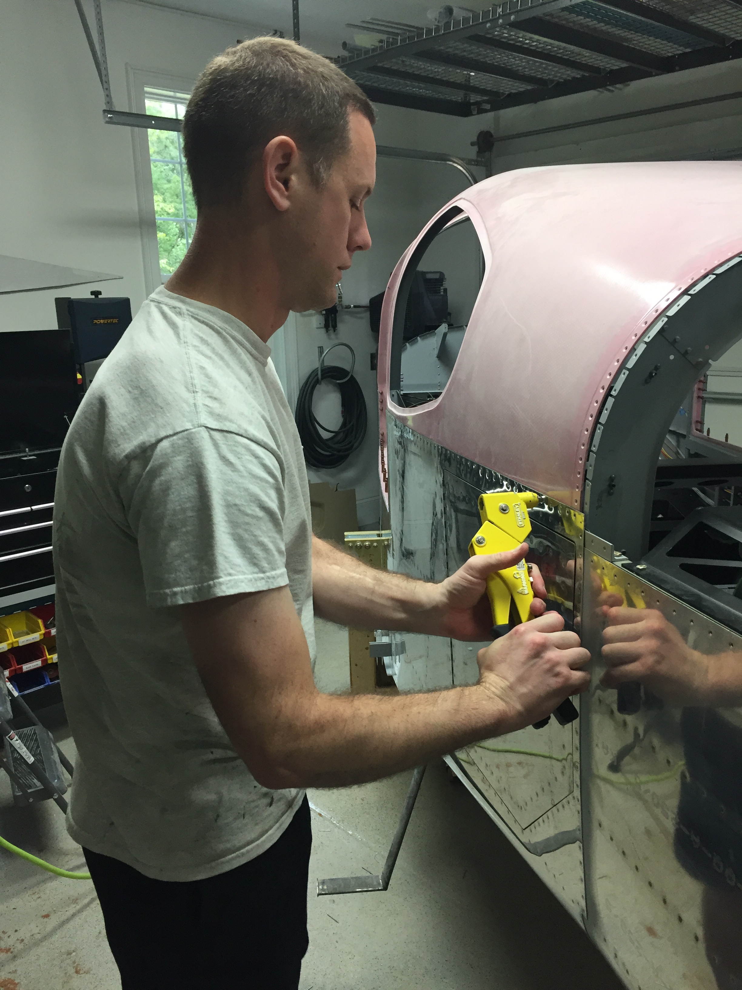
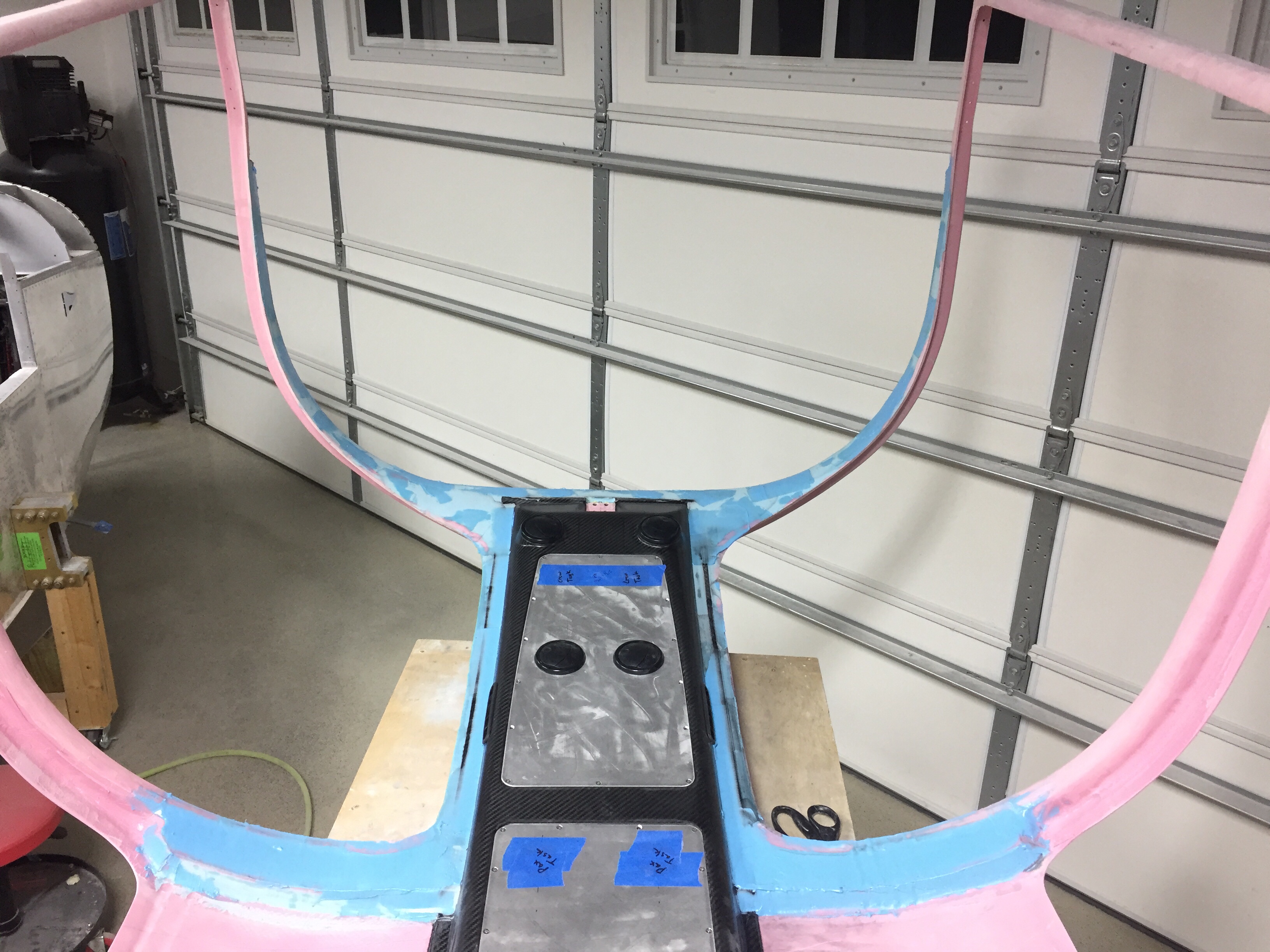
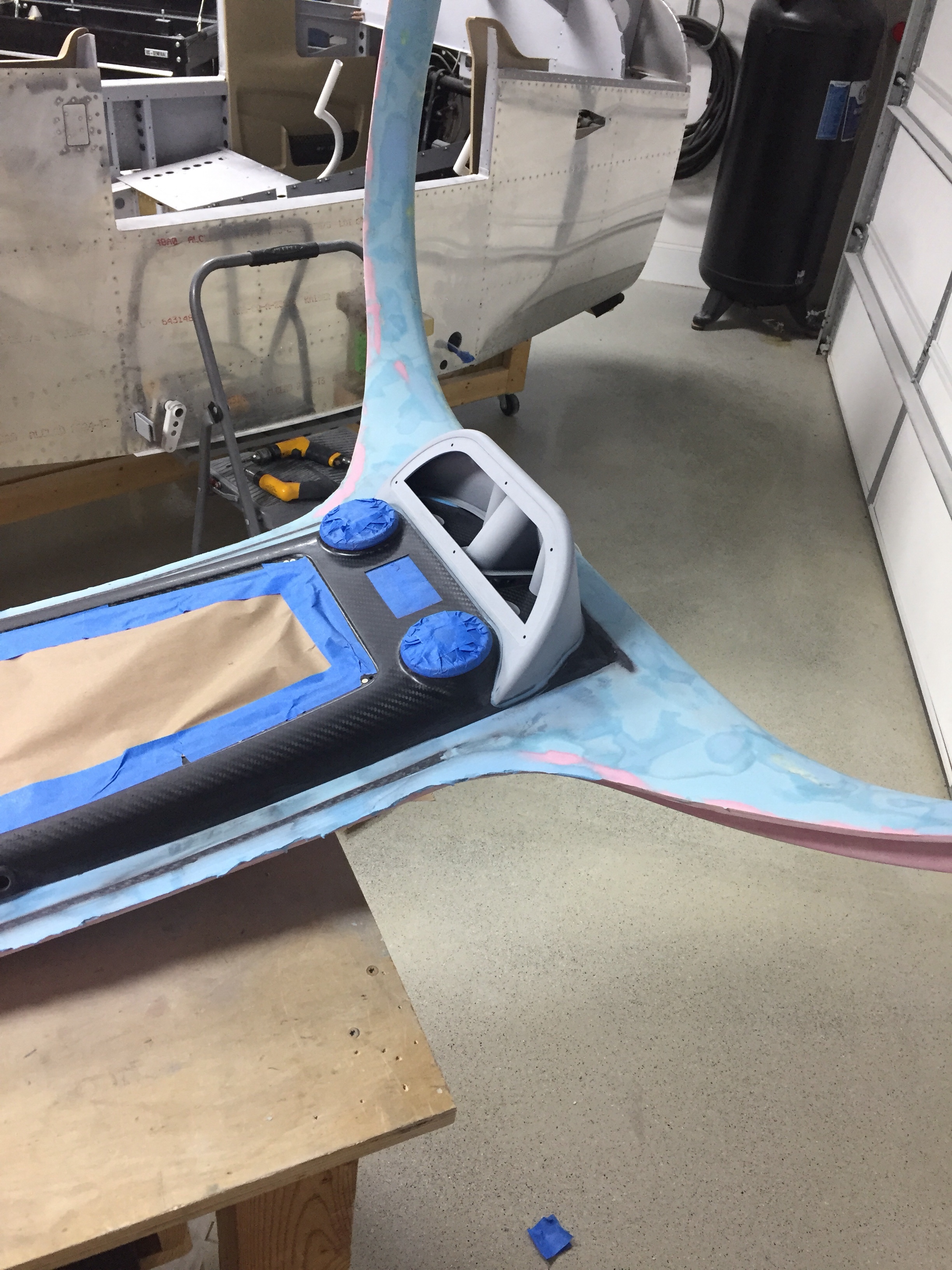
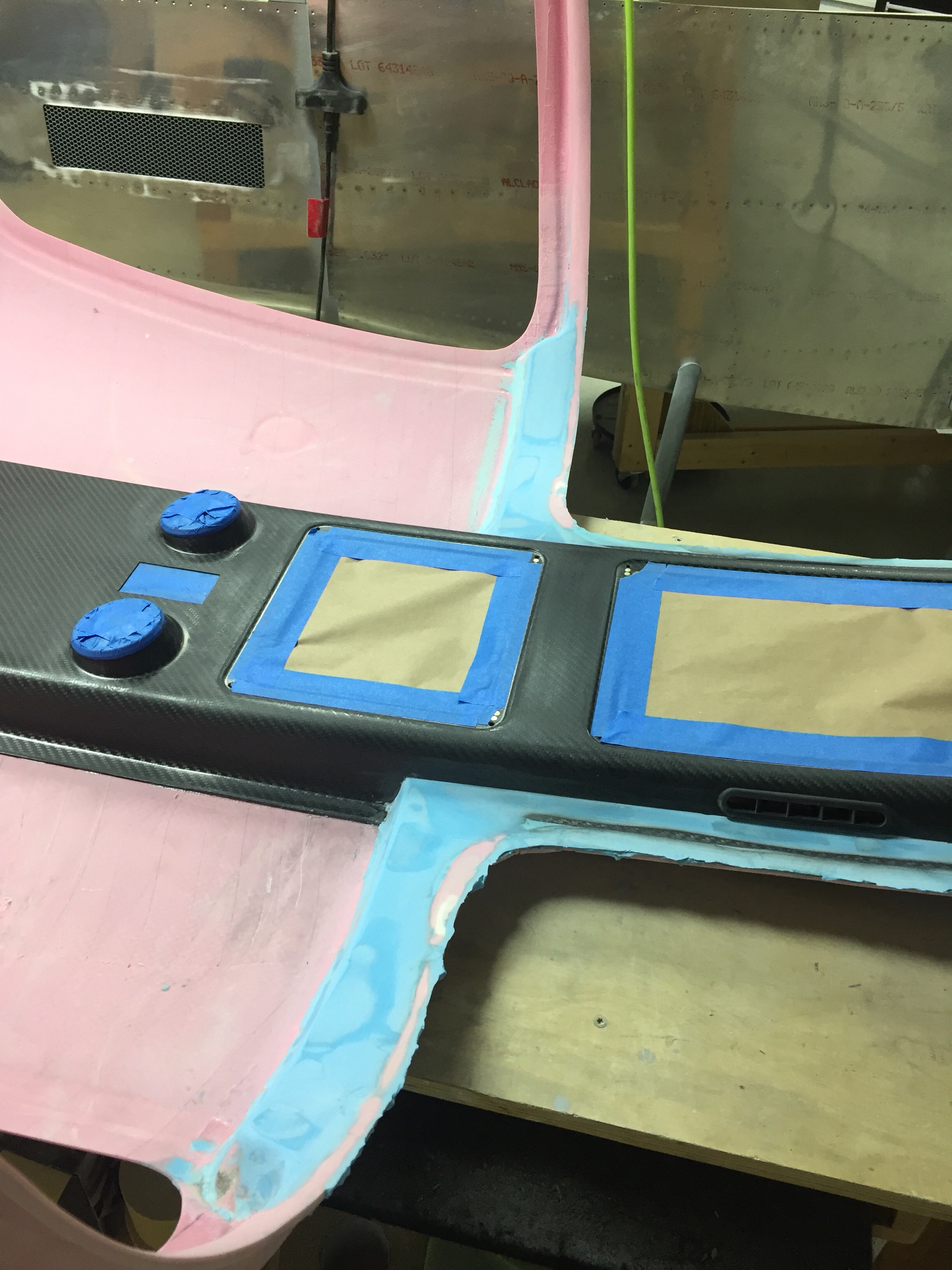
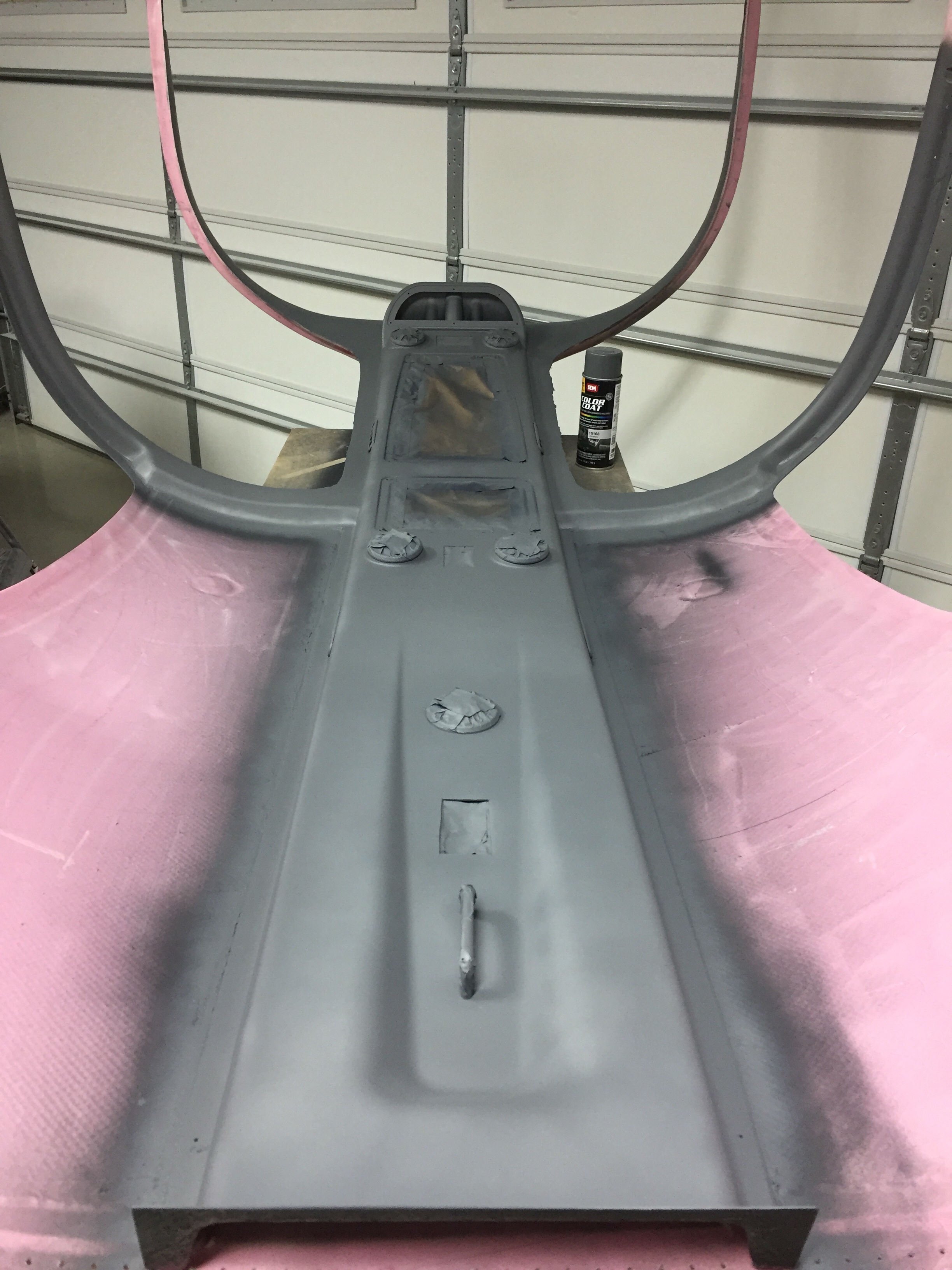
With the door on, I marked the areas that needed to be sanded down or built up a bit with filler to get a nice consistant gap all along the door lip.  Despite all the dust, it was a pretty easy task and soon enough I was ready to put on filler to smooth things out.  I did both the inside and outside.  I’m a little bummed that I’ll have to re-shoot some paint on the inside, but I can mask of the overhead console so that will make it a bit easier to blend.
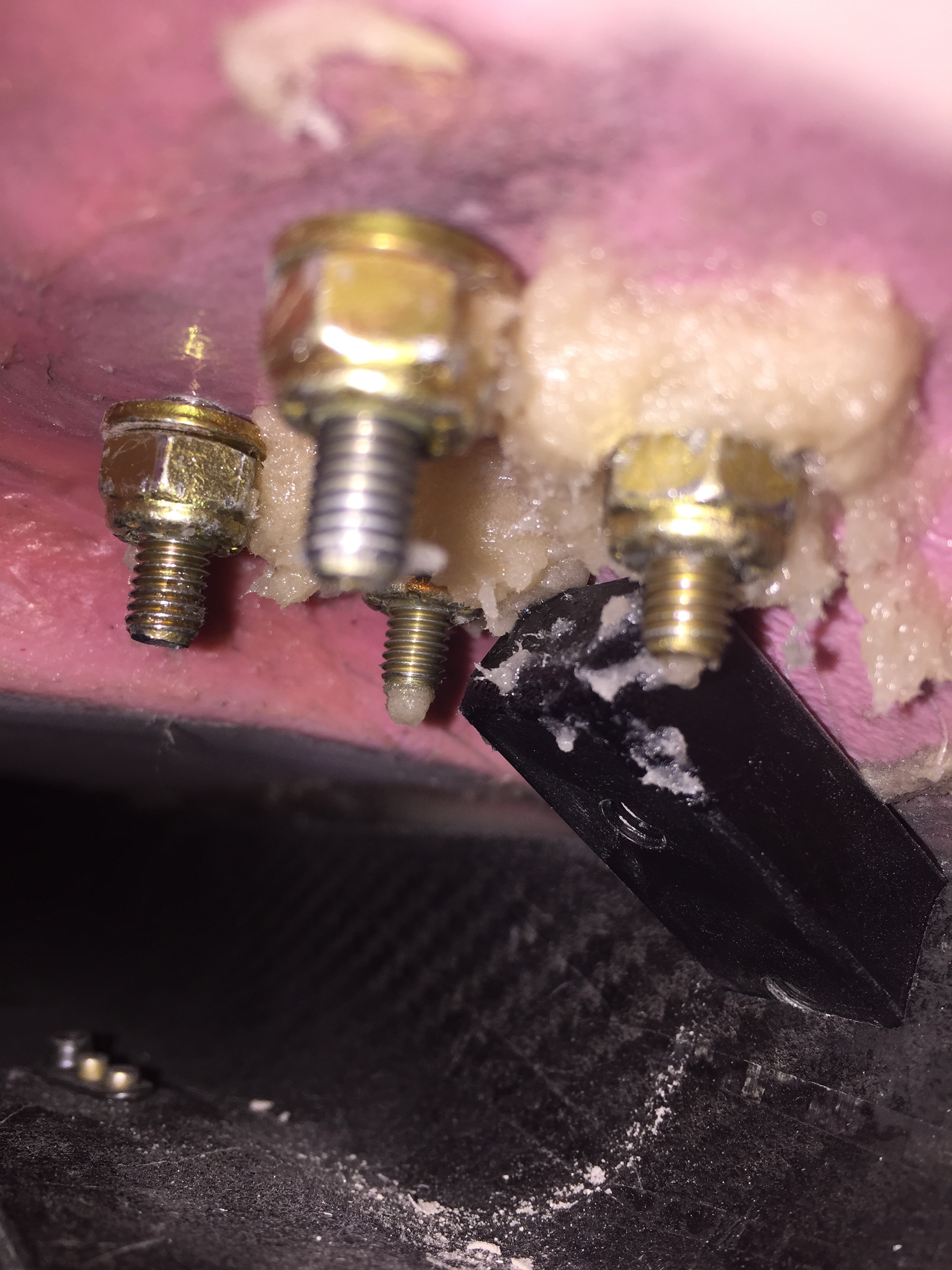
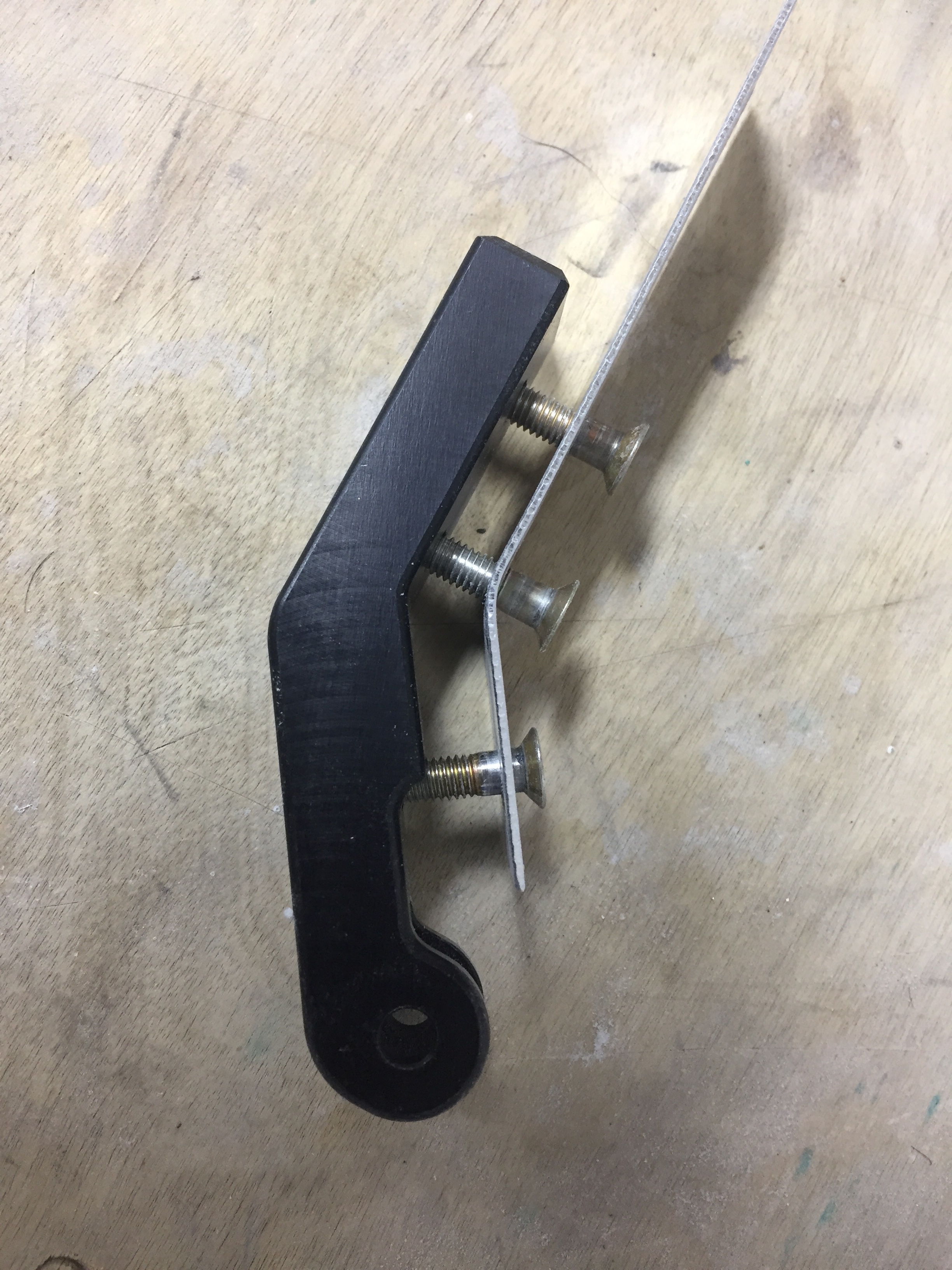
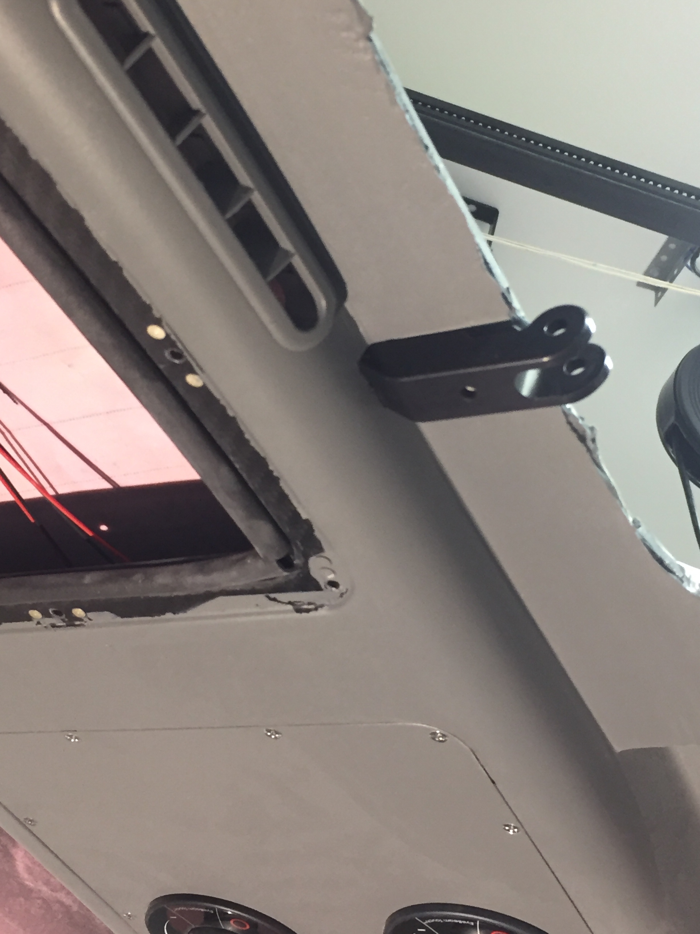
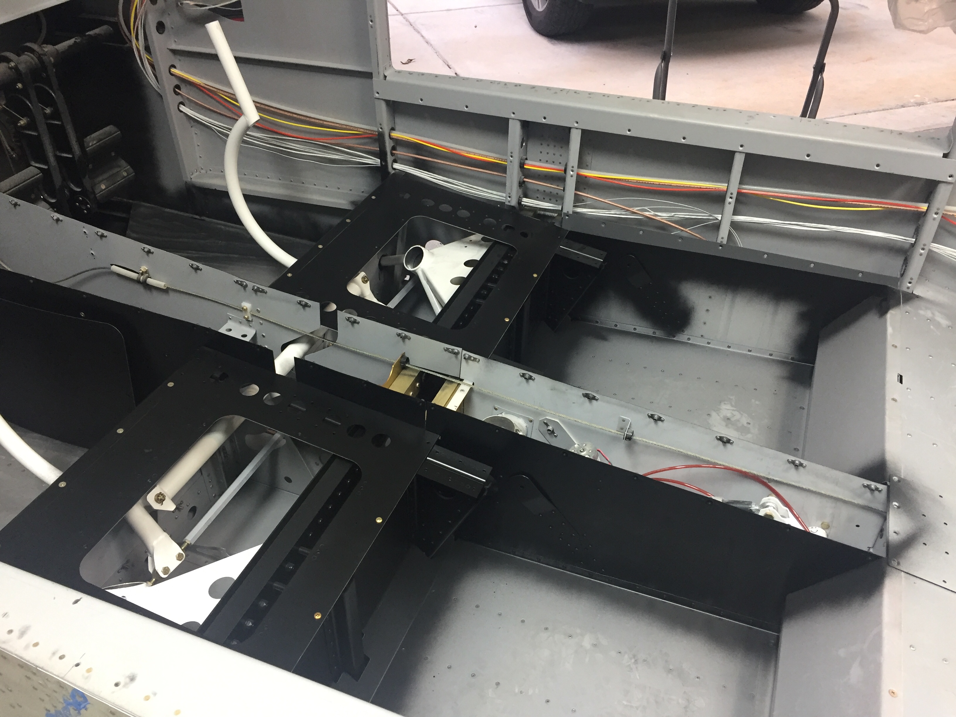
Meanwhile I built a bed up of epoxy and flox on the hinge mounts since a few of the washers and nuts didn’t sit flush with the cabin top due to the contour of the inside surface.  This allows the torque to be spread properly over the newly built up area.  I let the epoxy cure about 75% then put the washer and nut on so it compressed the fill into place.  After it cured I finally torqued them to spec.
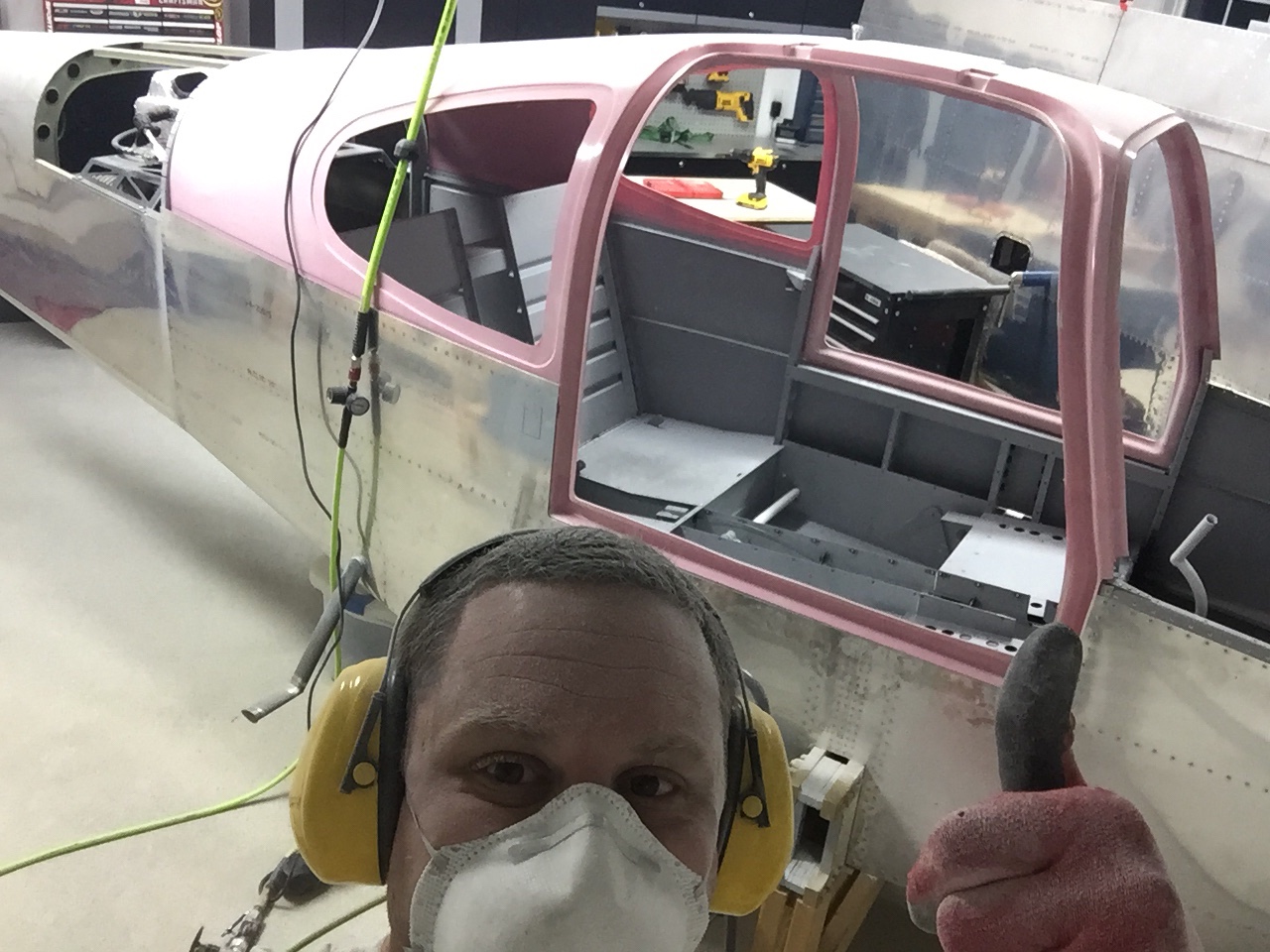
A few evenings of sanding and filling later, the left door frame is ready for paint on the inside and the seal to be installed.  The right door is coming along with initial sanding and filling happening now.  Once the windows are in, I’ll fill the final door gap and finish the rest of the door frames.

Rack ‘em and stack ‘em

I needed to get the door pins installed so that I could lock the doors in their proper location to get the final trimming done.  It’s a cart before the horse thing, as it’d be nice to get all the trimming done but you need the pins first.  But to get the pins, you need to trim the doors.  Lot’s of half finished steps to complete the other steps here.

I’m using several aftermarket modifications as well.  The PlaneAround center latch is a no-brainer for its functionality and safety aspects.  It provides a cam in the center of the door to help close the door and ensures both front and rear pins engage the fuselage to keep the door closed.  It also basically makes it impossible to close the door with only one pin engaged.  The danger is potentially life ending, as several accidents have been caused by doors opening and separating from the airfarme.  Nothing to joke about here, you have to do this right and know the severity of the impacts.

I’m also using the low profile handles from Aerosport which are very nicely built and are a bit more high class than the standard Van’s handles.  With that being said, it means following three sets of directions that all leave a bit to the imagination.  Of course, I don’t read directions well so I started off by cutting my door racks according to the stock plans, not in half as I should have.  That looked like an expensive mistake, but VAF came through and I got a new set for the cost of shipping thanks to a very helpful fellow builder.

The door rack and gear system is simple once it’s all put together but is a bit challenging in assembly.  I was able to work through the plans, however, and soon had all of the parts cut, created, and cued for final assembly.  It all comes together very well in the end as long as you take time to ensure a smooth operation of the mechanism.  I’ll be filling in around the nylon blocks on the door’s edges so aren’t too concerned about looks here.

I also added cam locks to be able to lock the doors.  While they aren’t completely bullet proof, they will provide some security and deterence for people to not mess with the airplane or its contents.

Hey don’t forget

Tip for other builders.  Don’t forget to follow the steps that aren’t in the plans that you don’t know about but absolutely have to do in order even though nothing says to do them in order.  For example, the door strut bracket that attaches to the top of the cabin.  Yup, I forgot that.  I realized that in a moment of sheer panic and terror about 3 am one morning.

The strut bracket is a bit rudamentary from Van’s so I had ordered a very nicely CNCed version from Sean at PlaneAround.  Those have been sitting in my parts bin for two years now and despite all my hard work at the overhead console and finishing the interior of the cabin top, I forgot to install them.  It would have been a five minute job had I remembered.  It turned into a five hour job.

I would have to cut a hole in the overhead console and grind away part of the filler on the cabin top without screwing anything up to make this work.  Fortunately, I took my time and went at it very methodically.  I located the exact position it needed and drilled a few holes to start opening up the rectangle for it to slide in.  I got pretty luck and it proved to be a nice finished fit once all the filing and trimming was completed.

I then made up a jig to locate the screw holes since I couldn’t drill or mark from below due to interference of the console.  The jig allowed me to drill pilot holes from the outside and then enlarge to get the proper alighnment.  Worked like a charm and in no time the first bracket was screwed on.

As with everything, the second one goes quicker and easier so in one evening I corrected a big mistake with really nice results.  I doubt anyone could tell that they were installed out of sequence and looking back I wager it was even easier this way vs trying to sand and sculpt the filler around them while filling in the console.

Let me get that door for you

The epoxy dryed overnight and the next morning I was ready to start cursing clecos as I pulled them out of the cured doors.  A few were kinda tough and I ruined some clecos, but eventually all of them were out and I was left with two doors!.  The next step is trimming the outer flanges to fit flush inside the cabin top and fuselage.  It’s a tedious task as you really need to trim them to fit but they need to fit to see where they need to be trimmed.  I took a tip from another builder and created a template to cleco on the door and fuselage instead of leaving tabs on the door flange itself per the plans.  This allows the door to slide into the frame but ensures it’s held in the same place when test fitting it.

Slow and steady wins the race here, with a lot of sanding/grinding/fitting/repeat to get it just right.  I am neither slow nor steady.  So after about 15 times of test fitting and removing, I went to town with the die grinder and poof, too much gone.  Cardinal sin of building a RV10 door.  When all the dust settled, I realized that the doors themselves weren’t too small but I just didn’t take my time to fit them.  My scribe lines from the factory were WAY off and oversized.  I was shocked at how much material I had to remove to get the doors to sit flush.

In the end, I put a chamfer on the cabin top and the door flanges to get a nice fit that was a complete waste of time.  Since I’m using the McMaster Carr seal, I don’t need a beveled edge on the door and frame and will need to build the cabin top / door up in several places anyway to make the two surfaces flush.  Oh well, I knew doors would be a pain so par for the course.  Nothing was too bad that can’t be fixed, so I still looked at it as a success.

Once I calmed down, I got to work on the right side hinges which went on quickly and easily.  Wouldn’t you know it, I was ready to open the door for my lovely wife to get in her side of the airplane.  Except she wasn’t there and there’s no seat and it’s really dusty and I don’t want her touching anything yet since it’s not finished anyway…..

Dreaded Doors

The biggest and most dreaded part of a RV-10 build for most people are the doors. The are notoriously tough to trim, fit, and fill to get a nice result. However, they are critical in the safety and looks of the plane. And since I don’t want to mess up my hair while flying, I dove in to start closing up the cabin.

It’s commonly known the scribe lines and reference dimples are useless and my doors were no different. The dimples were a half inch off from each other So I matched up the two shells of the doors by eye and measurements. The first step is to trim the window opening and prepare the shells for bonding.

Fiberglass is messy stuff, so use proper PPE! I then did a rough trim on the exterior of the halves to get ready to bond them on the cabin top. You use the cabin top as a template to get the proper curve set while the epoxy sets. So I payed the halves on the top and prepped by drilling holes for the clecos.

I then began working on the Planearound center latch as another builder did, before epoxying the door halves together. It was much easier to work on the back side of each half before the pieces work together. It also allowed me to insert the gear box through one hole instead of having to cut the slot. Looking back, I wish I had done the entire door handle system while the door halves were apart, but I’m getting ahead of myself. I cut the reinforcement tubes and also ran wire for the door/access lights that I ordered from Sean as well. These are smaller versions of what I put in the overhead console and should light up the wing and step at night very well.

I’m also installing the low profile exterior door handles from Aerosport and again it was easier to do some preliminary work on those before the doors went together. Drilling the skins for the large block as well as the door lock and trim ring saves a lot of work later on.

I had a fellow flyer-buddy of mine come over and help mix flox and set everything in place. I chose to follow a few others by using clecos into the cabin top instead of tape, clamps, weight, etc. to get the curve. This worked very well except for one spot on the right side door where the door just would lay flat against my cabin top. I pressed on knowing I’d be doing some fill and finessing later. It takes a lot of epoxy/flox mix to butter the halves up. I filled the cavities near the center cam we slathered on the flox followed by pinning it all to the cabin top.

We cleaned up the excess flox that oozed out and I’ll start popping these off tomorrow. This is all the easy part!

Coloring outside the lines

Painting the inside of the cabin is much easier when the cabin top is removable, and with only a few items left to do before permanently installing the cabin top, I took the opportunity to put some color on the project. As mentioned earlier, the cabin interior will be a dark grey and black. I started by cleaning and prepping the tunnel walls and footwells. Most of this will be covered by the black carpet, but I wanted to make sure any areas not covered would be black. The SEM is really easy to work with and two nice coats provided plenty of coverage. I then used a low luster clear to help provide some further protection and sealant. I didn’t worry about overspray since the carpet will hide the imperfections.

The rest of the interior is the dark grey so I prepped again and sprayed the remaining parts of the cabin which will not be covered by Aerosport panels. I’m not a huge fan of painting because it’s so much prep work, but the results are rewarding. It’s nice to see a finished surface finally.

Sean also sent me his updated LED lights for the overhead so I got those wired up and installed using nutplates and the standard micro-Molex connectors. I really appreciate working with fellow builders as vendors because they provide great support. Upon receipt, there were a few LED boards that didn’t work properly. I gave him a quick text and new ones were on the way in a few days. He later did some troubleshooting and found out the wire used to secure the boards was shorting them out. So I pulled the wire and simply filled in the back with black silicone and had no other issues. The lights are great quality and very bright, providing a nice pattern of light. Night loading should be very easy with these on the overhead and in the doors.

As typical, the big moment of putting the cabin top on for good was somewhat anti-climatic! I am glad I won’t be Atlas-ing the thing on and off anymore, as that was getting a bit tiresome. It is secured with a ton of pop rivets on the rear and screws up front. The challenge to it, however, is setting the frame in a bed of flox all around the door areas. I had the Mrs. come out to help mix epoxy and spread it on the fuselage. Even with slow hardener, we were pushed for time getting it all mixed, applied evenly, and positioning the top on just right. I chose not to drill the screw holes yet and clecoing the cabin top was much quicker and easier at this point.

I cleaned up the remaining flox from inside and and put the rivets in. All in all, a bit stressful for us but a rewarding step seeing the canoe form finally disappear! The finish kit is coming next and I’m pretty pleased with the amount of progress I’m making this year.

Meanwhile, overhead

While the air con project was underway, my time was split between it and the cabin cover. After rough fitting the overhead and wiring it for the lights, I had to start the cosmetic work. My first task was to contour the forward door / windshield supports. Others have left these and just cleaned them up while some have filled it in to make it look just a bit cleaner. A few folks will run conduit in the jog and then fill over it to route wiring to the overhead. I chose the middle option, just wanting to fill them in for a fuller, more finished look. My wiring will be going through the center post so no need for conduit.

I used the closed cell spray foam insulation and piled the stuff on. It’s a messy job and I had to use quite a bit since it’s not exactly sticky and wanted to run off on the more vertical surfaces. After it cured for a day, I used a flexible saw blade to do a rough cut. There were a few low spots and a lot of holes that needed filler. I also floxed on the overhead console after a good pause to make sure I’m not getting ahead of myself. It was a straight forward process and is super solid now.

Now that the overhead is in, it’s time to start making it all look good. Out comes the Super Fill and the mixing board. I really like this stuff, it’s easy to measure (2:1) and easy to mix up. Best of all, it’s simple and easy to apply and pretty forgiving. The sanding is trouble free as well and it’s very light. Really, it’s just the best and I regret not using it before on the fiberglass tips, etc.

I mixed and applied for a good hour the first night and got the overall shape done along with filling in the overhead. I’m not worried about the areas covered by the headliner so that saves a lot of surface area that I can essentially ignore. I cleaned up the aft door supports as those will stay as is. I also installed the switch console and filleted the seam between it and the overhead. This seam won’t be perfect but it just makes it look a little cleaner, albeit not one solid piece.

And so it went for four or five evenings. I start by using my sanding blocks to clean up the now cured filler. After it’s all smoothed out and I can tell where additional filler is needed, I mix it up and apply. Then I moved onto the A/C or whatever other project of the evening is. It really hasn’t been a bad project and it’s rewarding seeing it take shape.

Finally, it was about as good as it is going to get, so I used the SEM high build primer to highlight any pins holes still hanging around. I few touch ups with some glazing compound made it all ready for the first coat of paint.

I sprayed a few coats allowing each one to flash and as always, the Color Coat provided good coverage. I am somewhat concerned that I’ll have some adhesion issues, as a few spots that will be covered by the headliner chipped pretty easily. The carbon has a very hard epoxy and even though I scuffed it, I’m not sure I did it enough. I should have also used an adhesion promoter looking back. I’ll use that for the rest of the carbon and the panels. Overall, I’m pretty happy with how it turned out and while it is not perfect, it is more than good enough for me.

So I changed my mind, cool it.

I’ve been doing a lot of research and discussion with folks who have installed air conditioners, especially the Flightline setup like mine. The general consensus is that it’s marginally effective at best. My standards aren’t extremely high, as the AC in the Diamond we fly just takes the edge off but doesn’t really cool like a car would. Others with the Flightline system have added a second condenser and one or two have routed the intake from the bottom to the side skin to avoid the exhaust mixed heated air. As my original commitment to John at Flightline was to design a side intake and exhaust, I decided to dive in and redesign pretty much the whole dang thing.

First, an overview of the setup. An intake on the bottom tail skin catches air and directs it through 6″ flex duct up and 90 degrees forward where it turns 180 degrees and goes through a 12′ square condenser. A 12″ puller fan helps air flow volume so it doesn’t rely solely on ram air pressure. Then, it heads back into a 6″ flex duct, makes another sharp 90 degree corner and exits out the bottom skin. It’s a lot of direction changing and restricting of the air.

I began by taking everything apart and checking out how it was all pieced together. The first thing I noticed was the mounting plate for the fan actually covered a 1/5 or so surface area of the condenser. Additionally, the system didn’t use basic air velocity and volume principles, so it was constantly going from small to large volume spaces with many restrictions.

My goal was to facilitate air flow through the shortest path with the least resistance, thereby providing more efficient flow and better heat exchange in the condenser. I studied several factory AC setups such as the Cirrus, Bonanza, and M350 and noticed no ducting on the intake and direct exhaust from the condenser through the skin. The condensers were also significantly larger in surface area. So the new design would be to pull ambient air from the tail cone through a larger condenser via the same fan and exhaust it through the side skin within the shortest path possible. The ambient air is provided through an louvered intake near the horizontal stabilizer.

So, I bought a 16″ x 12″ condenser and set about molding a plenum from the condenser to the fan. If I had a vacuum table, this would have been perfect to keep the mold to share with others, but unfortunately I had to lay up fiberglass and the molds were trash.

The layup came out very nicely despite destroying the mold and was a perfect fit around the fan casing. A simple bead of silicone should seal it up nicely when installed.

Next was to do a mold from the fan to the skin for the exhaust. I figured up the square inches of the fan and worked within the stringers to maximize the opening area while keeping it just under the square inches of the fan. My thought on this is using the Bernoulli principle and having the smallest (relative to the entire air path) opening creating the highest velocity at the skin. This will in theory help the exhaust penetrate the boundary layer air around the fuselage, which has also been a concern from others.

I used the same fan mounting plate since it’s no longer restricting air flow. The exhaust plenum as a lip molded in to use as a mounting surface on the skin. The weight of the setup will be supported from the stock tray so the plenums aren’t load bearing.

I put it all together and hooked up the fan to check it out. There is significantly more air flow going through and I’m cautiously optimistic that this will create a much better performing system.

Next up will be mounting it all in the airframe and cutting the skin.

Success hinges on the tips

Some time ago, I received a large package from Aveo containing a brand new set of their ZipTips, wing tips with slick looking LED’s. I’ve been waiting on these things for years, ever since I saw them at Sun ‘N Fun in 2013. I’ve hounded poor Damien at Aveo relentlessly but it paid off with an opportunity to help them out with profile shaping and some prototype testing. In the end, I think it was worth the wait and I’m really looking forward to seeing these things all completed.

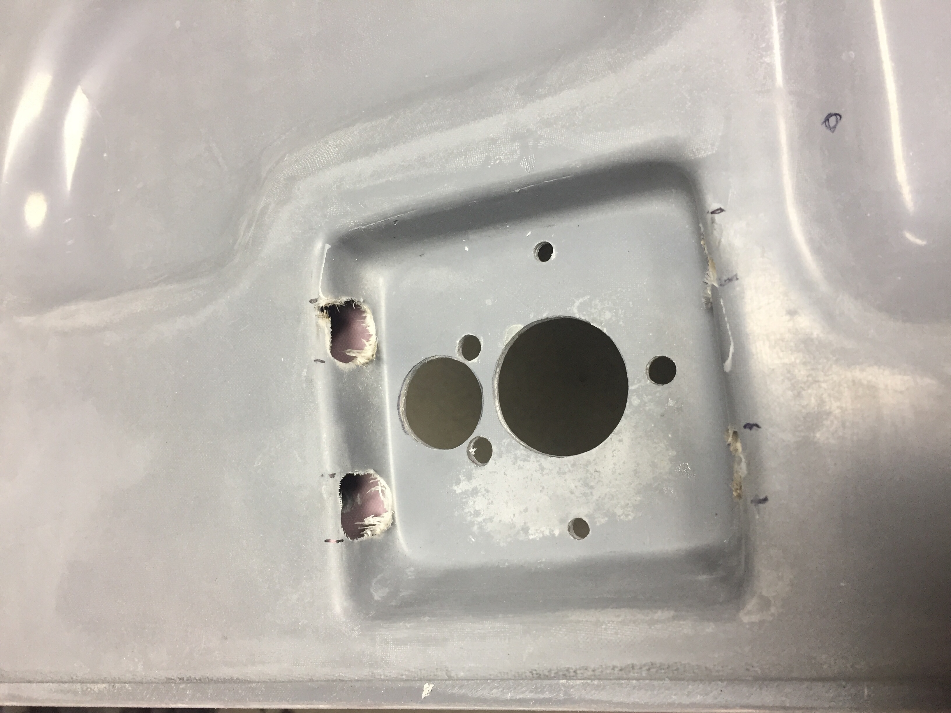
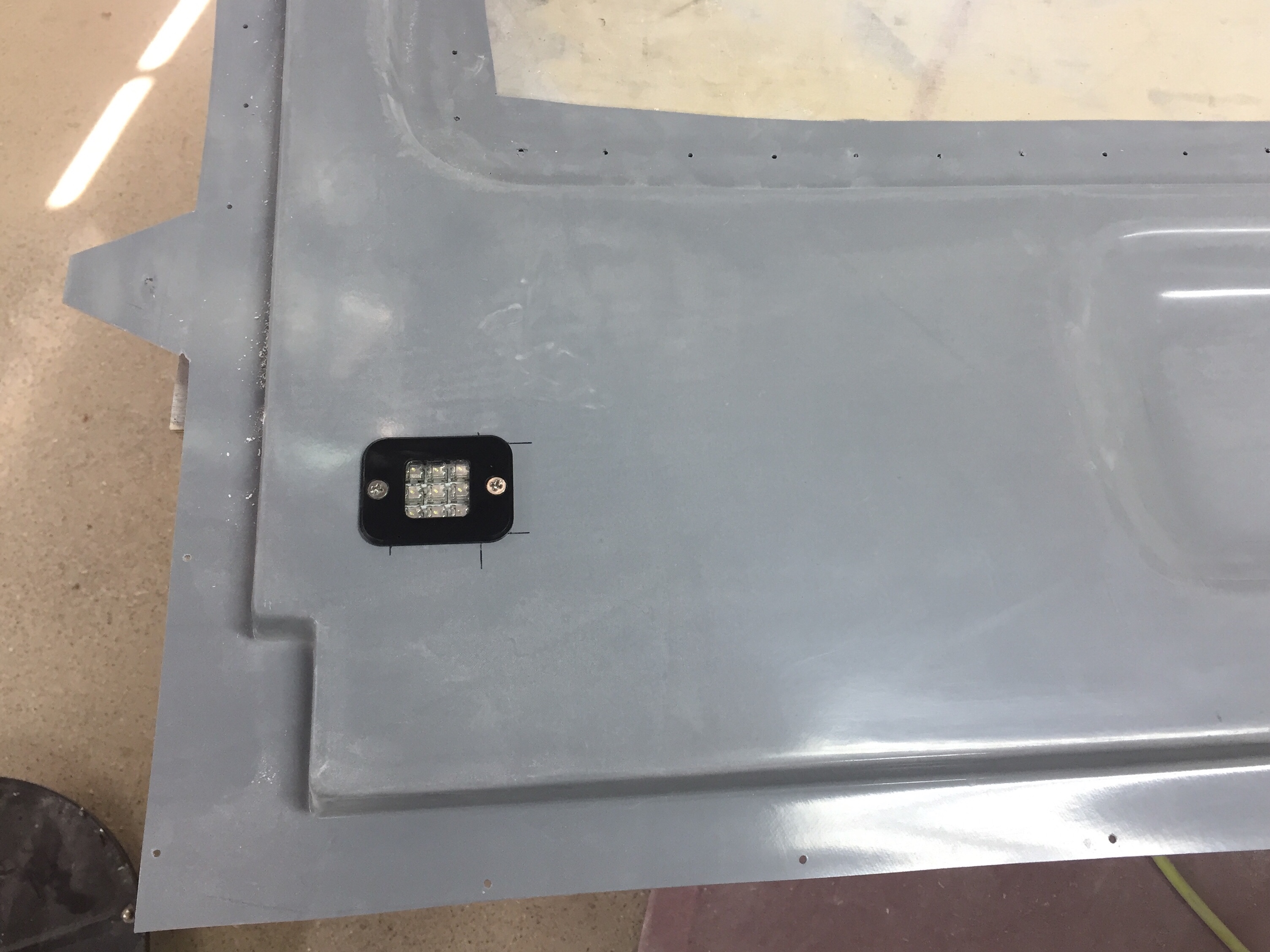
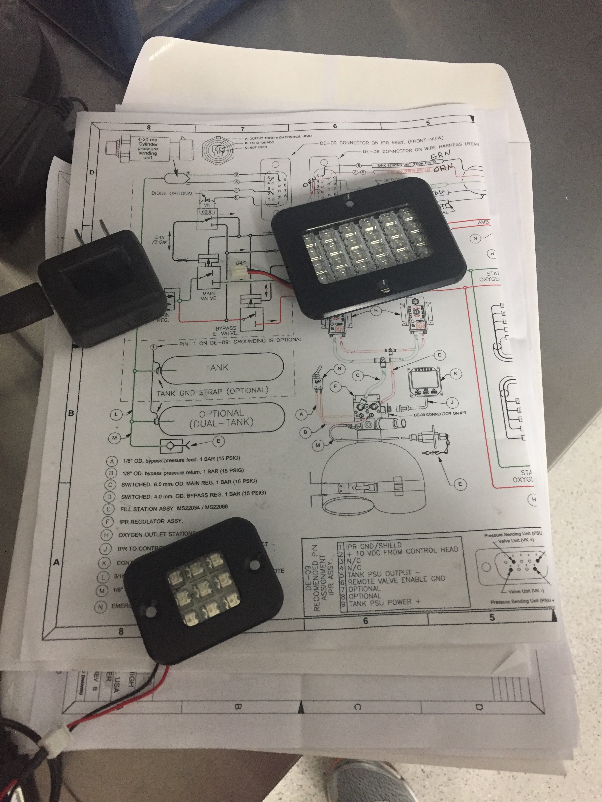
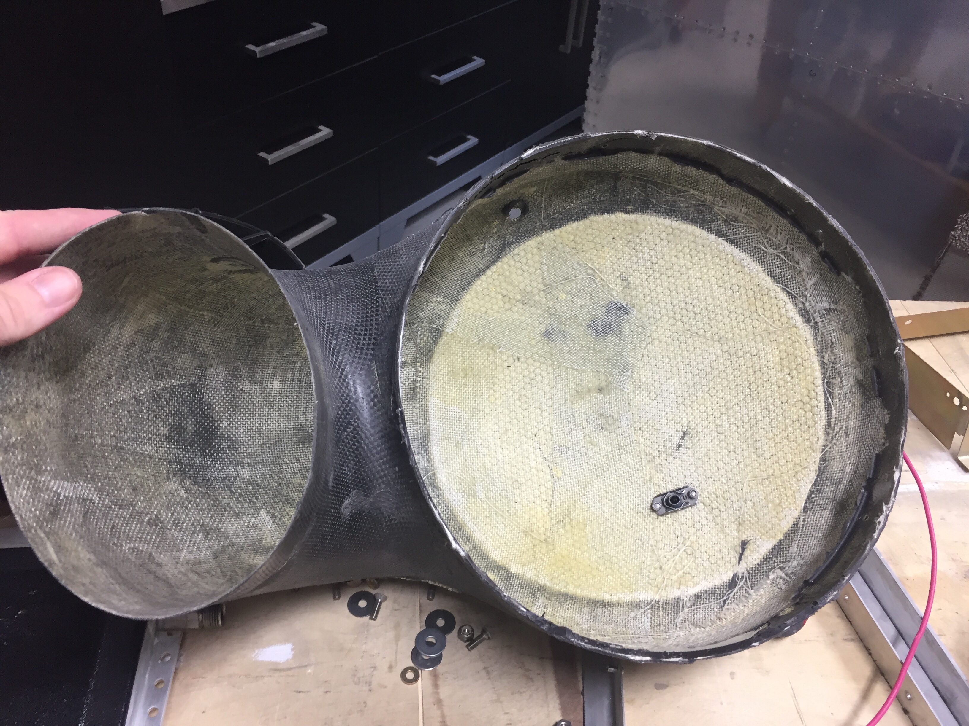
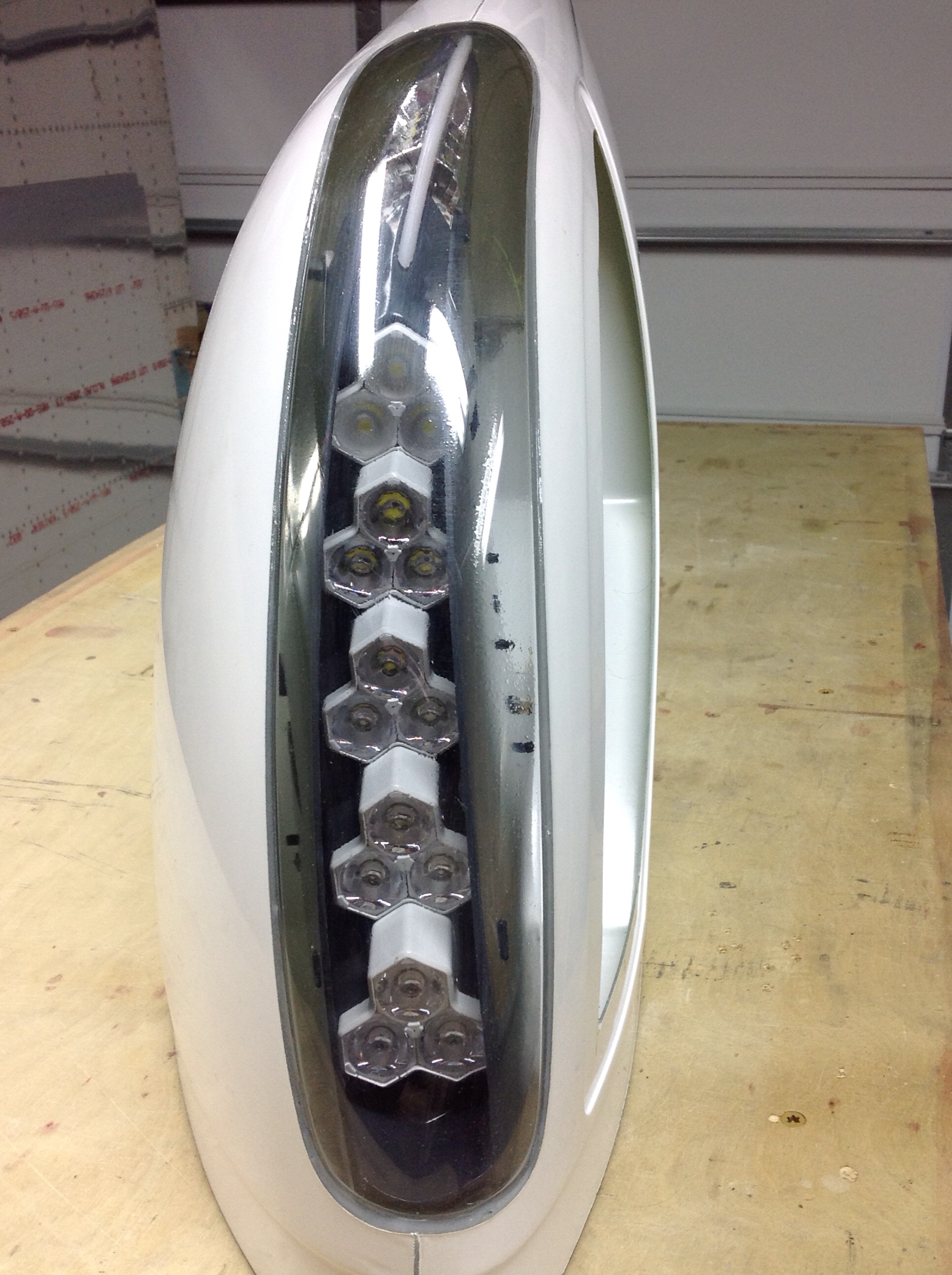
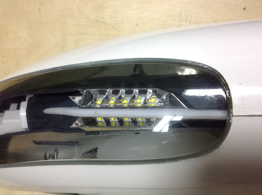
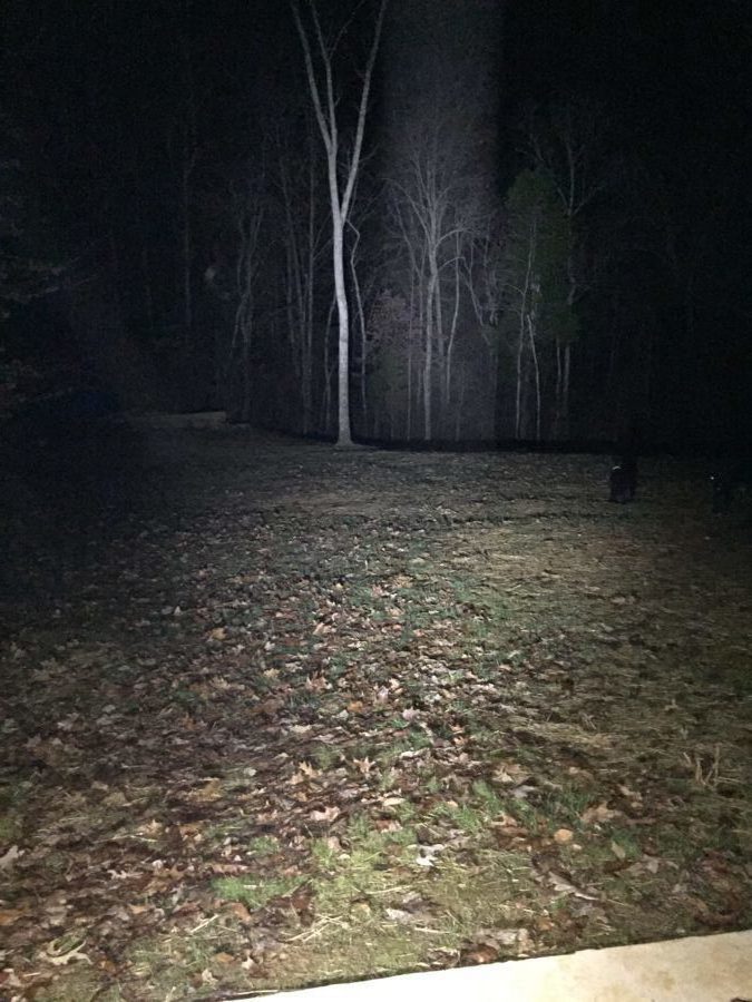
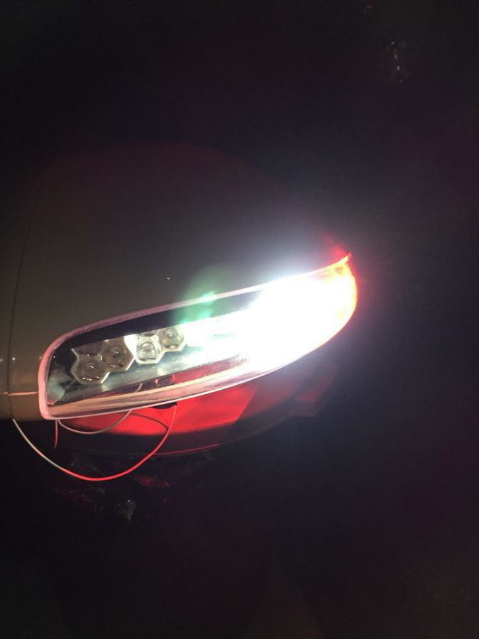
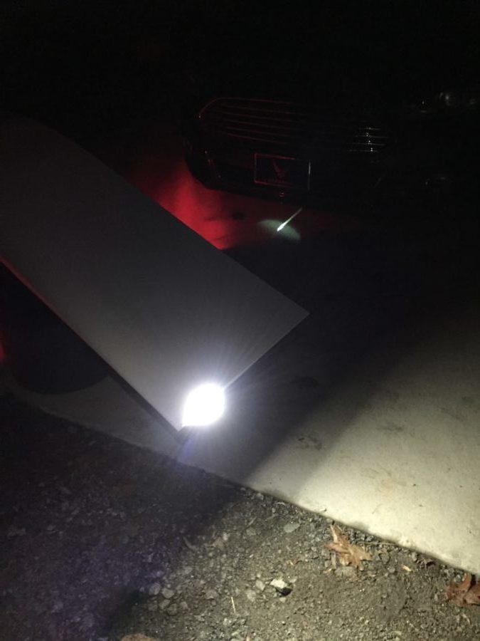
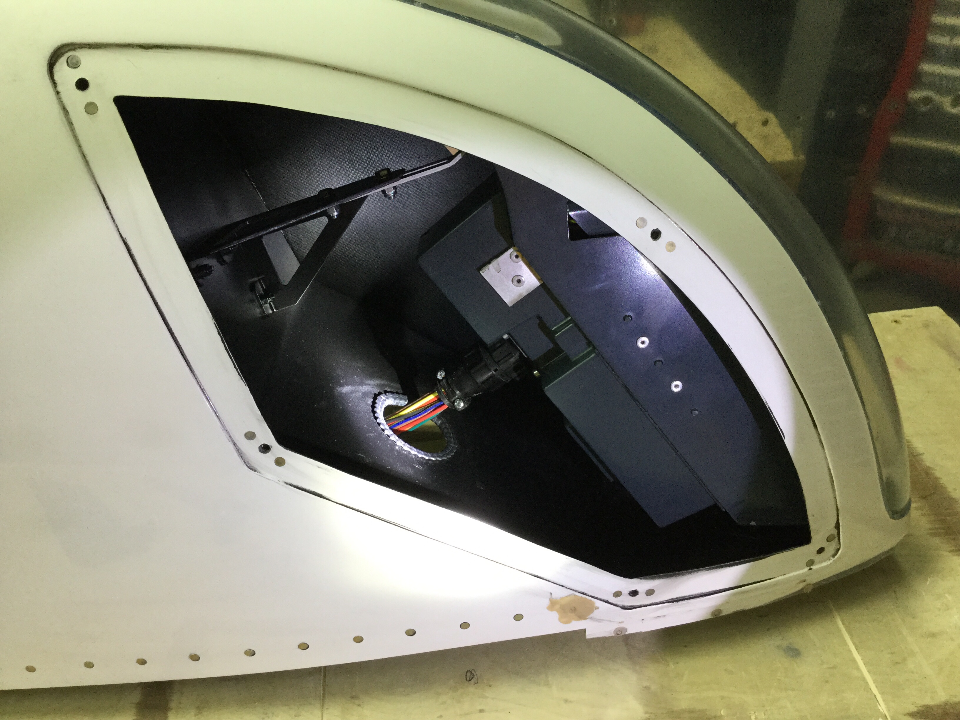
Now, because I was helping out, I received the prototype of the light modules and to say it nicely, they’ve been through a tough time. Unpacking the box, there were a few things rattling around and the back of the light module had come off.

First order of business was to test out the light modules. There is a 16 pin CPC with pigtails included, but the wires weren’t pinned out accurately causing me a few scares that I had shorted out the board or LEDs. After a few emails and testing, I was able to re-pin and document the proper wiring schematic. I did this for both sides and then took the time to re-seal the modules closed using some silicone and fresh hardware.

As others have said, these things are crazy bright! I hooked them up outside just to see what could be lit up and man, I am really impressed. Pictures and video don’t really do justice, but let’s say that I’ve flown many Pipers and Cessnas that have less than half of even one of these landing lights. Combined with the Aerosport taxi light, I think I’ll be able to light up the night just fine.

After testing, I started to do a rough fit and trim, but then they got put to the side waiting on the piano hinges that I planned to use to mount them. A year later, it’s time to finish them up so that I can call the wings complete. The first step was to complete the trim using the methods followed by others to install the tips with hidden piano hinges instead of screws and nut plates. I won’t go into detail as it’s documented on plenty of other build logs and forums out there such as VAF. Taking my time, I was able to get a really nice fit and used the cut off wheel on a die grinder just as I did with the cabin top.

I did run into some interference with the light module mounting hardware that butted up against the end rib. After talking to Van’s support, I drilled an accommodating hole in the rib to allow the hardware to protrude inward through the rib and let the tip sit flush against the skin. Once I had the hinges on, I split the trailing edge to reposition and line up with the ailerons. This is a common practice, even on the stock tips and was fairly straightforward. After a bit of work, I had a nice straight line from flap to tip.

Finally, I received some stainless steel hardware in for the light module access covers and mounted them with nutplates. Others have used a lot more fasteners than I did, and I’ll probably go back and add a few more before first flight. I painted the inside of the light area black to give the lights a meaner and cleaner look. I also painted the outside of the light reflectors, again, just for cosmetic purposes. Next up will be to run the wiring through the wings, mount the archer antenna, and make a pin retainer for the hinges.

Removing museum pieces

Parish came over for a pizza dinner with the wives and we managed to extract a museum piece off the ceiling.  The big pink thing that folks have asked about for the past three years is finally part of the airplane!  With his help, I did the initial trimming of the door frame and longeron area using the cut off wheel on the die grinder.  While it did produce some dust, we were outside and it really wasn’t a bad process. The scribe lines were pretty accurate where they were visible, but there were quite a few places the line was way off or missing all together.

I initially trimmed the side skirts and door frame area just to get it on the fuselage. I had to take it on and off a few times and looking back, I wish I had thought out the process a bit better. You could measure the frame and make your own marks then do a final trimming. Fortunately, the top is mounted in a bed of flox so other than some sanding and contouring, it will be fine to have some gaps such as mine around the frame.

I had considered doing an overhead pulley system since I knew it’d come on and off, but really it’s not too heavy and I’ve found a good system of crawling inside and lifting the top up with my shoulders. Then I can put it on the seat rail and spar while I get out of the plane to lift it through the door frame onto the table. All in all I think I took it off about 10 times before it was all trimmed up.

It’s really cool to see all of this together. The thing actually looks more like a plane (or at least more of a plane) than it ever has. The back seats are really roomy! Next up is trimming the window openings, door flange, and windscreen flange.