Back that light up

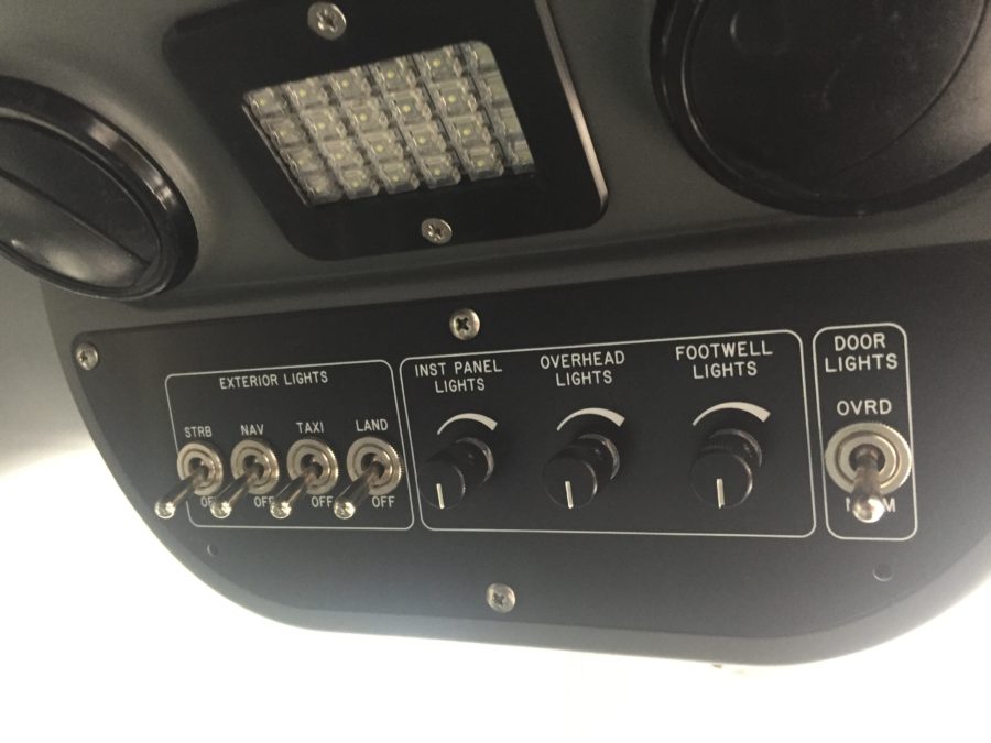
One of my most exciting side projects on the plane is to have a truly unique instrument panel.  From the start, I have wanted a back light system similar to fancier aircraft out there and to pretty much every car out there.  Glareshield lighting, post lights, or dome lights just don’t work or look the same, so I wanted something better.  Ed Krantz did a great job using LED strip lighting but had to do a lot of work to get it working.

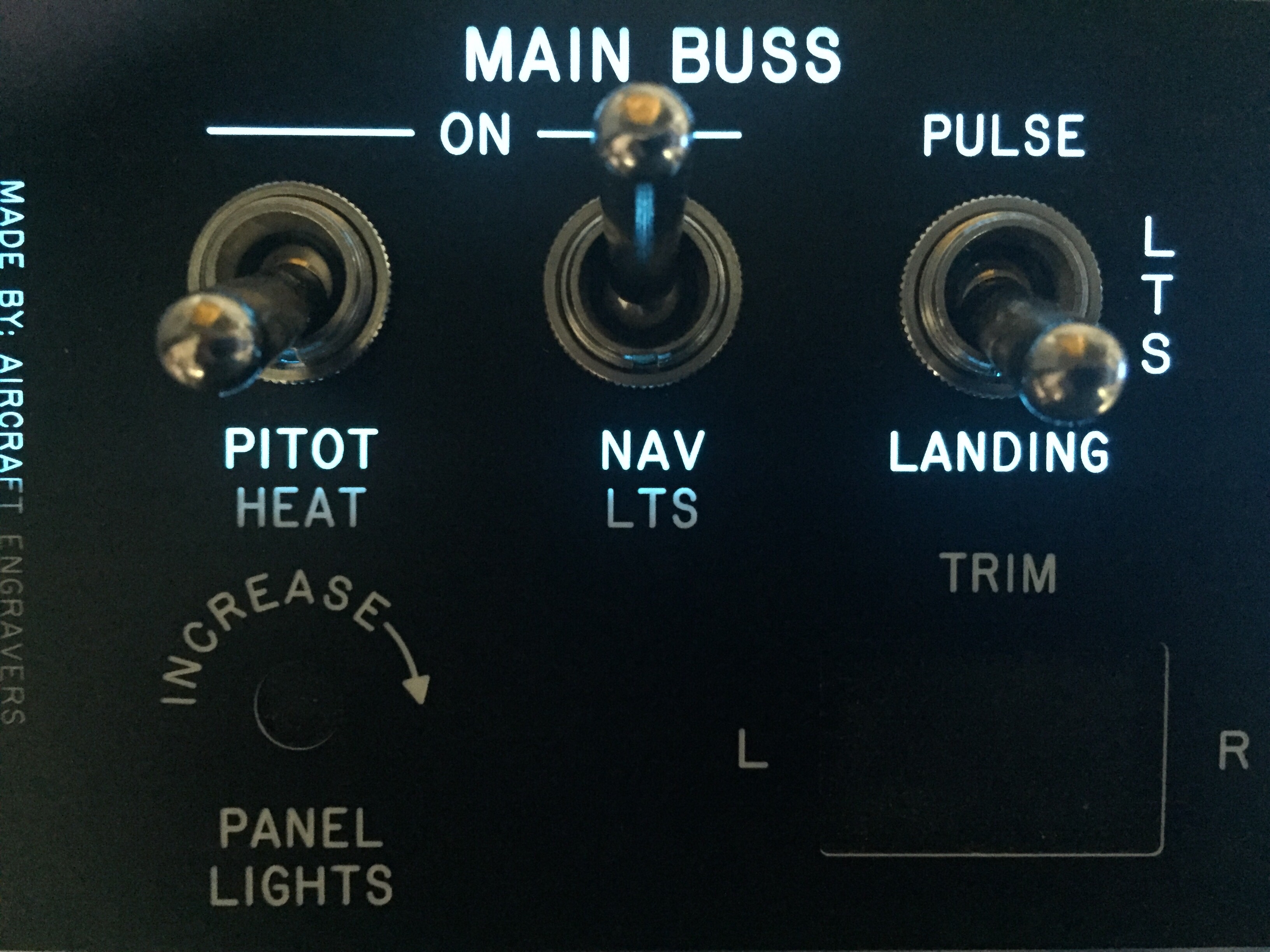
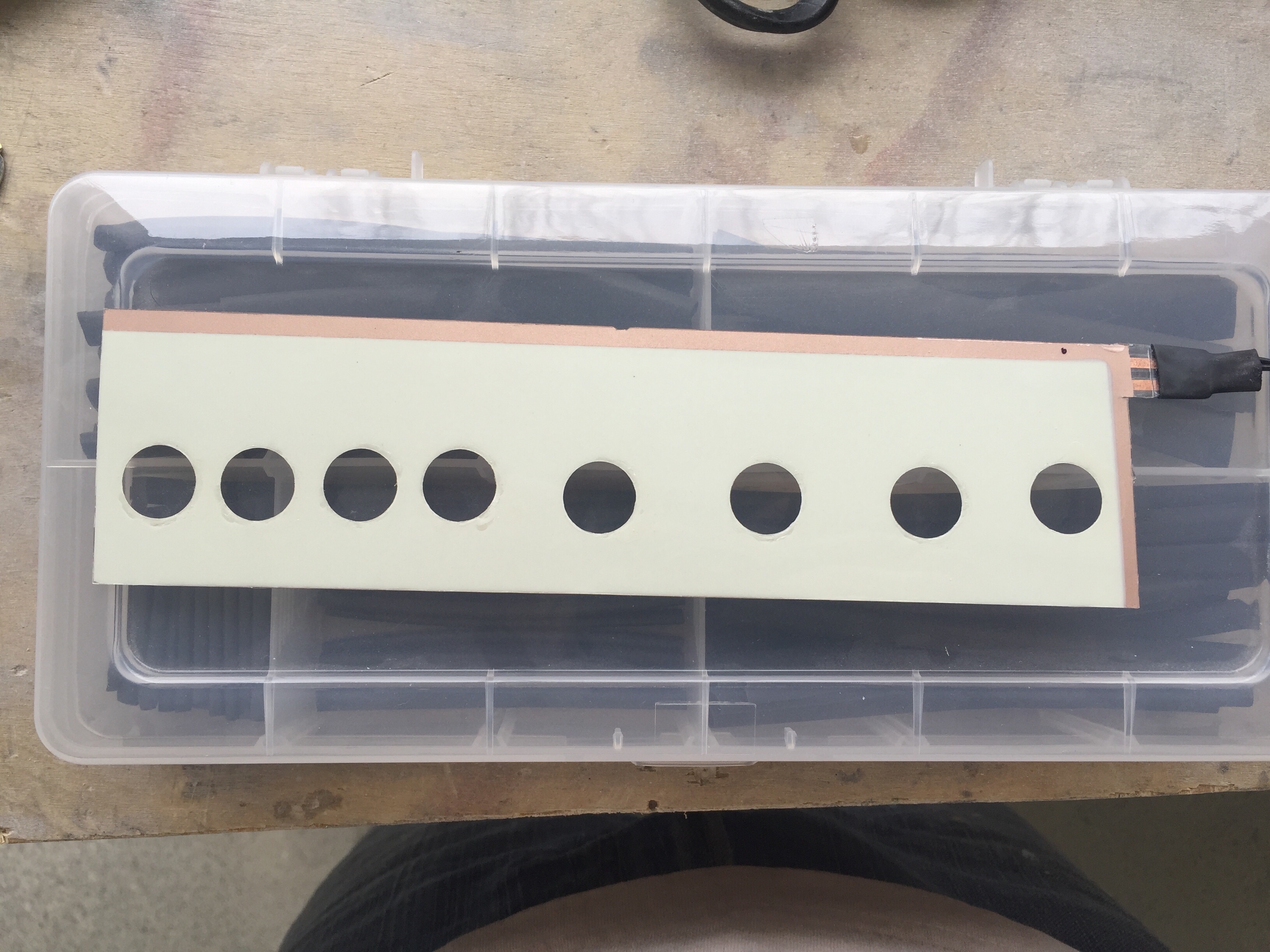
As briefly discussed in THE ART OF DESIGN, I decided to experiment with electroluminecent panels.  These EL panels are almost paper thin, flexible, and can be cut in all sorts of shapes.  Better yet, they are dimmable and have a uniform light output.  After a successful prototype on the overhead console panel, I pulled the trigger and ordered the full layout of the EL panels and the laser engraved acrylic overlays.

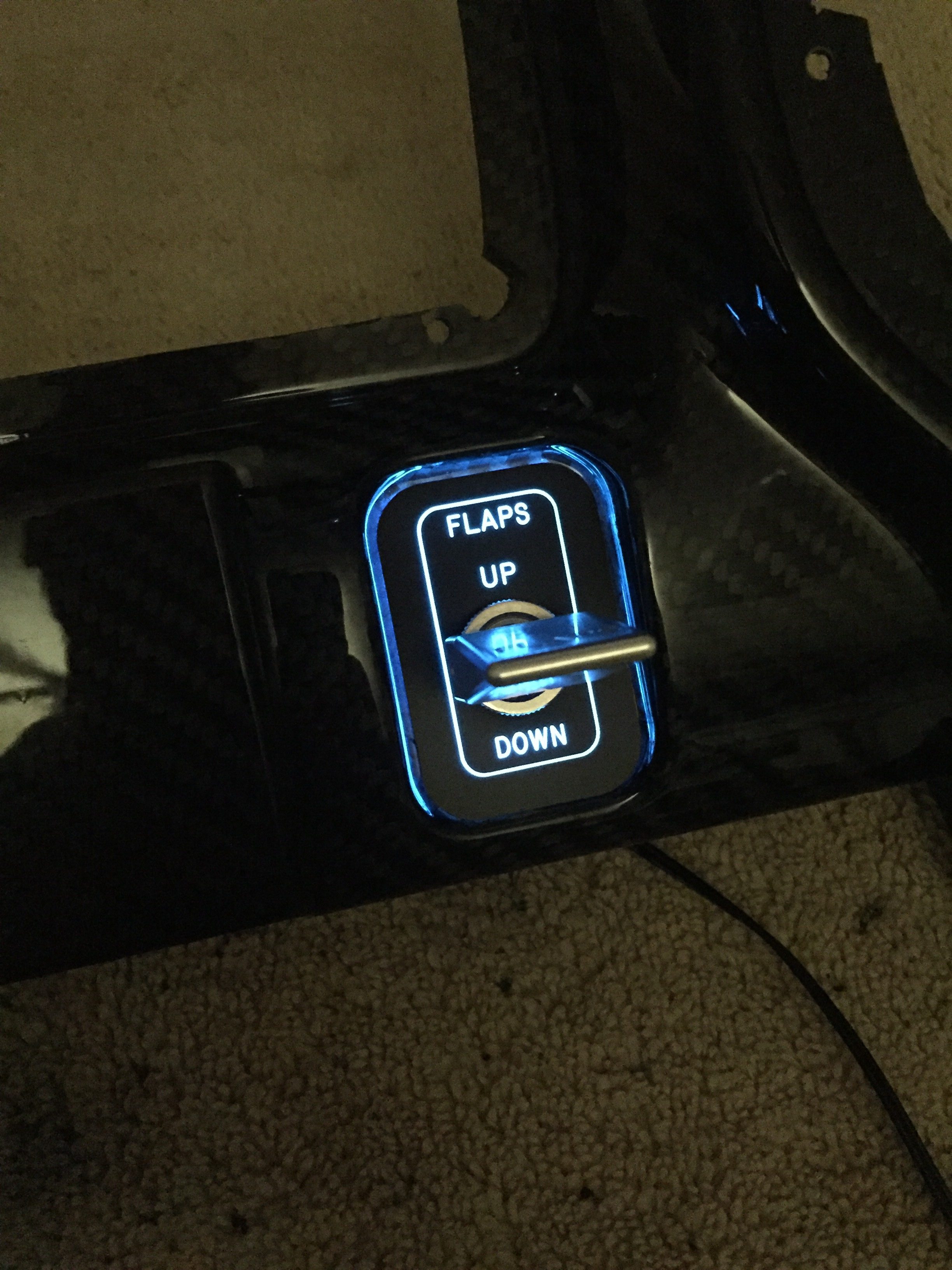
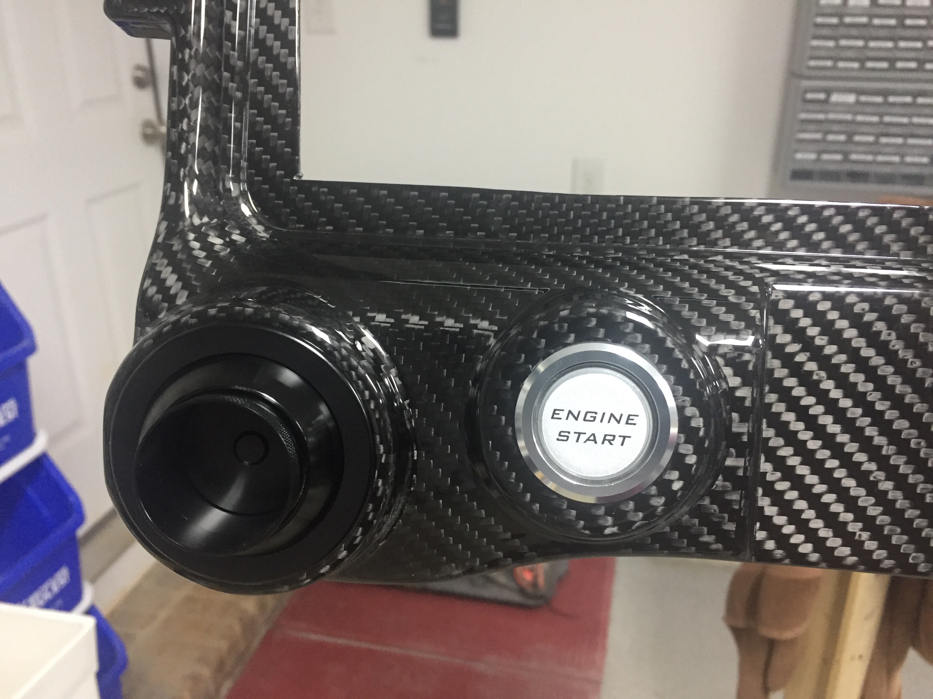
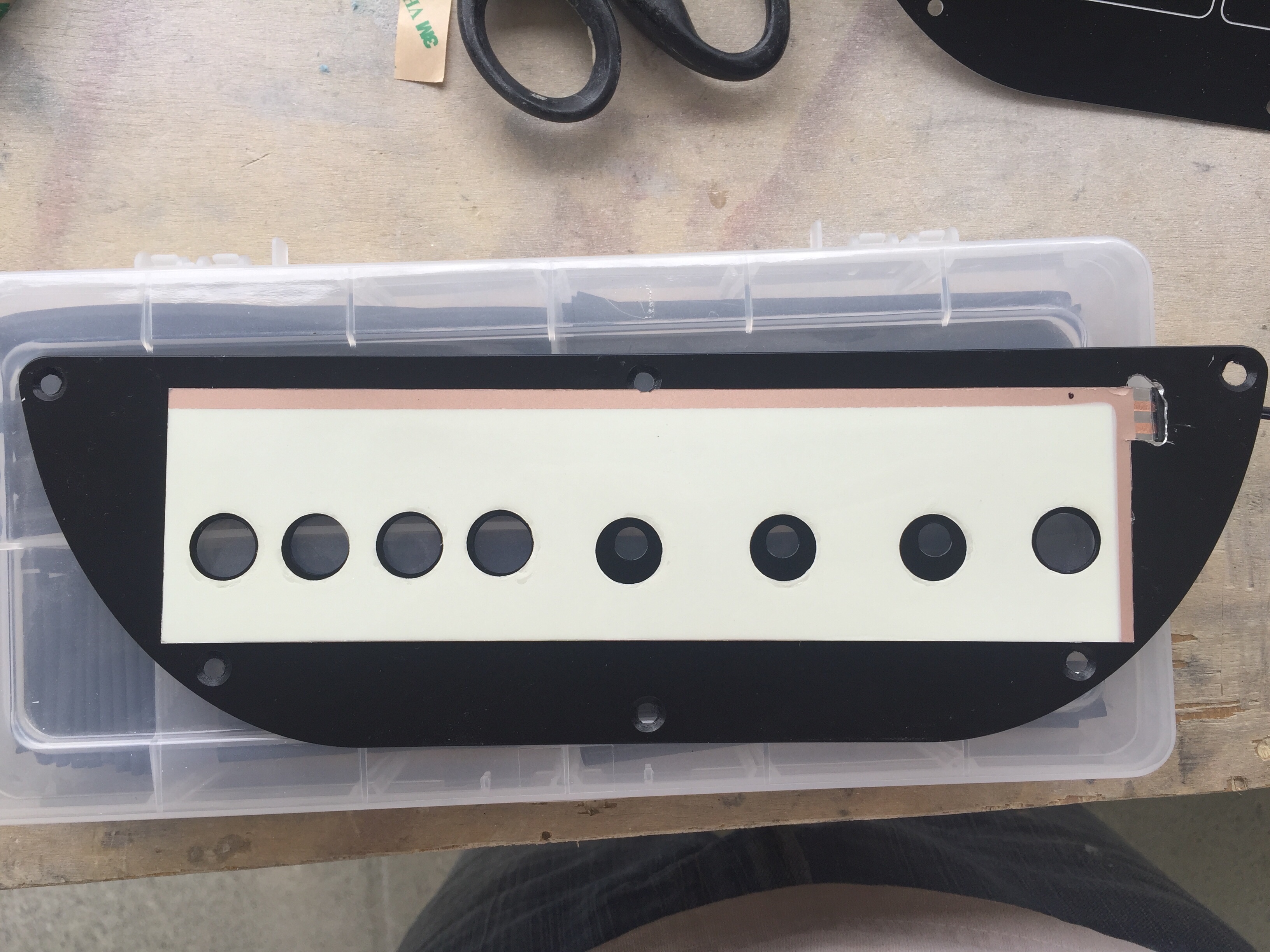
The EL panels came from Marc at Lightkraft via Etsy.  Marc was phenomenal to work with and took a personal interest in the project.  We had to iron out some dirty details on orientation, power leads, size constraints, etc.  I wound up taking his limfacs and finessing the panel layout a bit around the EL panels to make sure everything lit up as desired.  I also had to be strategic on where the power leads would be located along with the two edges that are unlit where the leads run.  On those two sides, it’s about 3/16″ that is unlit and cannot be cut, so positioning those correctly was key.  The other two edges could be cut and shaped in any way needed.  Finally, holes in pretty much any shape can be cut out of the middle to allow for switches or components without affecting the rest of the EL panel.  On any cut edge, the panel must be sealed to prevent oxygen from ruining the EL material.  Marc suggested clear acrylic nail polish which was easy and quick.  The prototype was done in white, but I wanted the final product in all blue.  Marc did a great job taking the 1:1 sized PDF I produced from my CAD design and producing the panels.  He provided a transformer based on the total surface area of the panels so all will be wired together and be on one dimmer.

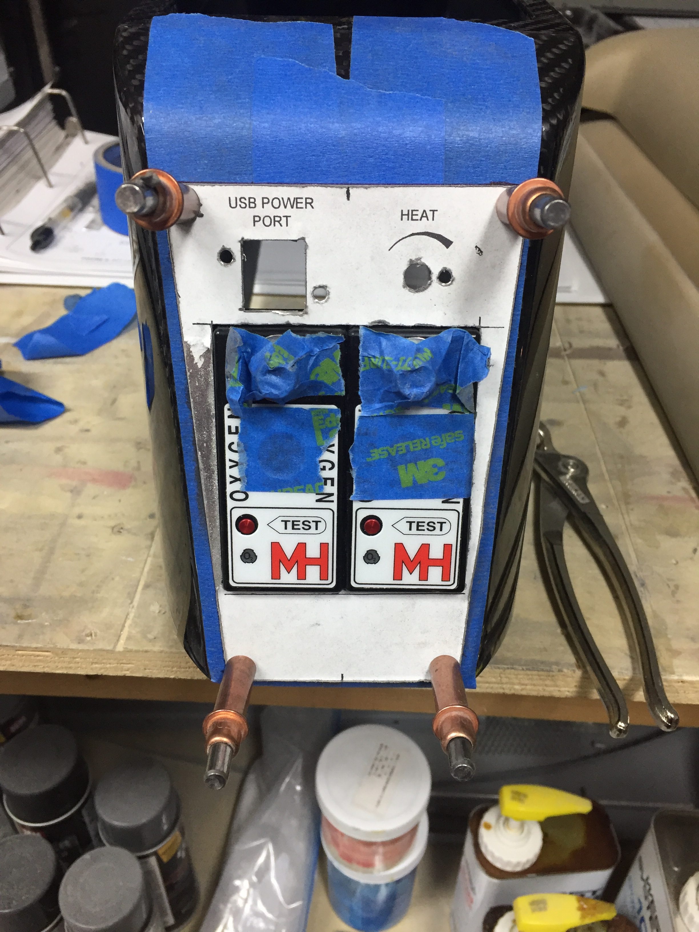
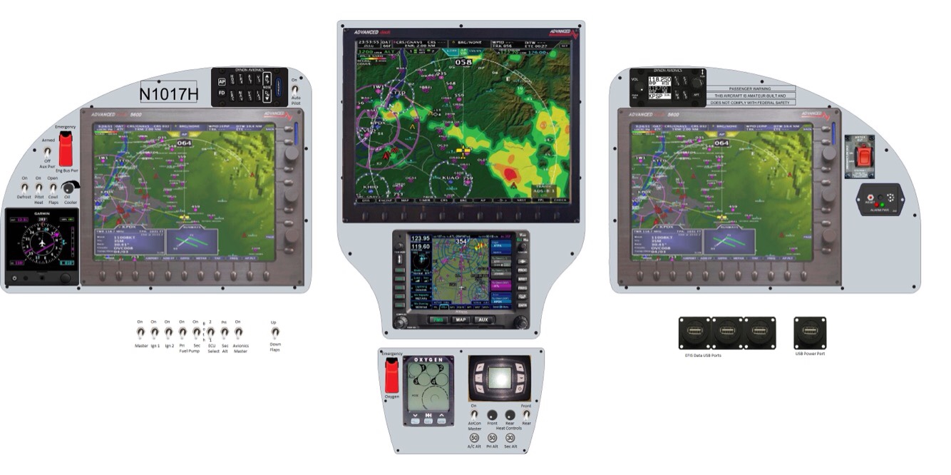
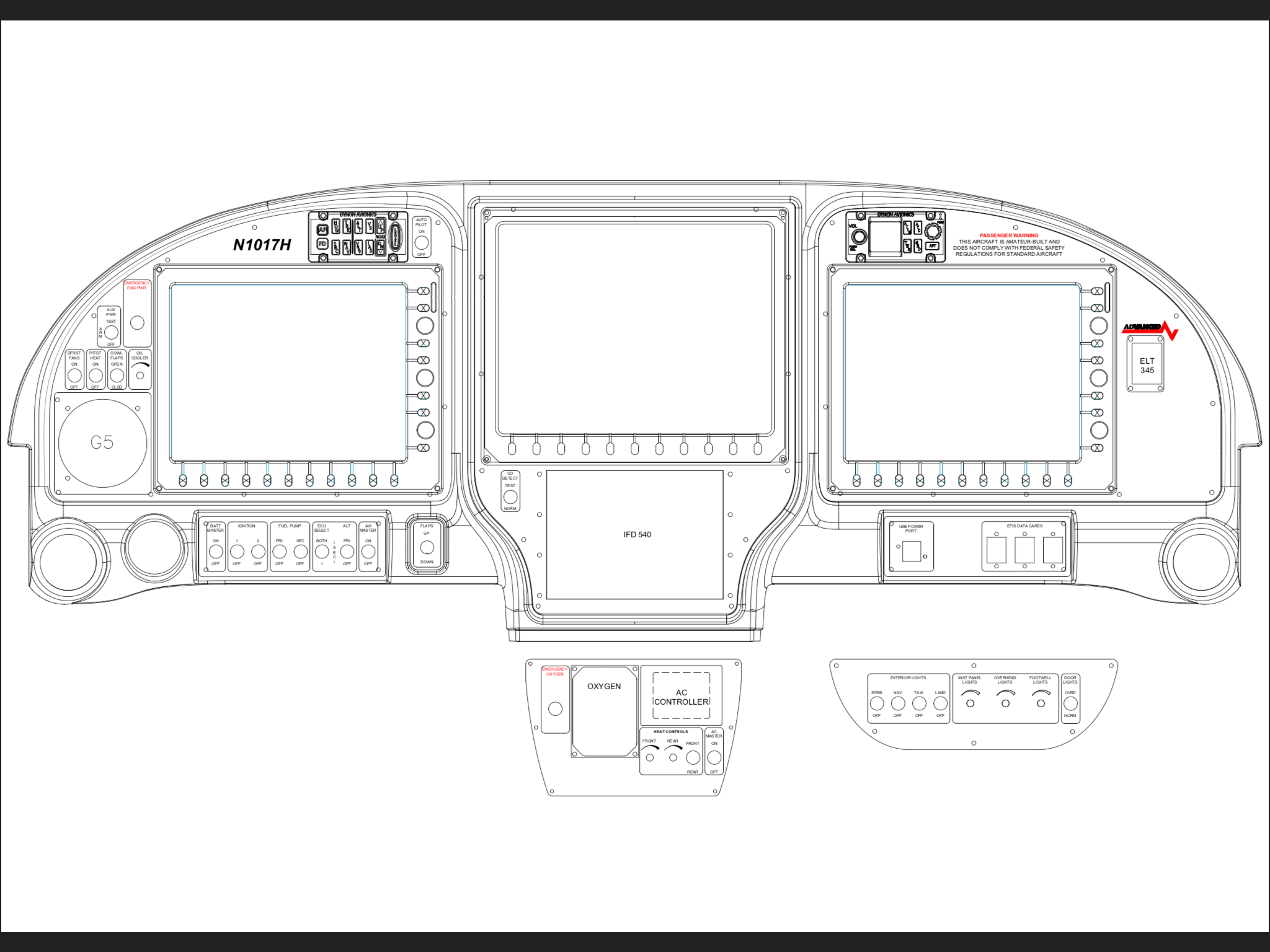
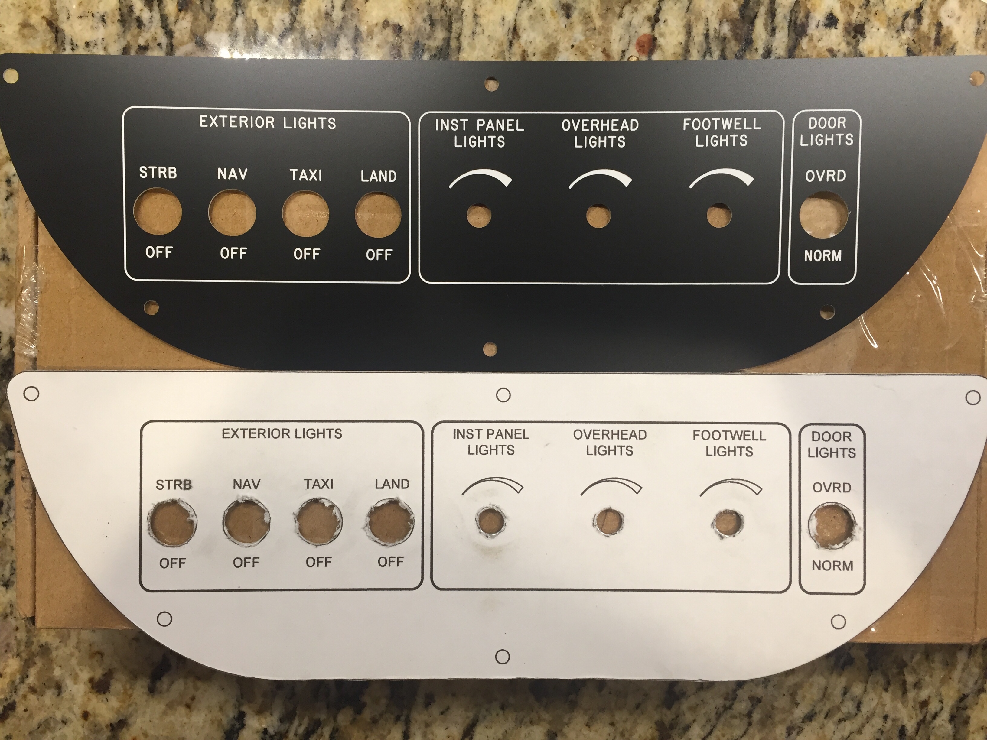
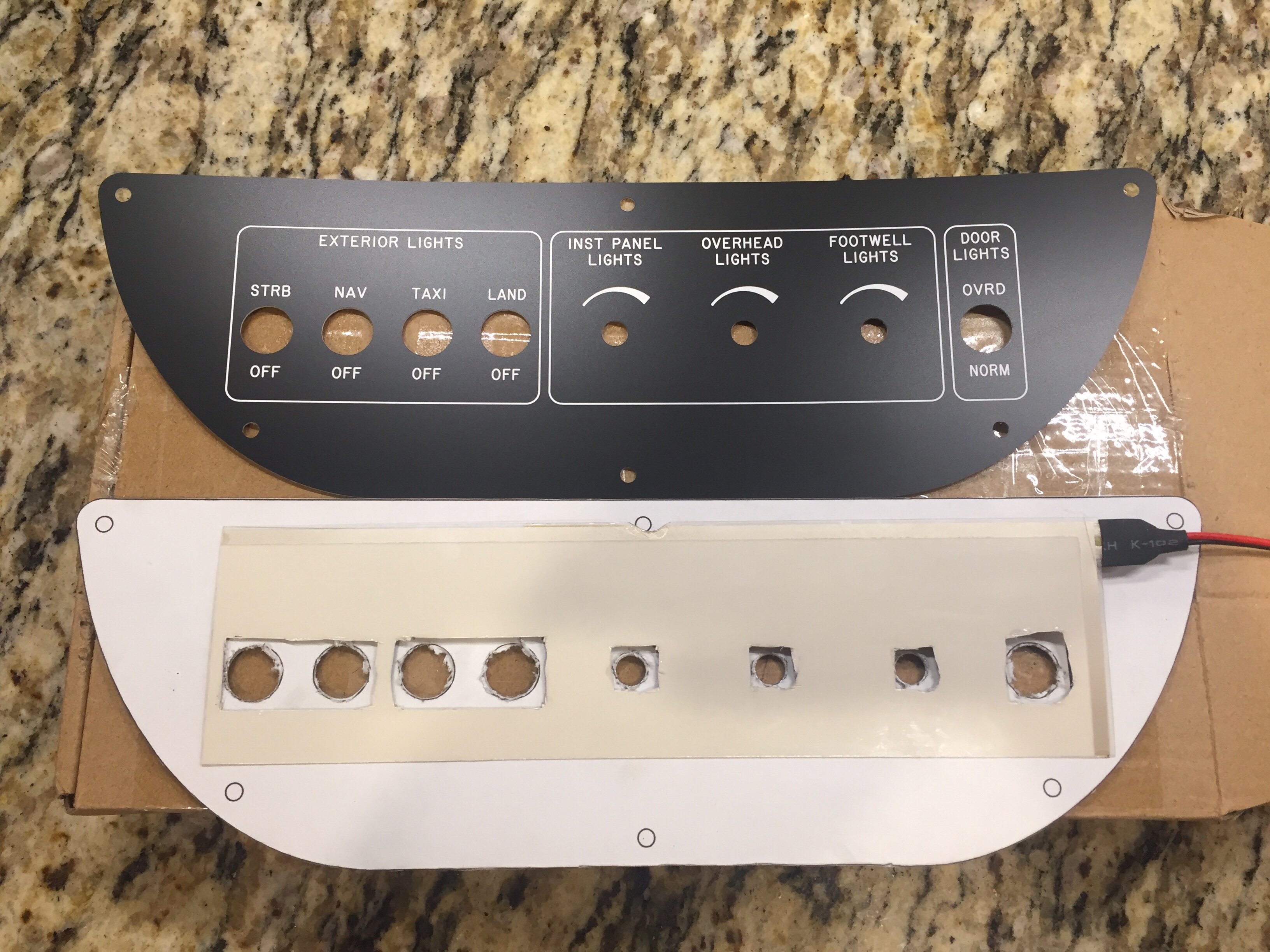
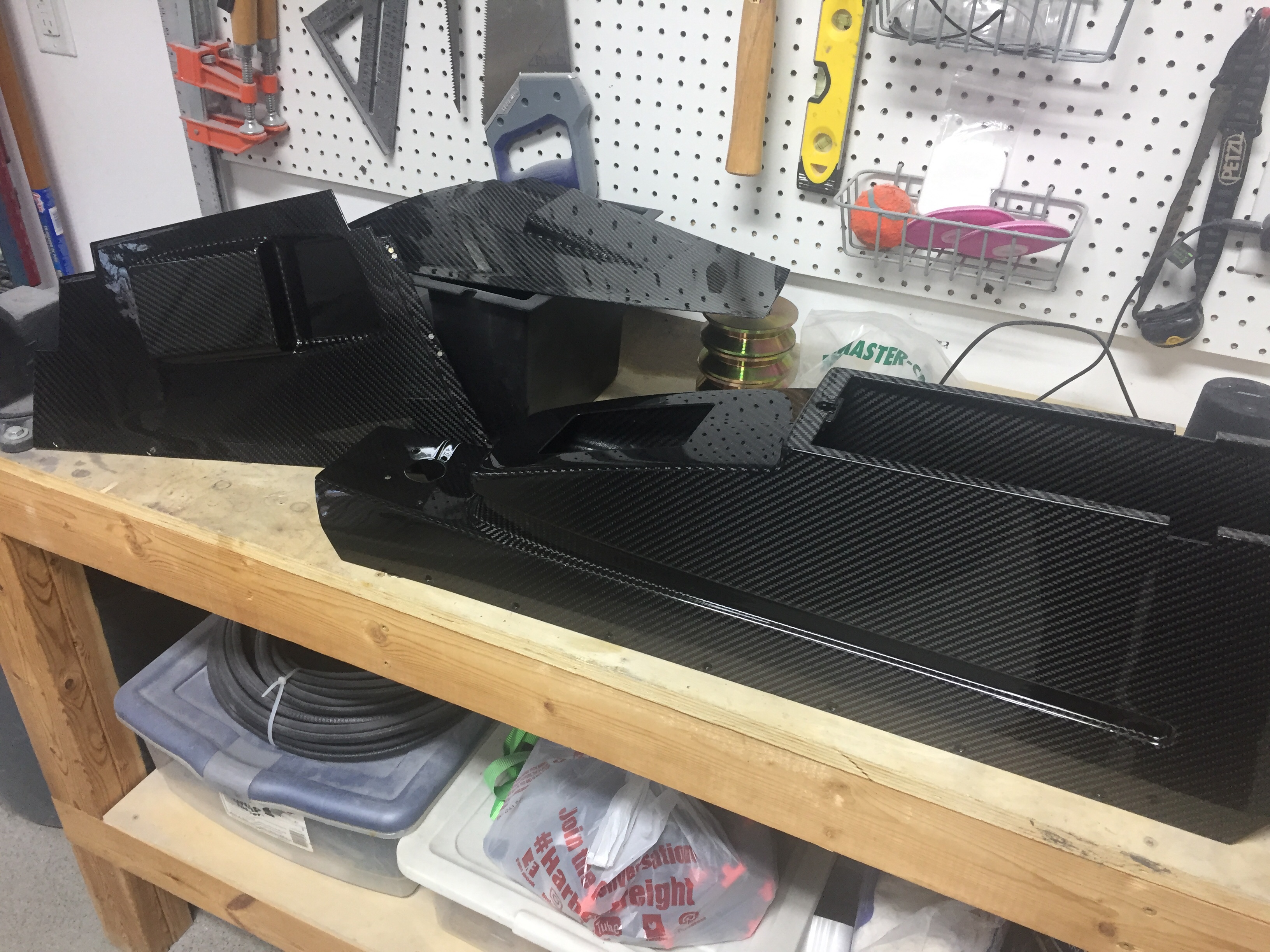
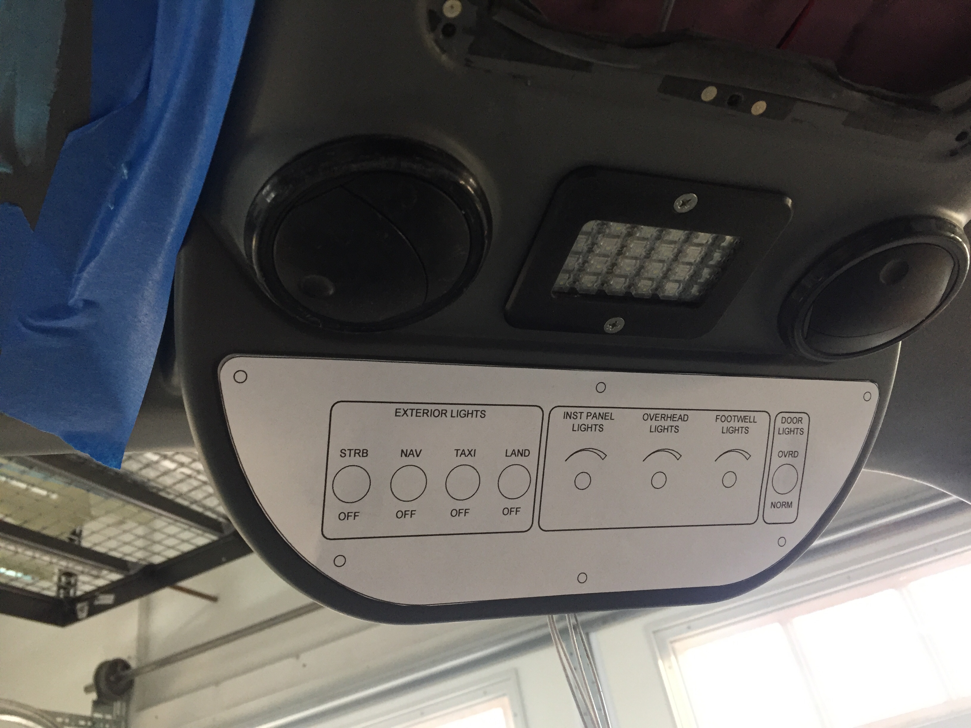
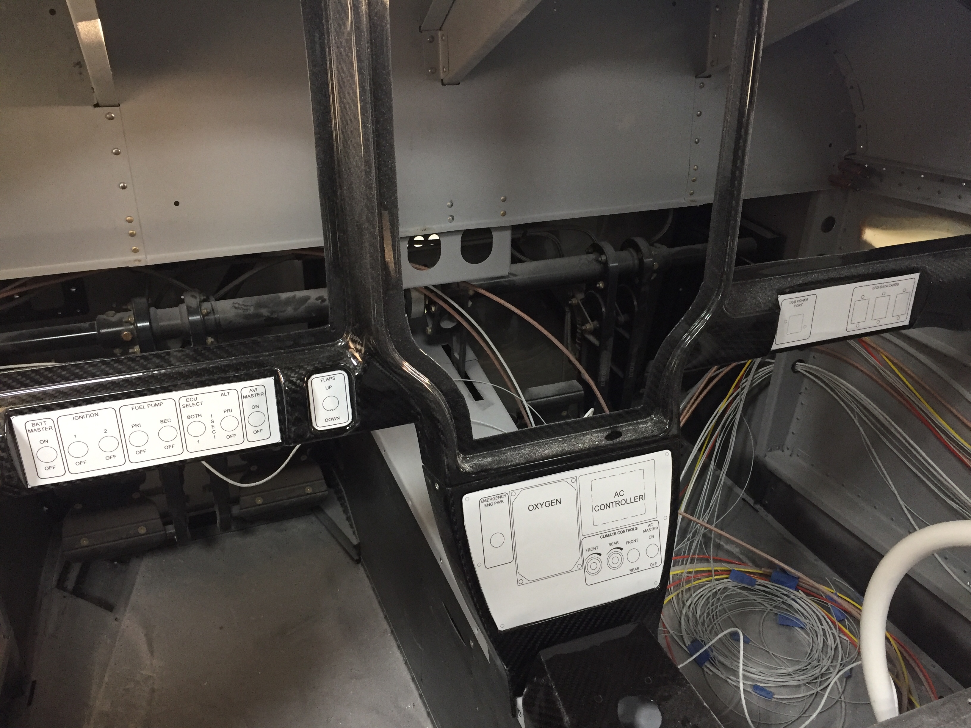
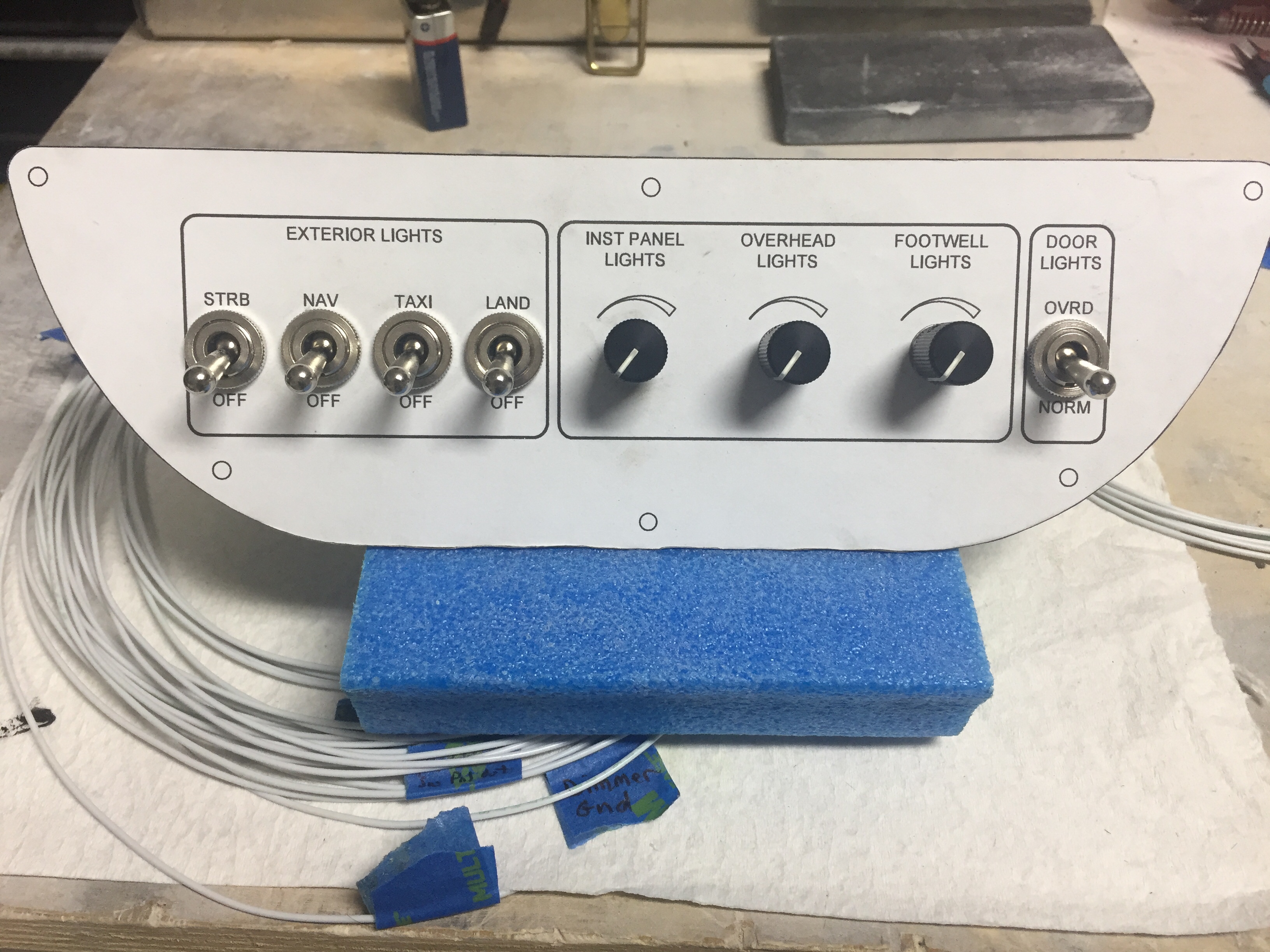
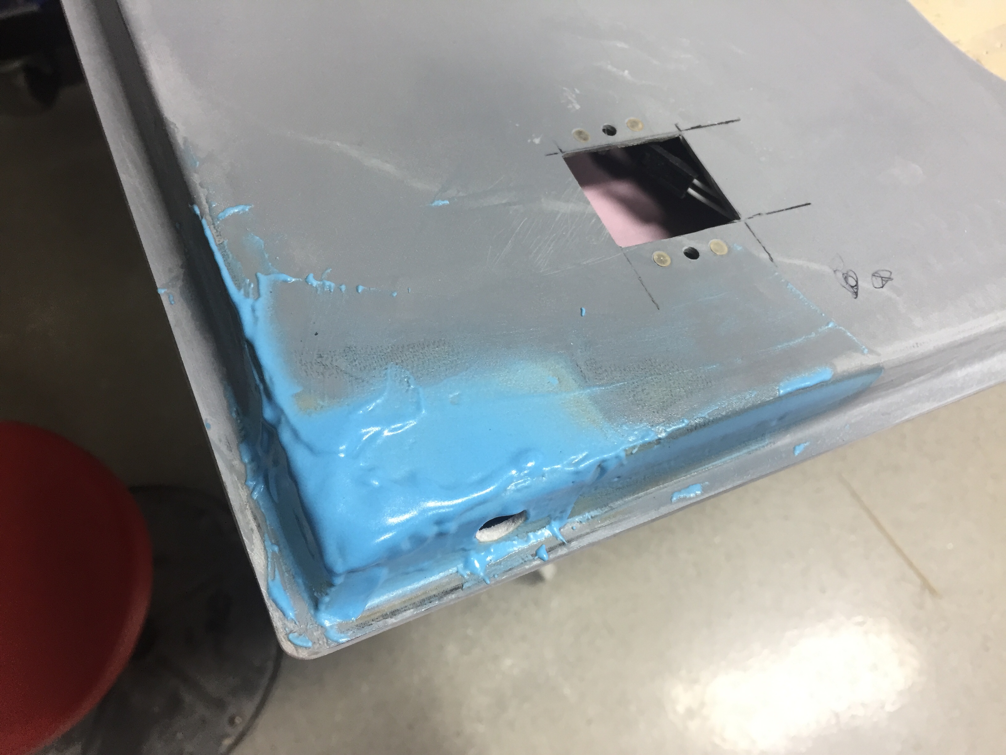
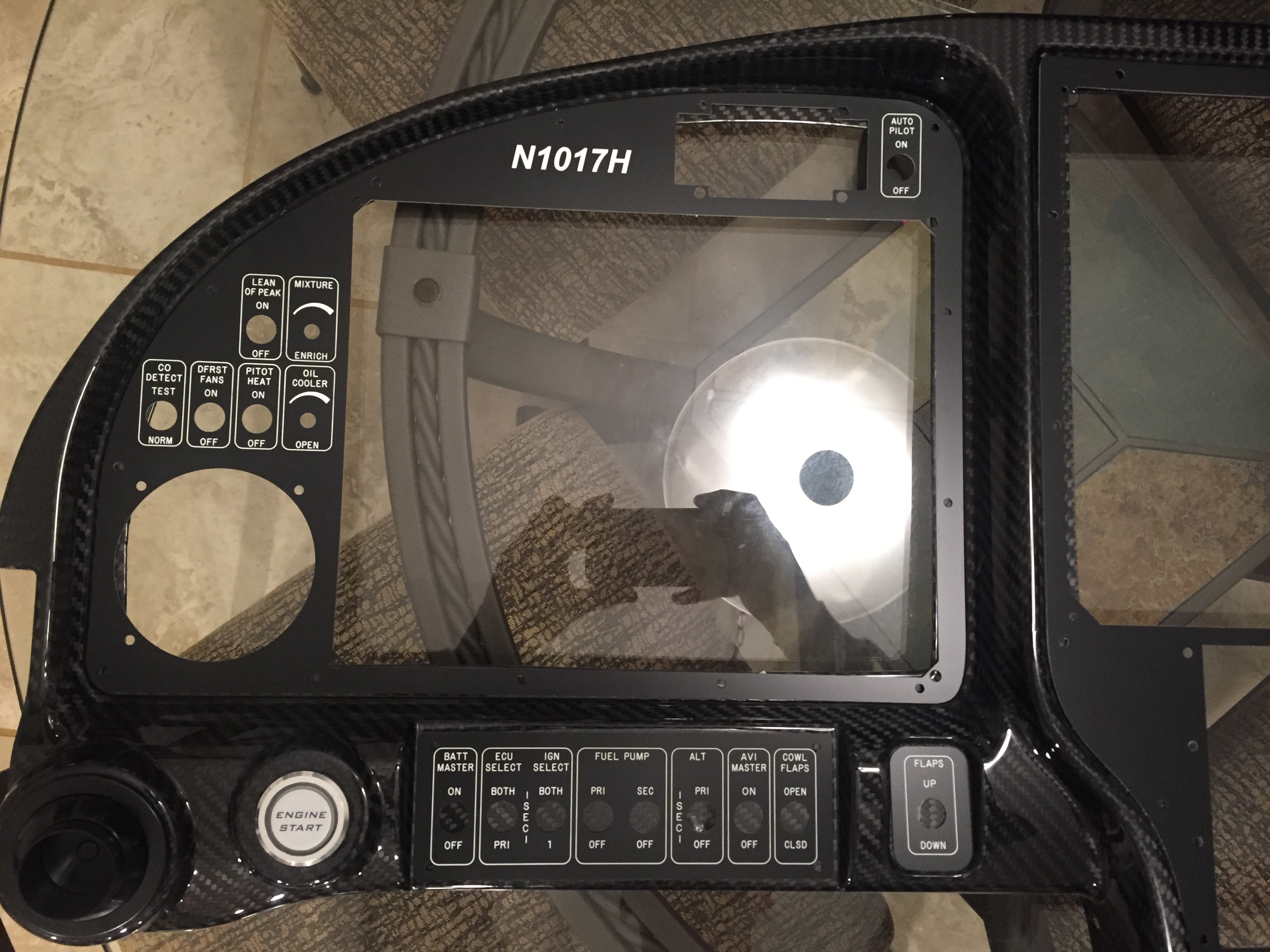
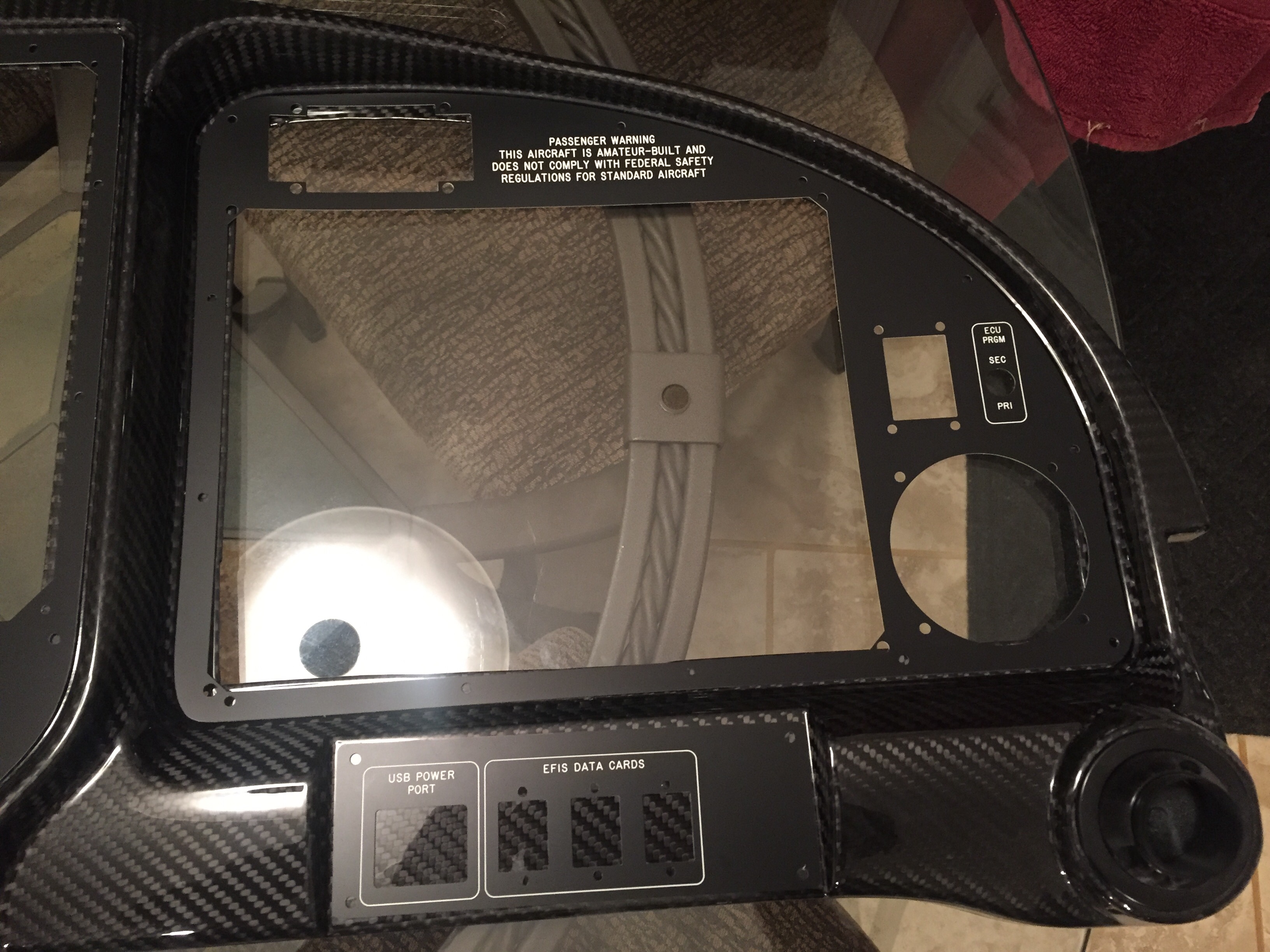
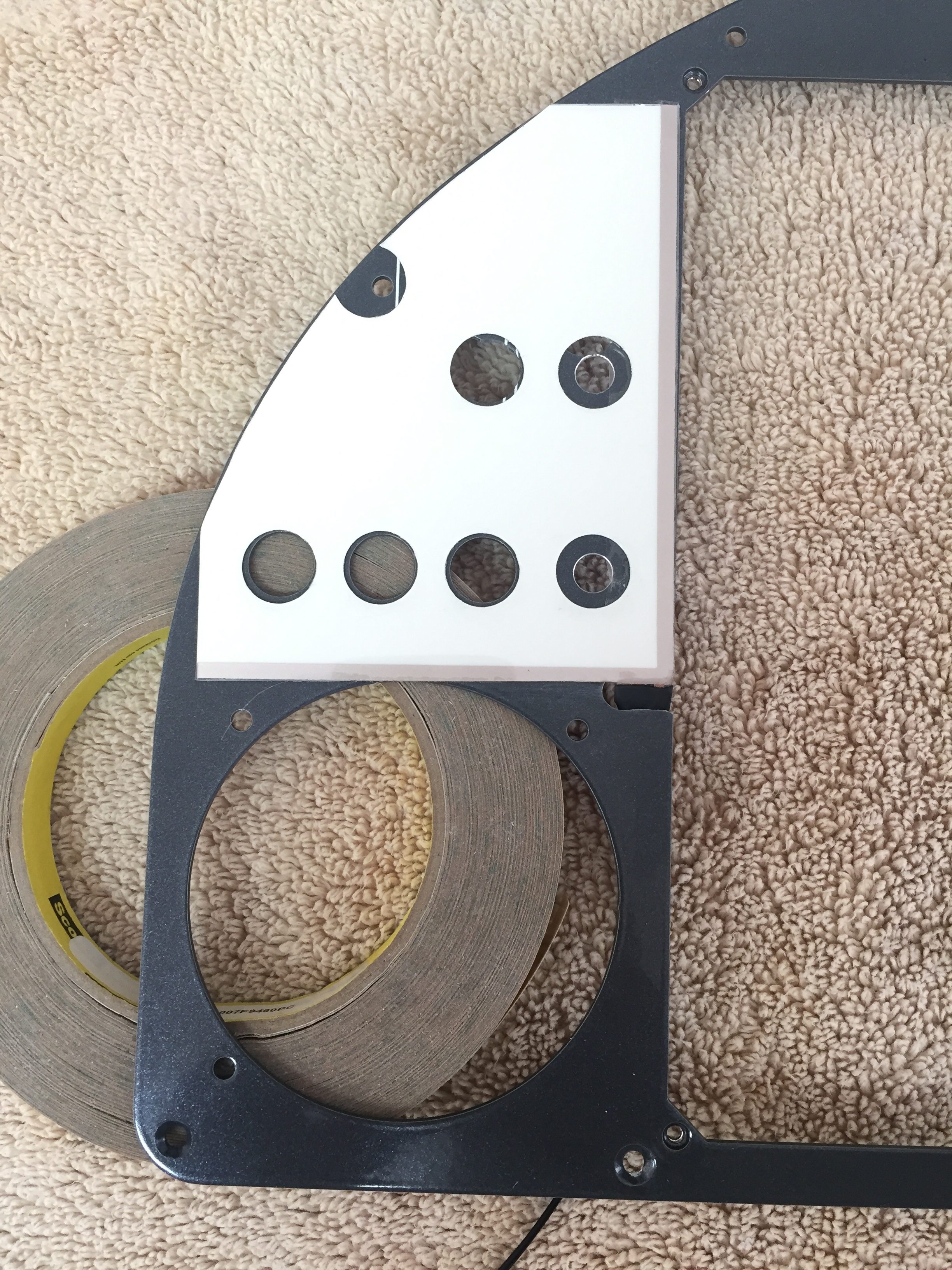
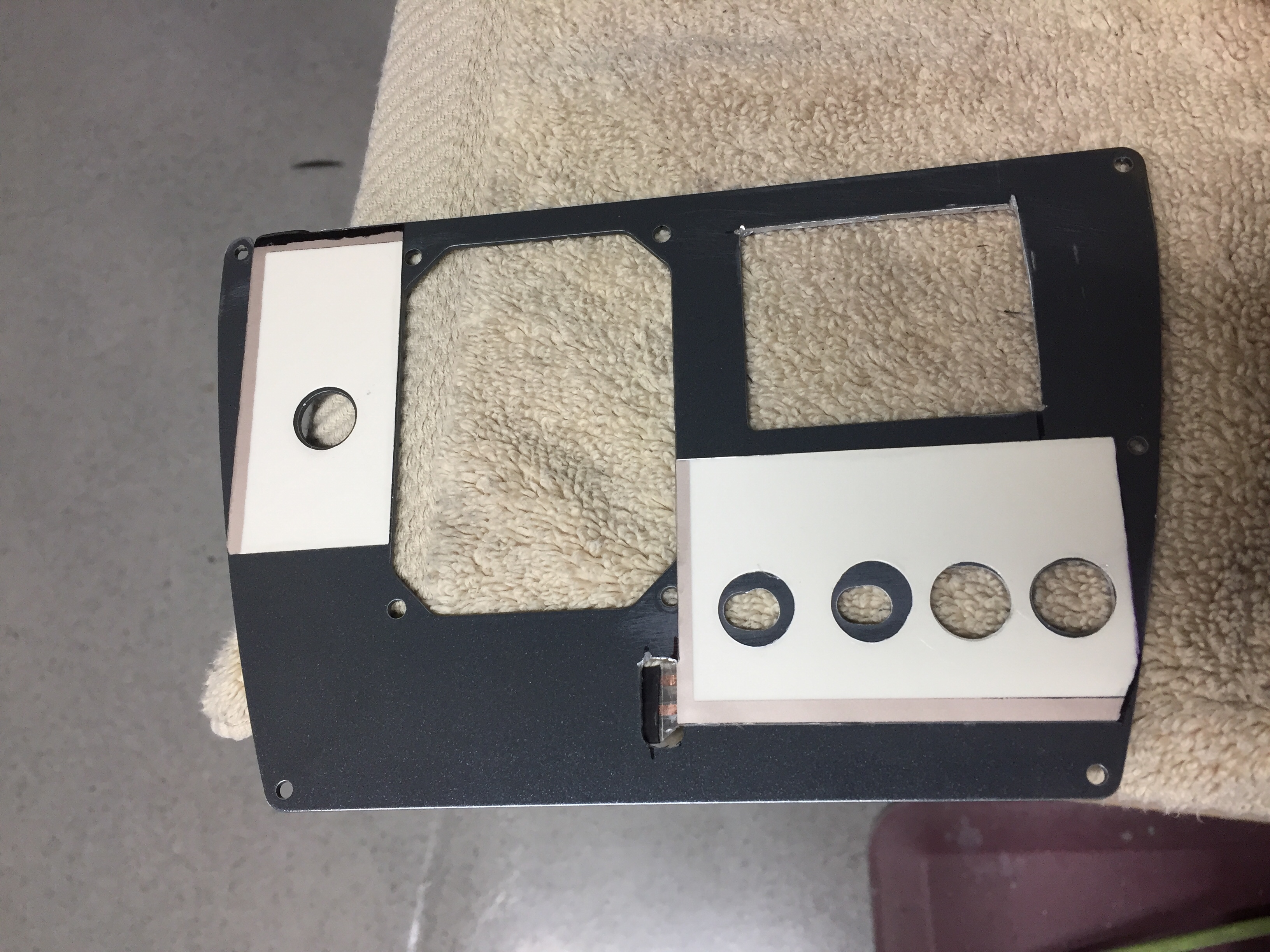
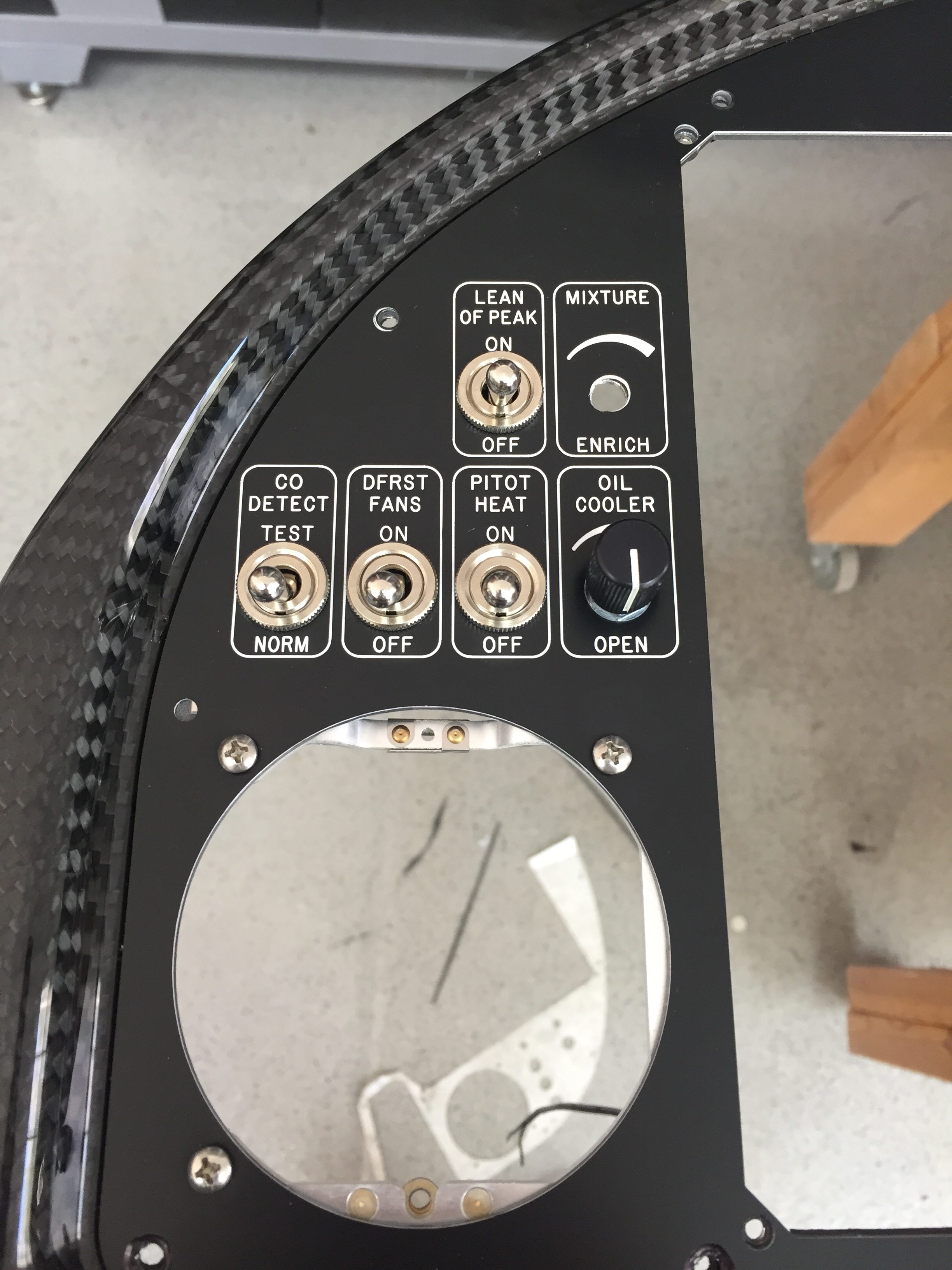
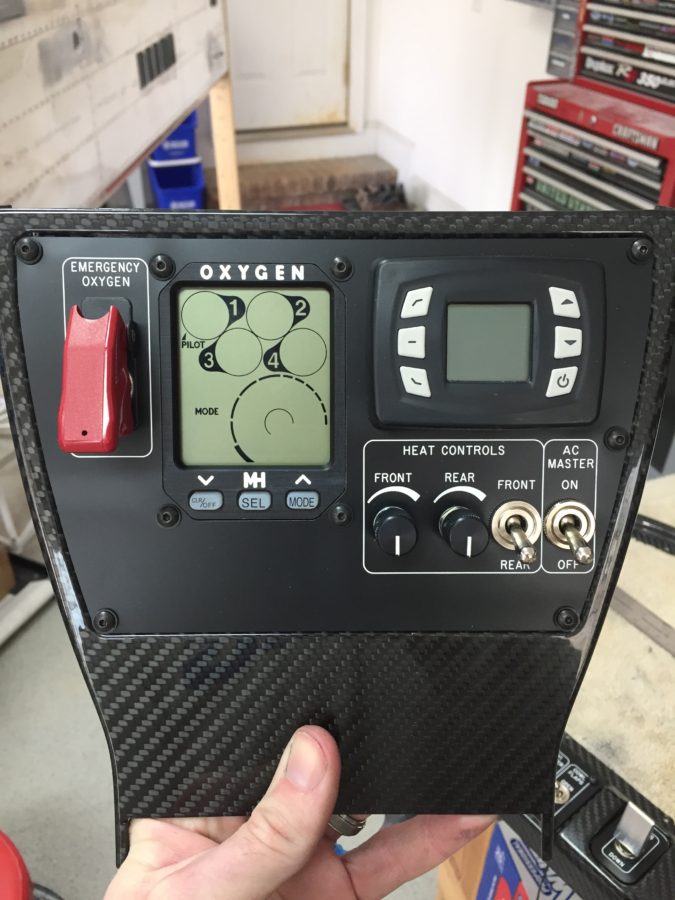
Since AFS helped design and is producing a quick panel for me, the metal inserts for the four major sections of the Aerosport 310 panel are being cut and silk screened by AFS.  I wanted that as a back up to the EL panels just in case those didn’t work out or fail and are not replaceable sometime down the road.  After finalizing the design with Stephan at AFS, I sent the same CAD design to Matthew at Aircraft Engravers and requested all the panels be cut from black on white acrylic, just the same as the overhead console test panel.  Matthew was able to cut all component, switch, and screw holes then laser engrave all of the markings.  The acrylic panels have a self sticking backing so applying them for good is as simple as pulling off the backing and sticking them on the metal panel!

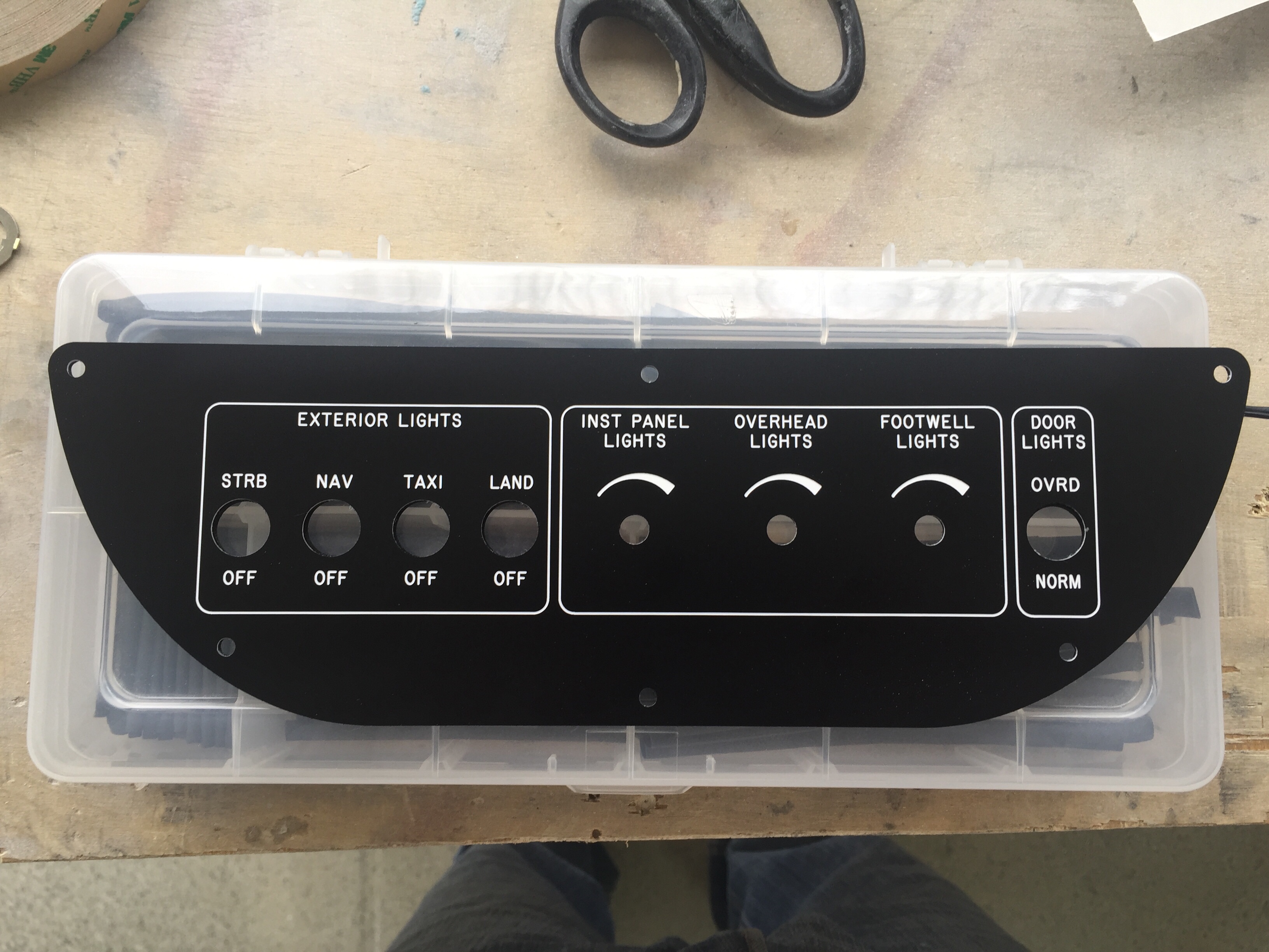
I took some time to ensure each EL panel fit the area needing back light and trimmed a few spots to clean it up.  I used a 5/8″ punch to punch holes for switches and dimmers in the EL panels.  The idea was to avoid the EL panel contacting any metal avoiding shorting and any interference noise the panels may translate to the air frame.  From what I can tell, neither is necessary as metal doesn’t seem to bother the EL panel and test flying the prototype in the Diamond yielded quiet radios and headsets.  After all of the holes were cut and trimming was completed, I turned into a little kid and played with everything in the dark to make sure all engraving was properly lit.

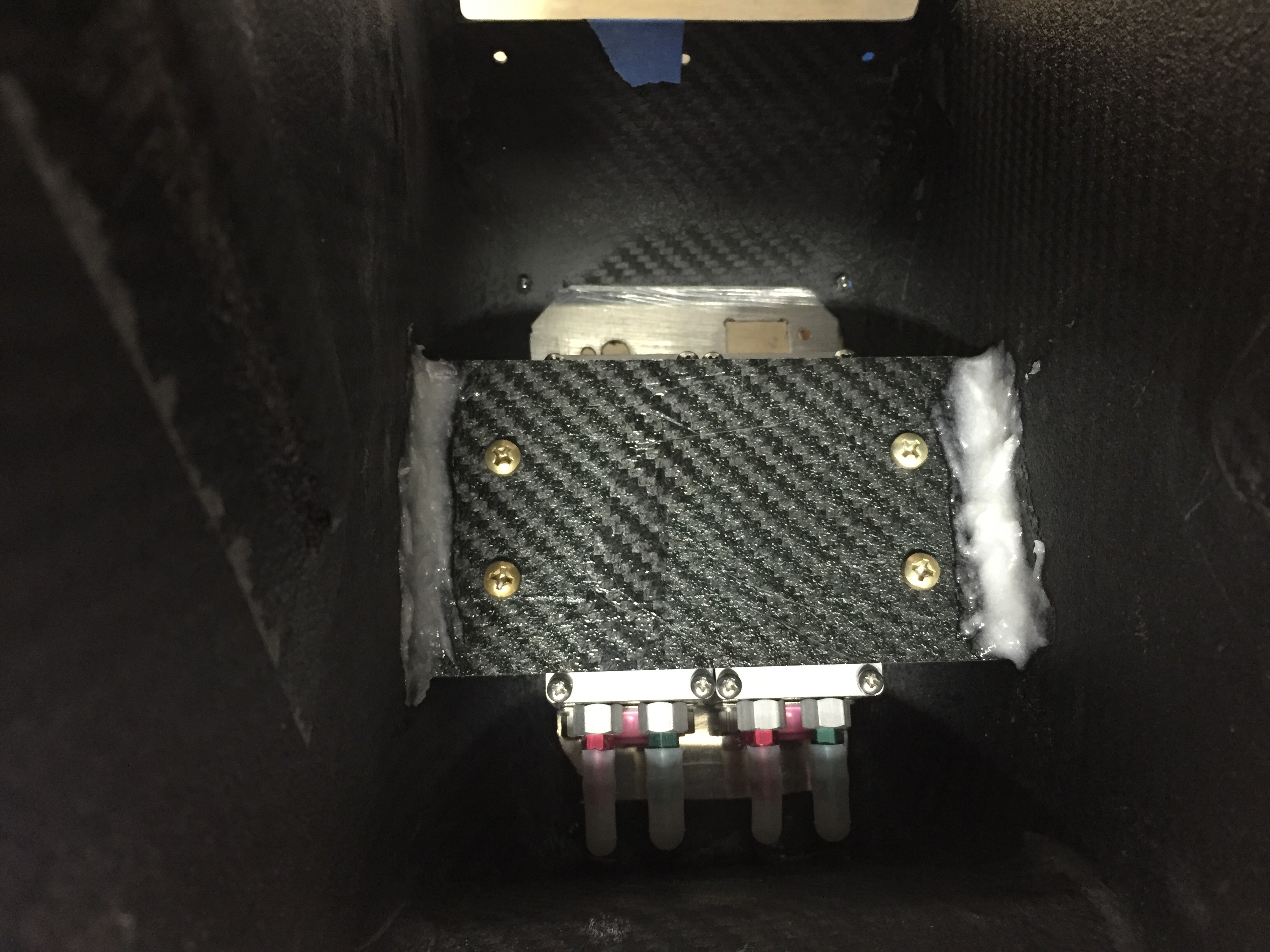
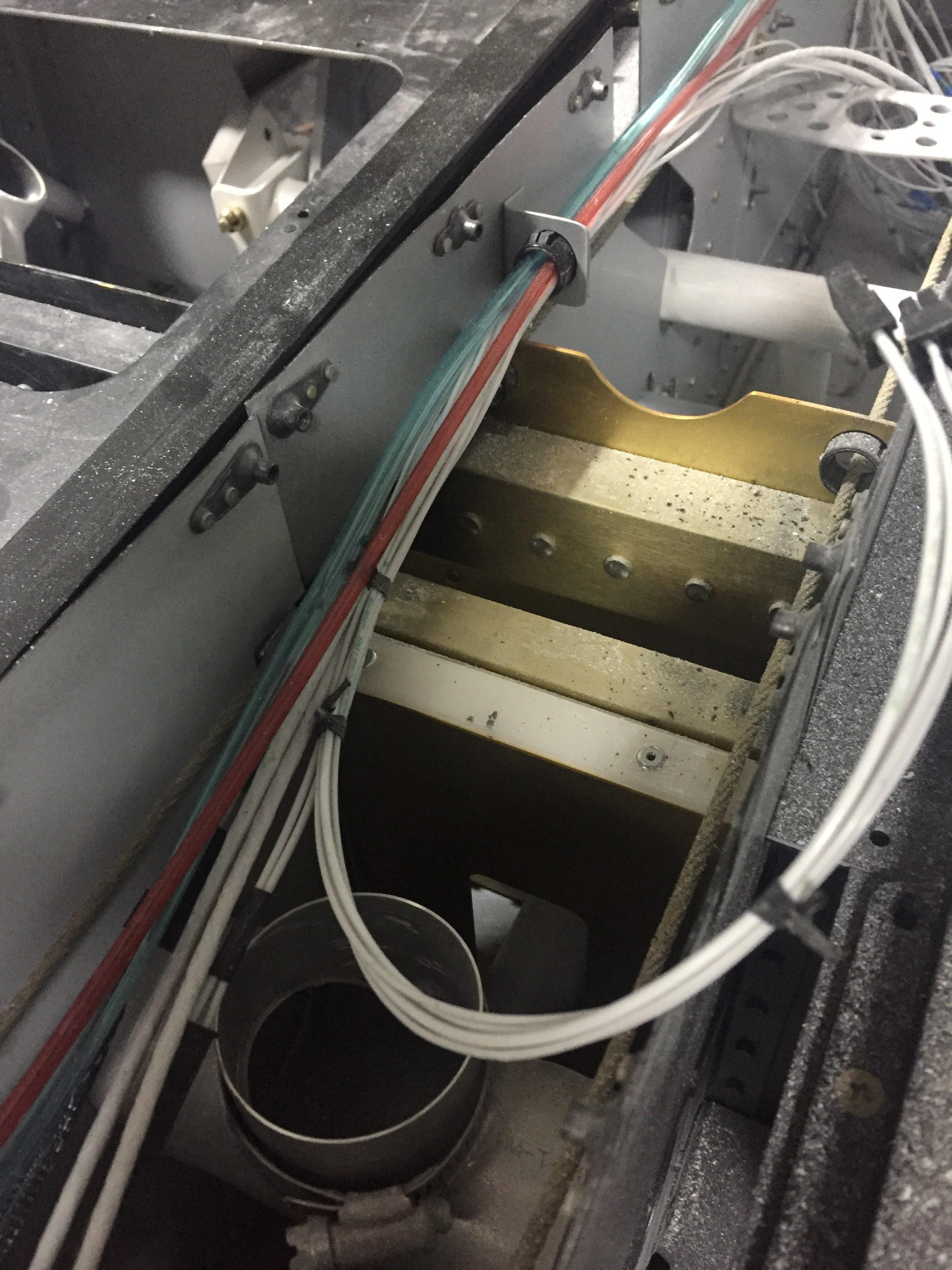
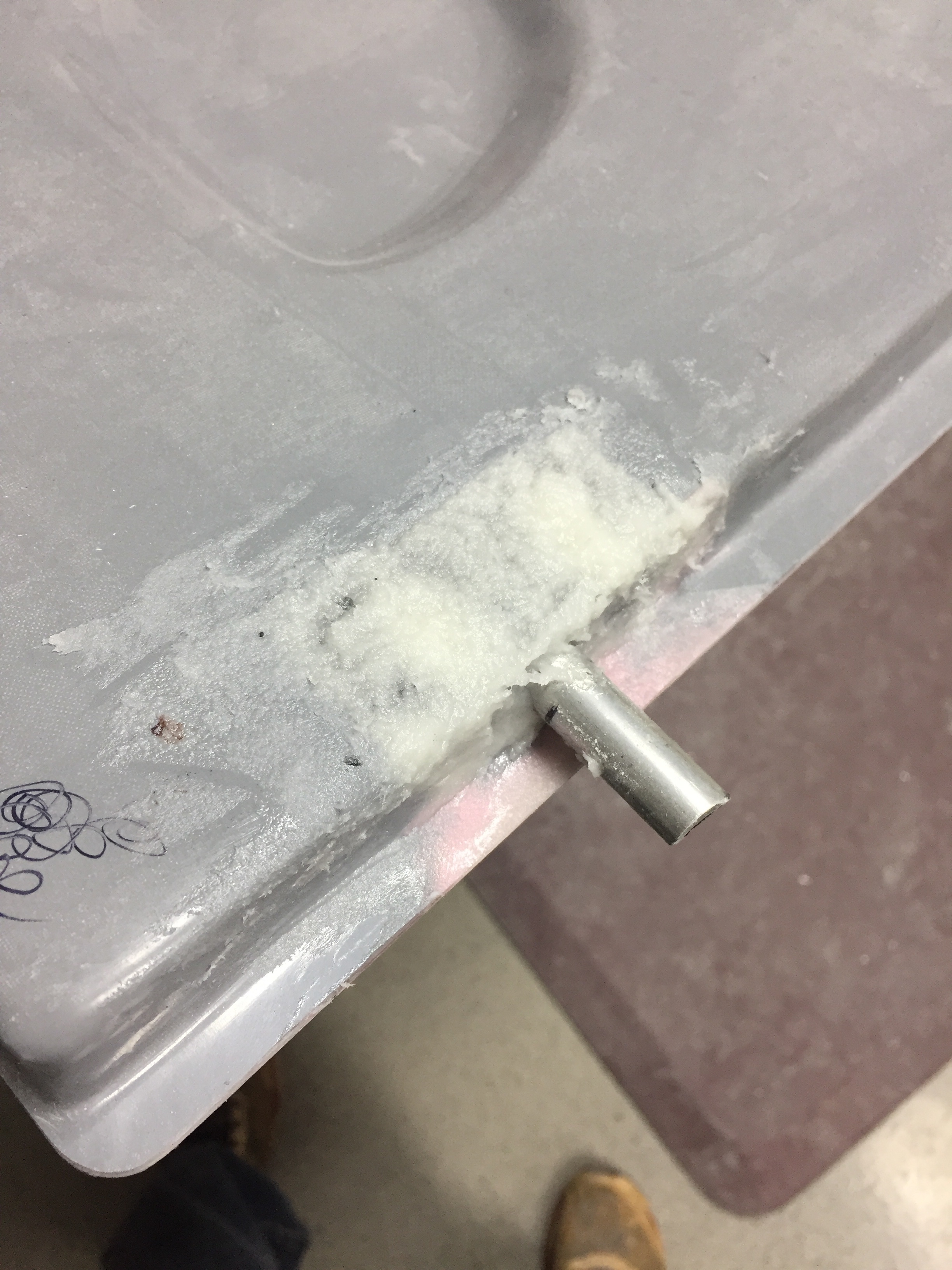
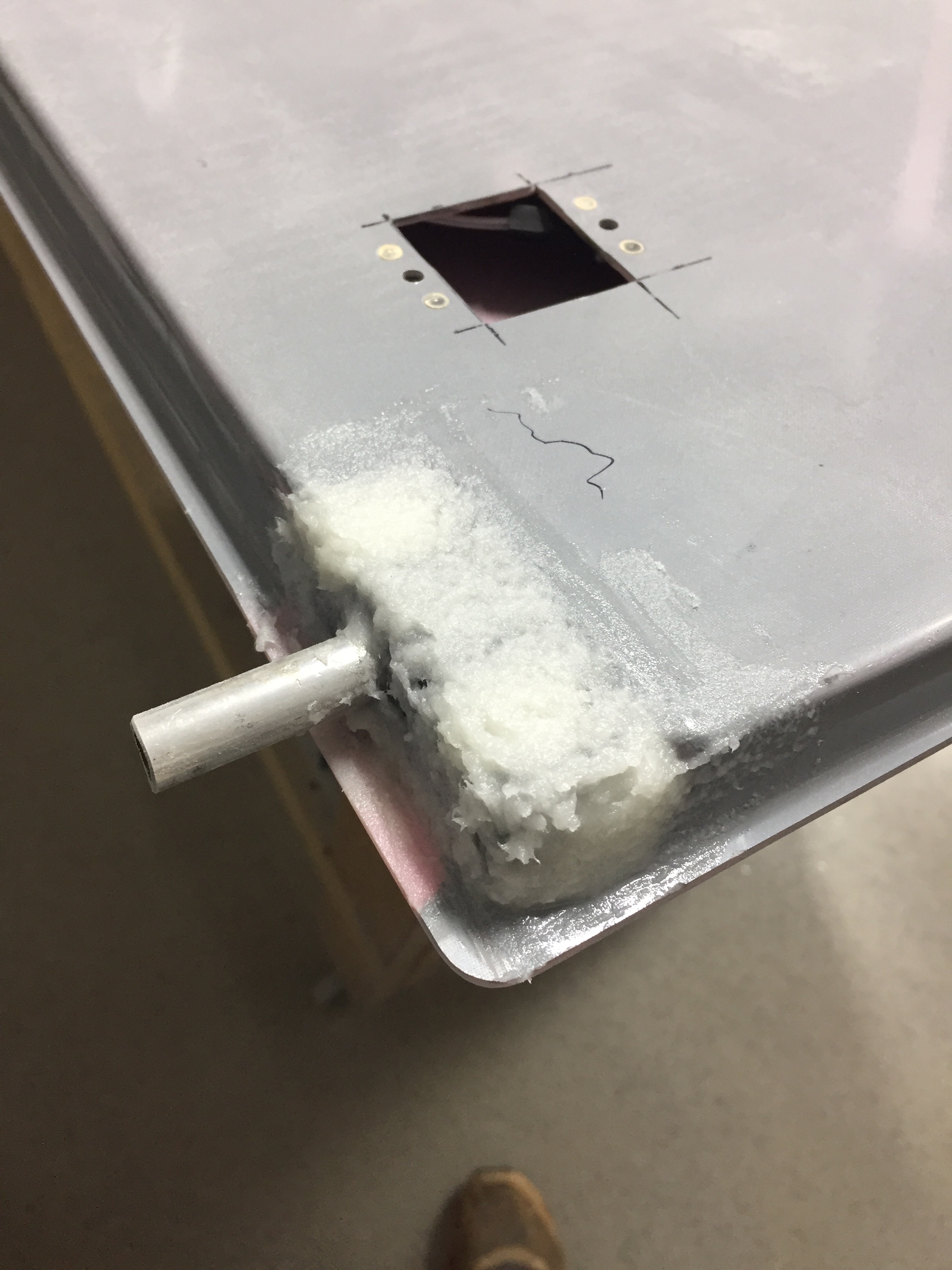
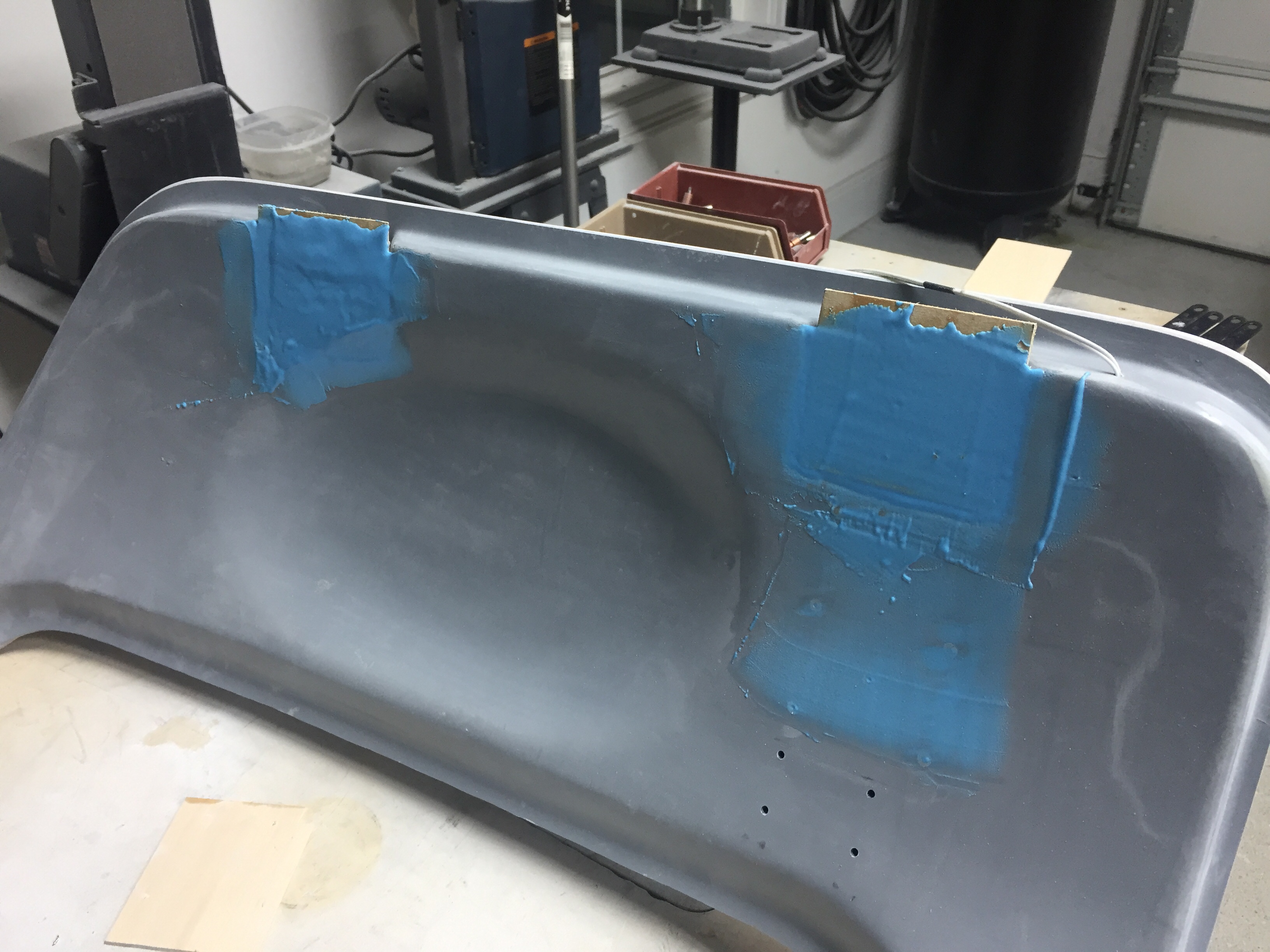
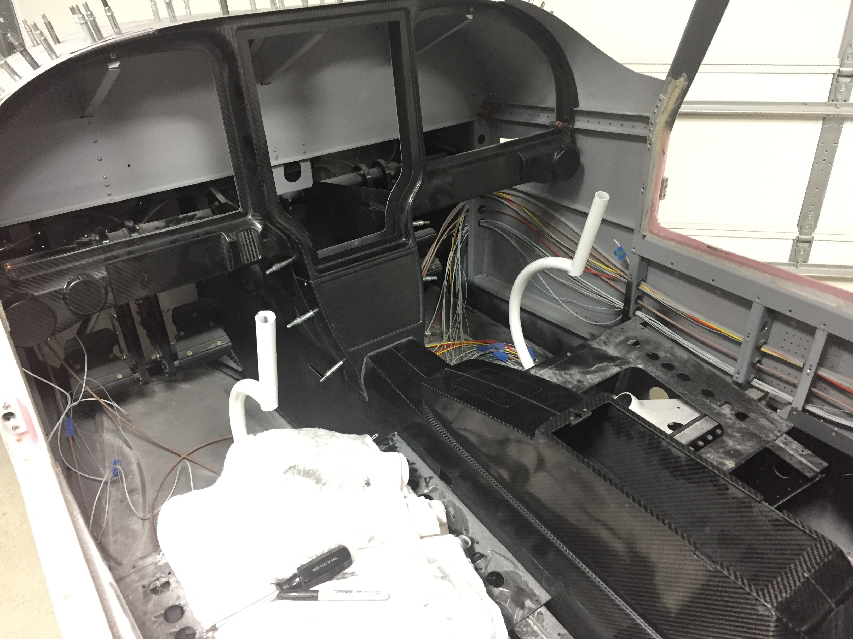
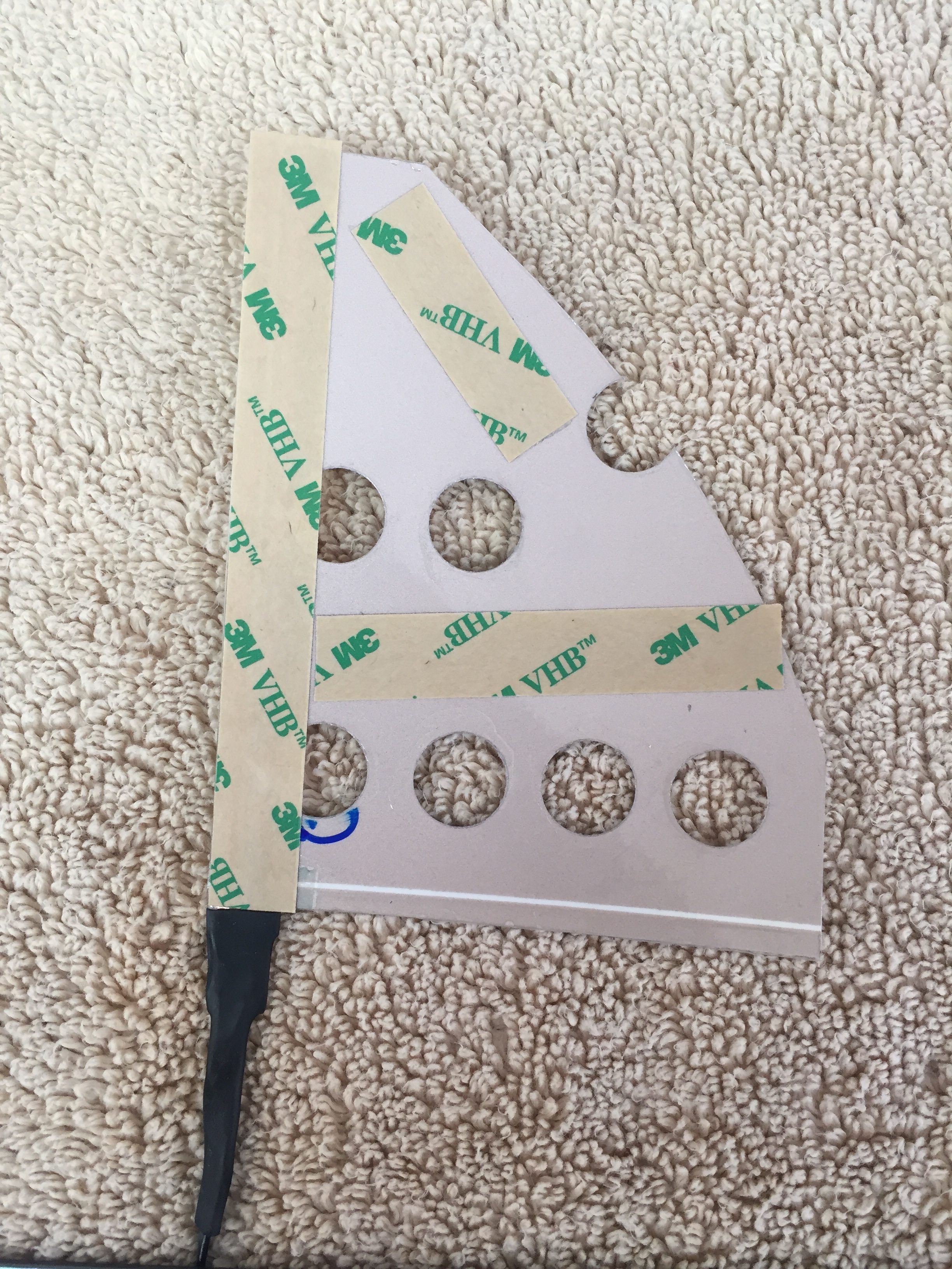
Next task is to cut a relieve for the power leads to rest in.  Since the wire is soldered onto the EL panel, it needs to slip either to the edge or behind the metal panel so that it is all flat once completed.  The areas where EL panels are not near and edge, I cut a slot for the leads to fit through ensuring no exposed lead touches the aluminum.  Several locations will require the leads coming out from the side of the acrylic panel and going into the carbon fiber structure through a slot.  Those are a bit tough to cut out but with patience and a lot of though prior to cutting, it works just fine.  The main switch panel and flap switch panel were the toughest ones.

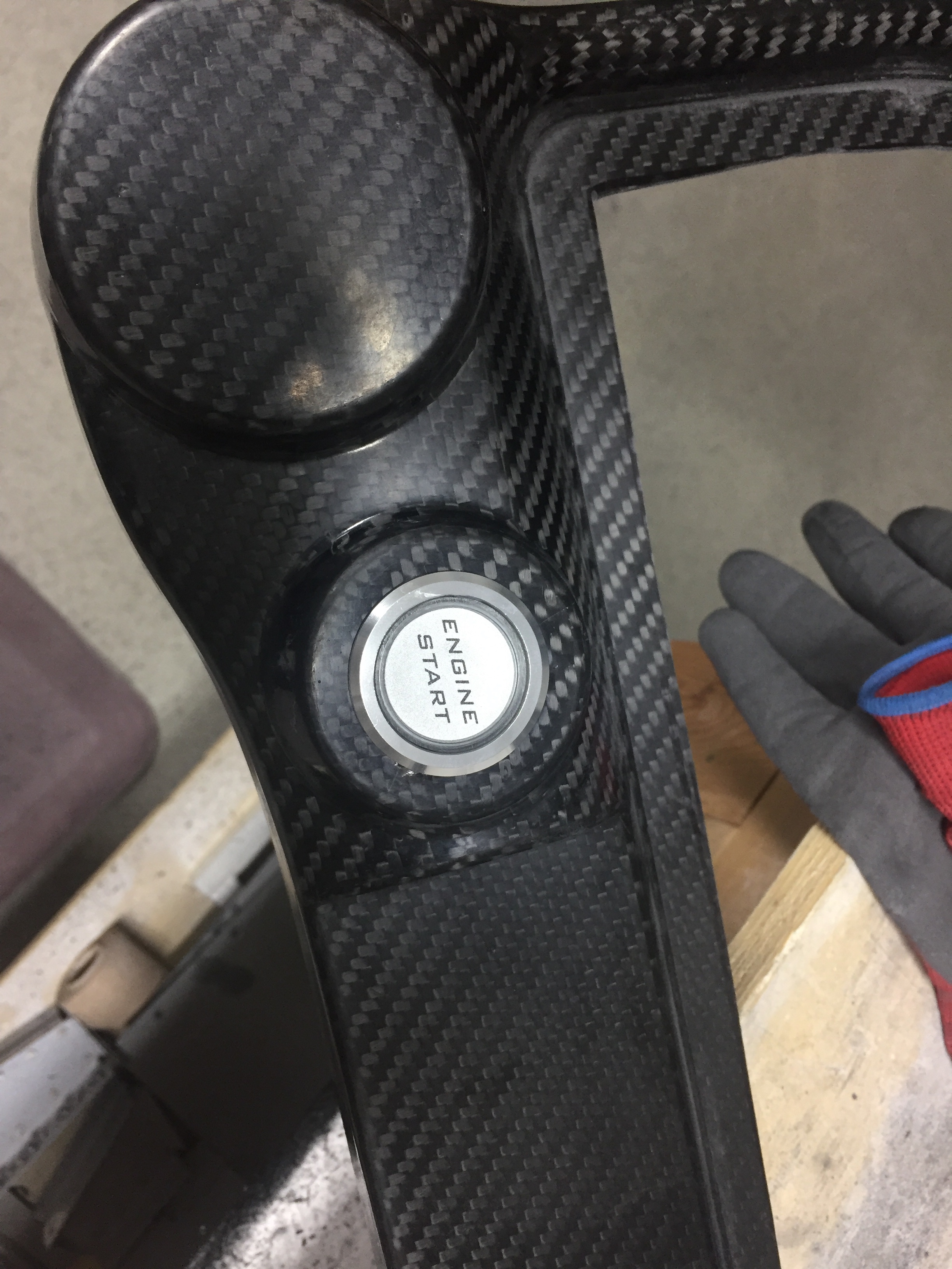
To install it permanently, I cleaned the metal backing panel and positioned the EL panel with 3M clear double sided tape (the same stuff Van’s recommends for trailing edges).  This is really just to hold it while placing the acrylic overlay on top.  The backing is removed from a small section of the acrylic overlay so that I have some adjustment playing the overlay on the metal panel.  Once everything is lined up just right, I removed the rest of the backing and pressed the acrlyic down evenly.

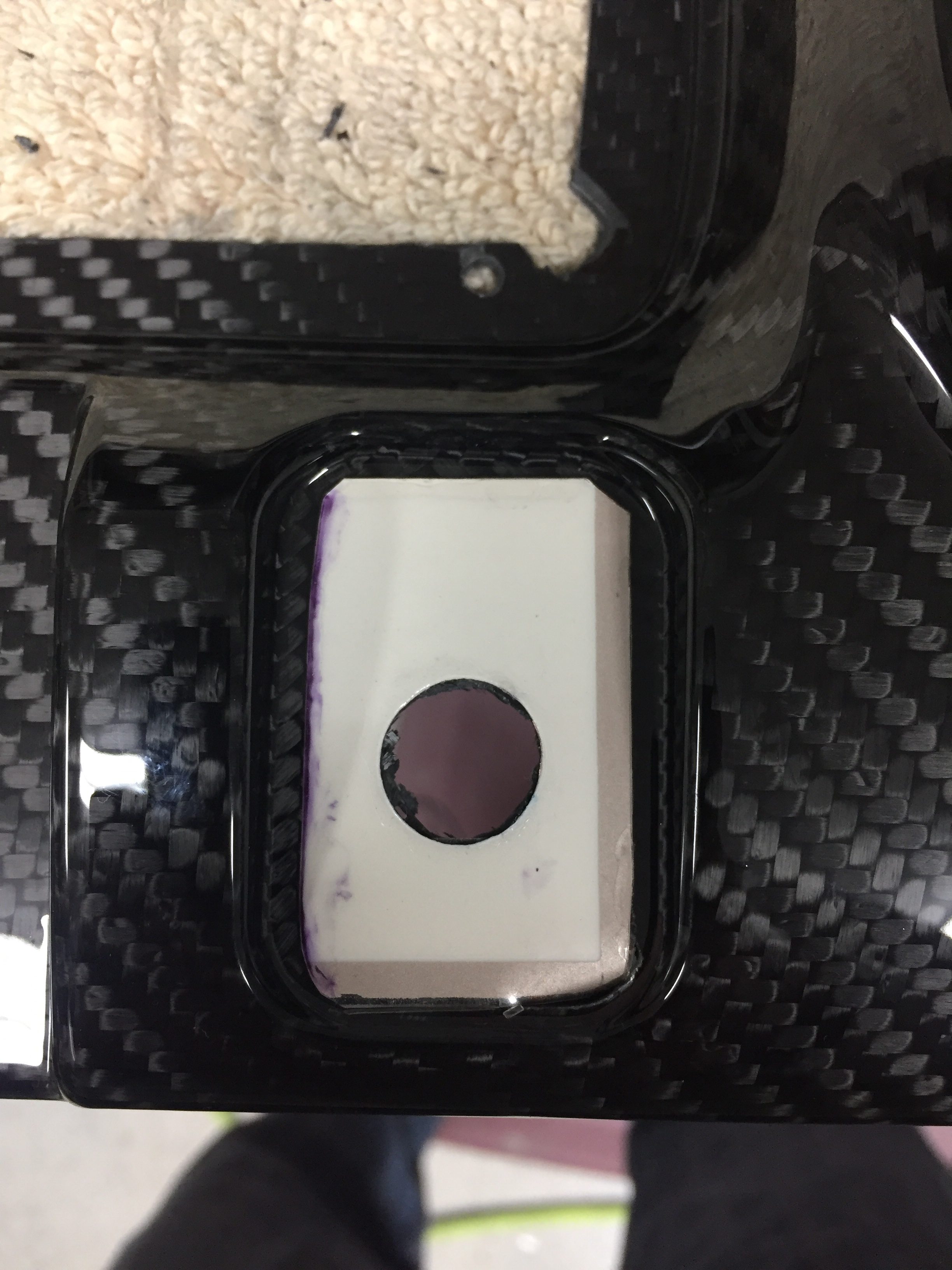
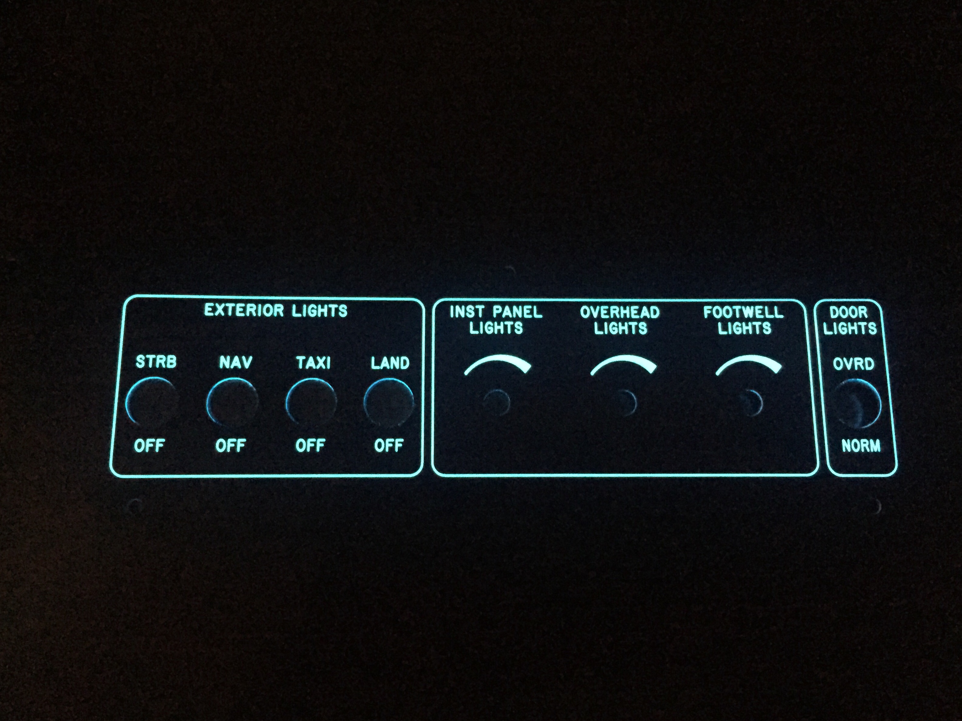
The end result is a sandwich with the acrylic on top, EL panel, then metal panel at the back.  There is just a slight thickness difference over the EL panel, but not enough to be noticeable without really inspecting up close.  If you’re doing that, keep your judgments to yourself!  Switches and dimmers are installed just like you would anything else and before you know it, I was able to screw the panel on the overhead console and fire it up.  I went ahead and wired all of the switches and had the dimmer pots ready to go, so the overhead console and panel is now complete pending black screws coming from AFS!

Overall, I am really impressed with the result and happy I did the project.  It wasn’t cheap, costing about $1000 with most of that coming from the engraved acrylic overlays.  The EL panels were about $200 after all said and done.  The acrylic would have been much cheaper if I had only done the areas around each switch or back light panel, but I wanted a uniform look across the cockpit.  I would absolutely recommend it to anyone wanting a little extra light and wow factor on their build.  The CAD work was fairly simple and fun as was putting it all together.  I can’t wait to get the rest of the avionics and get the whole thing fired up.  She is going to look stunning in the dark!

Bringing up the rear

Now that the carbon fiber bits are cleared, I went to work on the rear panel for the back seaters.  My original plan was to mount the oxygen ports, a USB power port, heat control rheostat, and headset jacks into the rear console but it all just wouldn’t fit.  The O2 ports had to stay there, as I didn’t want them in the side panels due to lack of room, so the headset jacks got the boot.  I drew up a layout based on the measurements of the rear panel area.  The carbon is too thick and rigid for the ports to cleanly snap into so I will use AL with a matching acrylic overlay just like the instrument panel up front.  I was able to keep the power port and heat control on top.  I won’t be back lighting these as there isn’t much room and I figure at night a task light can be turned on easily.

I did need to come up with a way to secure the O2 ports, so I used a scrap piece of carbon and installed a few nutplates before epoxying it into the console.  I had to trim the brackets of the O2 ports so they fit side by side as well.  In the end, it’s a nice fit and still allows easy removal for maintenance.

I used some advice from TCW Tech folks to add a source selection switch into the controller for the rear heat servo.  I had to cut the rheostat off of the circuit board and ordered two matching ones from DigiKey, wiring them up with the control wire going to the switch.  This will allow me to control the rear heat using the rheostat mounted up front or give control to the rear seaters.  Testing with the multi-meter confirmed the desired function so those were tucked away for future install.

Now that I knew where the rear O2 ports would exactly be, I could continue the plumbing of O2 lines.  That also led to running the wires to the O2 ports, power port, and rear heat rheostat.  I fabbed up a few bushing holders to attach to the tunnel and ran everything down the left side.  The front seat headset jack holes were drilled inside the armrest cubby and the wires will be secured onto the tunnel cover.  I placed connectors on all of the wires so that the tunnel cover and center console could be removed for maintenance without needing to remain attached via wires.

I also ordered a four channel dimmer from Pilot Lights to replace the three single channel dimmers for the overhead panel.  They all would fit up there, as space is tight, so this was  a good solution.  I’ll have a spare channel if I want to add anything later.  I chose to epoxy the mounts to the overhead cabin top which kept some of the wiring runs short.  All wiring for the overhead will be coming up through the center post from the sub panel.  I went ahead and fabbed up the wires for the switches and controls on the overhead so I could ensure it would all fit within the post – no issues there.  With that bit done, I was able to close up the overhead console minus the switch panel which is waiting on the back light panel.

Oh yeah, I sanded more on the doors.  You know, the same thing I’ve been doing for months now.  Gah, the damn things are never going to be done.

The art of design

If you aren’t building, you probably don’t care about this article regarding how and why I laid out my instrument panel the way I did.  For those of you that are building, be my guest and read on.

I have spent many Air Ventures looking and playing with avionics and decided some time ago that AFS was my favorite.  I don’t have anything against others, but the layout, functionality, and features of the AFS just fit perfectly for me and my flying mission.  I’m going to fly a lot of IFR with my airplane, as I already do with the Diamond so want a very capable suite of avionics up front.  I also don’t want to upgrade or add on for a very long time so I budgeted to do everything I wanted upfront.

A quick run down of the panel includes:

Two 10″ PFD touch screens

One 12″ MFD touch screen

Dual ADAHRS

IFD 540

Garmin G5 as backup instrument

XM radio and WX

ADSB in and out

Oxygen control head for MH 4iP

A/C control head

Space for SDS control head

Toggle switches and rheostats all matching

All controls that I need located to the left of the center console – no reaching over my pax!  Now, my wife is not a pilot and doesn’t really need the PFD in front of her, but we both like her to be situationally aware and I fly with other buddies that will appreciate a PFD on their side.  It also allows me to one day teach someone else to fly easier.  Again, I don’t want to have to put the airplane down for an upgrade later.  Do it right the first time.

The big pieces go in rather quickly as there aren’t many options of where to put them.  My main concerns were what switches go where and how to get a good flow on the order of switch groupings.  I also was determined to create a back light setup for the switches much like Ed Krantz did on his plane.  More on this later.

With the main components located, I decided on all lighting switches and dimmers to be located on the overhead console.  The upper left has the “misfit” switches like defrost, pitot heat, oil cooler, etc.  The main switch panel in front of me will have master switches and all engine controls in order of startup procedures.  Finally, the lower console will have the O2 and cabin climate controls where either left or right seat occupant can easily control them.

The space for the SDS control head is not ideal, but that instrument, should I go with SDS, is really only used during testing and tuning.  The EFIS will display all engine parameters for normal operations and I haven’t even decided if I’ll mount the display on the panel or remote mount it for use only when I need it.

I do a lot of night flying and despise red dome lights or using a flashlight.  While all three screens and the GPS will put out a good amount of ambient glow, I wanted the switches to be properly backlit to add that extra pop to the panel.  While playing around on the internet looking for lighting solutions, I came across electroluminecsent or EL panels.  They are a really neat product, only about 1/32″ thick and available in many different sizes which are then trimmable with a few restrictions.  All run off of a 12V transformer and provide equal, dimmable, light across the entire surface.  Perfect for what I was wanting!

I ordered a test piece to experiment with in the shop and requested a sample of engraved acrylic from Aircraft Engravers.  Match made in heaven.  The EL panel glows nicely through the laser engraved markings and can be cut, trimmed, and hole punched for all of the switches and dimmers that need to go into the panels.  The transformer makes a bit of high pitch whine, but it will be drowned out in the airplane and a few flight tests in the Diamond confirmed that the transformer was not electronically noisy, only audibly so.

With a successful experiment, I set back to work in Draftsight to come up with templates to be cut and engraved by Aircraft Engravers.  AFS, who is building my panel, will still cut, paint, and label the four main panels.  This will be a presentable back up in case my EL project doesn’t work out in the long run.  I worked with an EL supplier from Etsy who has been awesome to get a proper prototype panel cut for the overhead console.  There are some limitations with the EL panels such as the power lead locations and two edges that have the contacts running along them not being able to be cut.  It was a bit of puzzle work, but in the end fairly simple to draft up and layout.  Aircraft Engravers cut and engraved the acrylic overlay for the overhead console panel and I was able to put it all together with switches to see how it looked.

I was so excited that I forget to specify which color, so Marc sent white.  No worries, as the production version will be a blue.  Needless to say, I spent a lot of time sitting in the dark garage flipping switches that weren’t wired to anything!  It’s a very elegant solution and a rather easy one at that.  For the whole cockpit, all EL panels will be wired together with one transformer and be dimmable through a rheostat.  I wanted all of the instrument panel to match, so I’ll be spending some extra money on acrylic overlays for the entire panel rather than just smaller panels around the switches, but it’s my plane and I’ll do what I want to!  Wayne at Aircraft Engravers has been great and is pretty excited at this working so well, as he may be offering more panels like this in the future.

So now, I have finalized the lighting panels and overlay panels for production.  I’m hoping the avionics arrive on time at the end of February for me to finish wiring and installing.  With my higher level of customization, I’m not using the AFS quick panel switches so I’ll have a bit more work to do than most quick panel customers.  I’m very grateful to Rob, Stephan, and all of AFS for hanging in there with me on this over the top instrument panel.  In the end, I’m confident I’ll have a real show stopper that I’ll be admiring for decades to come.

I love shiny things

While the doors were being worked, I picked up the carbon fiber parts that were at the painters getting clear coat sprayed.  I was smiling ear to ear walking out to the car with them.  The pieces turned out better than I had imagined and are darn near perfect.  The painter put two coats and while it has a nice gloss reflection, it’s not overly shiny.  The carbon really comes to life with the clear over it and I think it’s going to look great in the cabin.  I now regret painting the overhead instead of clearing it.  I have made up my mind if I ever have issues with the paint on the overhead, I’ll strip it and clear the carbon portion without a second thought.

At home, I had to put the push to start button and Aero Vents in to see how it looked and make airplane noises.  Some hours later, I got back to work printed out a few panels to see how things were going to fit and look.  I’ve been working for over a year on my instrument panel layout, playing with this and that, moving things around, and finessing the position of switches, etc.

I started with Panel Planner and really liked it for the ease and simplicity of it.  It is great at putting components in the panel and seeing what it will look like with all the fancy touch screens everywhere.  What it’s not good at is custom anything.  I never could figure out proper switch labels and the 310 switch panels weren’t loaded into the panel template, so I just stuck with the main layout on there.

Meanwhile, I reached out to Rob Hickman at Advance Flight Systems (Dynon) with a few technical questions about the AFS system.  We had a couple great conversations that led to him providing a quote for a “quick panel” customized to my liking.  Surprisingly, he was able to quote a complete panel far less than just the components from Stein!  I had planned on doing all of my own wiring, but I couldn’t pass up this opportunity and deal, saving me money and time.  I started working with Stephan on the layout and wound up using Draftsight Plus at his recommendation to do more detailed drawing on the layout.  I decided to give poor Stephan a break and finish the final details myself as it was just easier and I’m a control hog.  Draftsight is based on a version of Autocad that I used back in high school so I was able to pick it up really quickly.  It’s also much easier and simpler than SolidWorks, as I don’t need computational fluid dynamics to label the Defrost Fans switch and put borders around switches.

The switch panels, upper, and lower console panels turned out great and were a good fit.  I was able to confirm the lack of need to reach across the center console for anything I’ll need in the cockpit except for activating the ELT, a major goal that I wanted after flying the DA-40 and constantly using my right-seater’s knee as a armrest.  Since I had already ordered the Apem toggle switches and Pilot Lights dimmers, I decided to mock up the overhead panel to finish the night off with more flow work and airplane noises.  I admit I’m pretty giddy about getting controls in the cockpit and I’m really happy with how they layout is working.  I can’t wait to get the panel and avionics from AFS installed to light everything up!

Dirty Door Details

I want a really finished looking product for the doors which requires covering / filling in a few key spots such as the pin guides, hinges, and install holes for the gear rack and center cam.  Some have laid fiberglass over these areas, others have left them open, and a few folks are using basswood to create cover plates.  Since I’m better at the wood and had some on the shelf, that’s what I chose to do.  The pin guides I just roughed up and applied flox directly on them, roughing the shape in to match the door lines.  I used some scrap pin material to keep the hole clean.


I used the basswood to fill in a hole used to install the center latch and create covers for the hinges.  It was pretty easy to trim and shape the wood for the plates needed and after I coated all sides with epoxy to harden the wood, I epoxied the plates in place.  I then went back with Superfil and did the final contouring and shaping to match all of the door’s surface.  I’m really happy with how it came out and while it was a bit of extra work, I think it’s worth it in the end to not look at exposed hardware.  I’ll be covering the hinges on the cabin top down the road as well.  Finally, I took some time to fill in little surface blemishes and final shapped the interior edge of the window frame.


After all the sanding was done and I was happy with the doors, I wanted to re-mount them for the final time.  Here is where I realized I screwed up.  The hinges are mounted to the cabin top with the hardware essentially epoxied in (see prior post) so I had to slip the door onto the hinges and install the hardware behind the new cover plate I had spent all that time creating.  Bad idea.  It’s impossible to get the washer and nut on each screw on the door side of the hinge.  My fingers are fat and not triple jointed so I spent an hour raising my blood pressure far beyond healthy limits struggling with it.  I decided to walk away, burn the project to the ground, and start over.  Okay, really, I just took the rest of the night off.  The next evening with a calmer approach, I fabed up a handy little tool to hold the washer and nut in the cavity while I installed the screw.  I used some basswood and some aluminum to create a captive wrench so to speak that worked beautifully.  Had both doors installed in about 20 minutes.  Wish I had put the hinges on the door then bolted them onto the fuselage, but oh well.  I installed the last plates to close out the hinge area and applied filler to smooth is all over.  This completely closes out the hinge cavity on the door not only making it look better but allowing the door seal to work properly.


Meanwhile, I set about working on the instrument panel and center console.  The big Aerosport order had arrived a few weeks prior and I was eager to play with all of the cool stuff.  I started with the instrument panel and got the backing plate and the panel itself fitted in their place.  The side skirts on the tunnel attach to the lower instrument panel with the center console mating up to it.  This stuff is top notch quality and is going to be really awesome filled with fancy avionics!  I took my time to fit it all and used nutplates to ease future maintenance and removal.  I chose to countersink the carbon which left it a little thin and brittle, so I coated each screw hole with light epoxy to help strengthen the area.  I also cut out the main areas which will have the metal inserts leaving a 1” flange to be trimmed to final size later.  The center console was positioned and I used a strap duplicator to drill the holes matching the tunnel.


Since my plans include using the ACM from AFS, I want to use a fancy push to start button but couldn’t really find one that I liked.  The Honda S2000 button others have used are hard to find these days so after a few returned orders, a deep Google search turned up exactly what I was looking for.  It’s a simple Apem NO switch that has a LED light actuator.  It’s also the right size to be proportional to the panel location.  I couldn’t help but to drill the hole and mount it up to see how it looked.


The Andair fuel valve is mounted through the tunnel on the center console as well, so I set about locating the screw holes.  I mocked up the valve itself on the stock mount and will need to create a larger mounting plate for the valve housing down the road.  It allowed me to trim the handle extension and locate the plate on top of the console.  Again, had to mock it up and do some airplane noises while turning the valve.  The noises worked perfectly; so did the valve.


Finally, I cut the throttle quadrant area out and worked on installing the quadrant onto the tunnel cover.  Thanks to Ed and Aerosport’s awesome YouTube video, it was pretty painless and I wound up with a very nice fit with the throttles fitting flush with the console when everything is installed.  I cut a large slit on the throttle friction lock area that allows easy removal of the console.  I’ll create a trim plate to cover up the slit for a finished look.  With the main carbon work done, it was time to drop off the instrument panel parts and center console to a paint shop for a clear coat.  I want to leave the carbon look exposed but wasn’t happy with the finish right out of the mold.  I had originally asked Aerosport to clear the items but they quoted over $1500 just for the clear coat.  I almost choked.  I love them to death and they’ve done a lot to help, but I couldn’t swallow that pill.  A few calls around the area and a local custom motorcycle paint shop could perform the work in four days for $250.  We’ll see how they turn out next.

Fun with electrons

While waiting on the finish kit, I worked on a few electrical to do’s on the build. The AC system is installed, but all the wiring still needed to be hooked up. The system’s controller uses relays and I decided to move the location of the fuse panel to the bulkhead for easy maintenance. The relays were labeled and mounted to angle aluminum on the equipment tray. A lot of wire connectors later, the relays are all hooked up and the wires up front are pulled. I also wired the condenser fan with a disconnect for future servicing. The only wire not run is for the compressor, as I may go with an electric compressor depending on a few things down the road.

I also received a sample of the electroluminescent panel to experiment with backlighting my instrument panel. Aircraft Engravers sent me a sample panel on acrylic that I put on the EL panel and am really excited about the results. The EL panel put off a nice amount of light and dimmed well. The sample panel looked great and is easy to produce as well. My plan is to have Aircraft Engravers produce the panel overlays in acrylic which I will mount on top of the metal panel inserts holding the avionics. The EL panel will be sandwiched in between. In theory, it will be a nice clean look to the panel and have a high end backlight to boot. I took the EL panel with me in the Diamond on a quick flight to see if there was any noise from the transformer and didn’t notice any issues. Not a overly scientific test, but enough to keep me motivated to make this work.

I only had a 1″ strip, so you can see the difference where the panel is not backlit. The EL panel is also white when off, not the typical pinkish so the panel during the day appears to have white lettering as typical. More to come on this!

This could be instrumental

One section that I skipped over is the forward fuselage / instrument panel section.  This needs to be done before the cabin top goes on, but is left off while working on the firewall area and rudder pedals.  I had all the parts down so wanted to get the assembly together and out of the way.  Part of the fabrication steps require the use of the stock panel blank, which I don’t have since I’m using the Aerosport panel down the road.  Fortunately, Parish had the blank and I was able to borrow it to complete the related steps.  I paid him back by fabricating the two curved supports.  The plans call for using fluting pliers, but there is no way that was going to happen.  Fortunately the sheet metal shop on base has some great tools and even better craftsmen that were willing to help out in exchange for a few adult beverages.  All four pieces turned out beautiful and matched up perfectly.  It really is all about having (access to) the right tools!

Once all the parts were prepped and primed, assembly was frustrating as the AN470 rivets are difficult to buck in thin metal.  I just have bad luck / technique when trying to hit these on thin structures.  One or two drilled out and replaced after a few deep breaths and it was ready to go back into storage.  This will most likely be modified once I have the panel and some avionics depending on location and dimensions of the components.