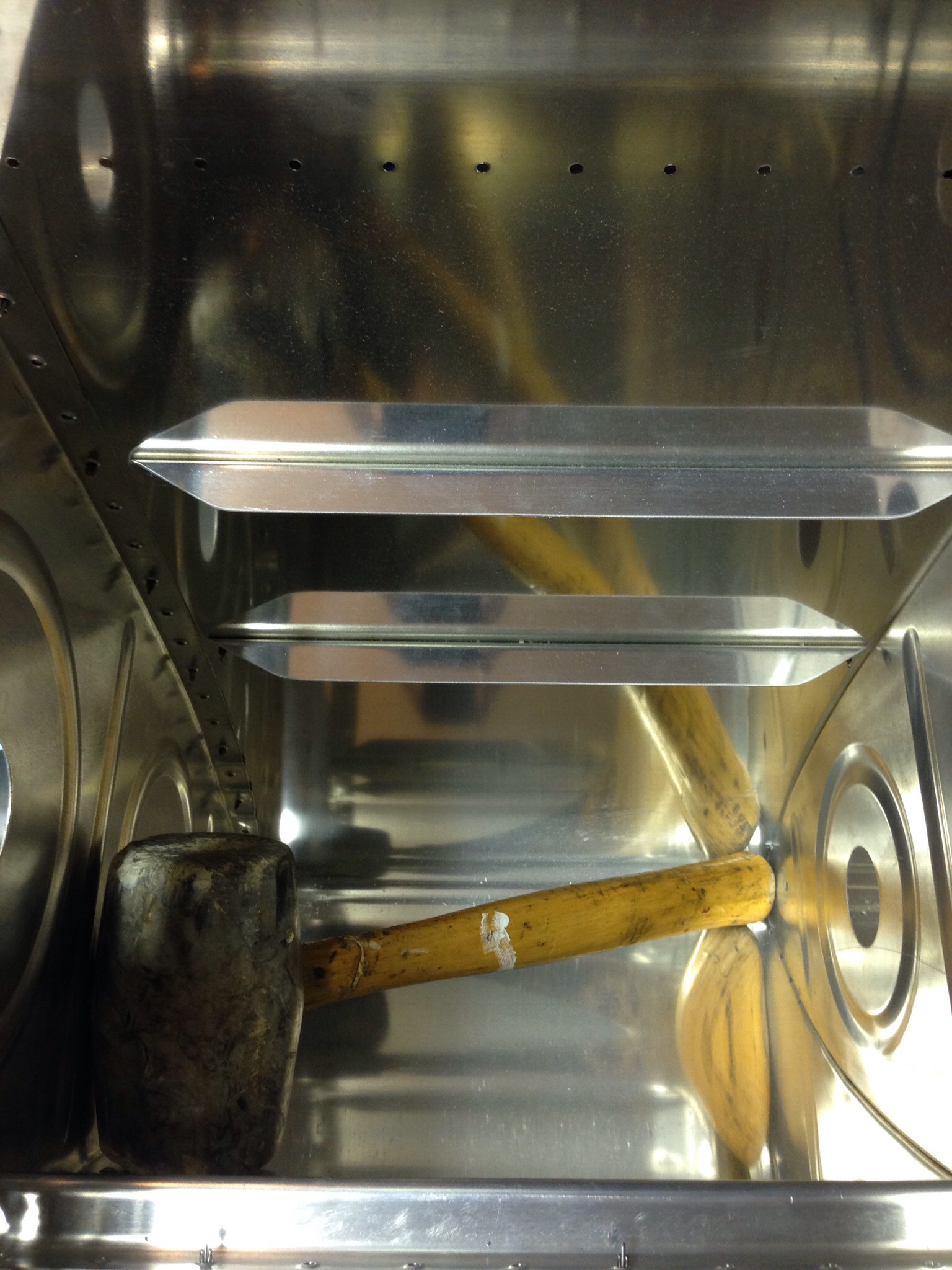
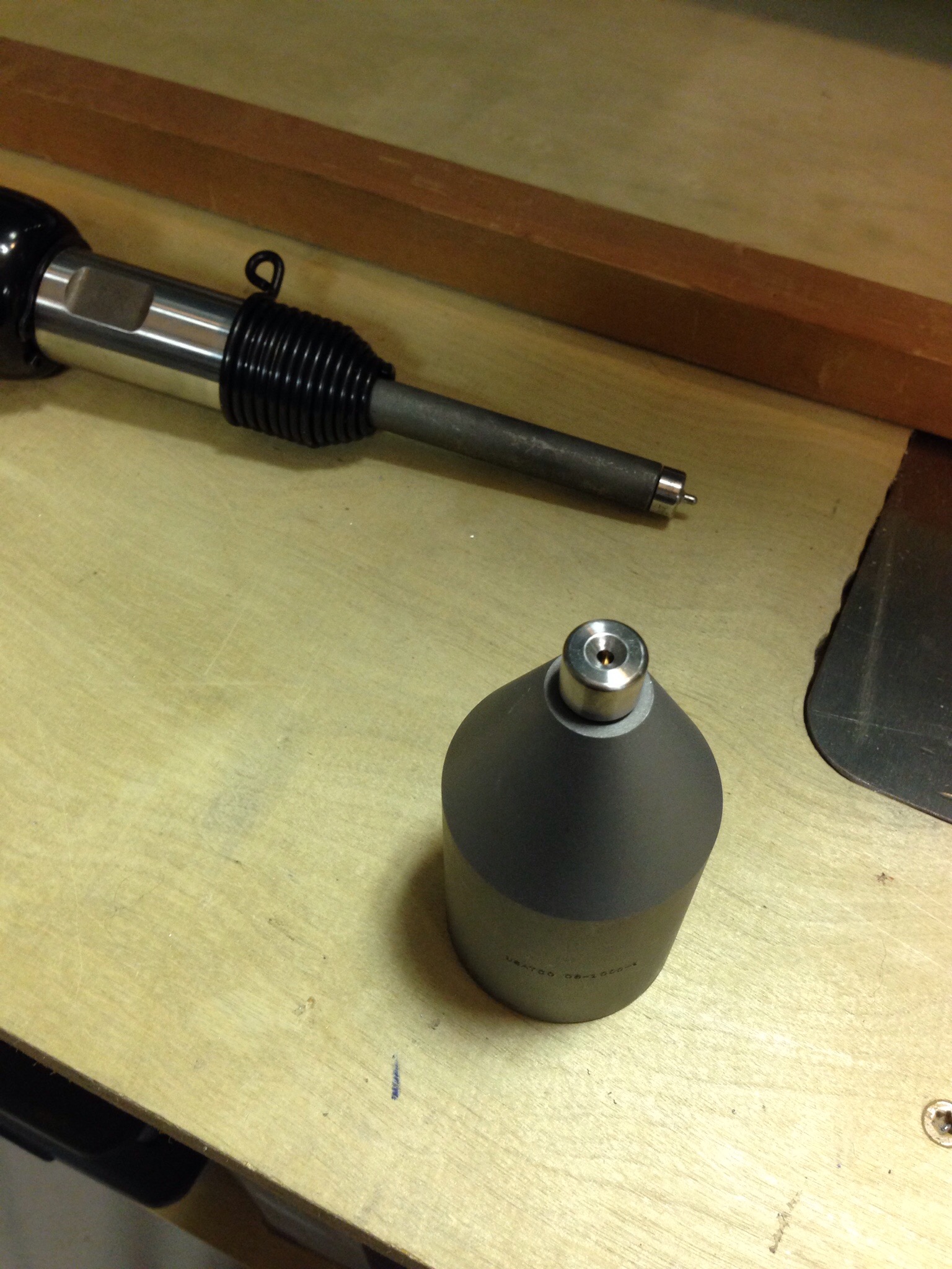
With the drilling and deburring complete, it was time to use yet another new tool that has sat in the toolbox for far too long. This is a bucking bar and rivet set that allows you to insert dimple dies and dimple areas that the c-frame can’t get too. It was useful on the leading edges of the tank skins in the middle of the skin. I did learn, however, that the dies don’t like this tool, especially with a side load on them. I broke two sets of dies. A quick call to Avery and a replacement along with the SafeAir1 pitot mast was on the way.
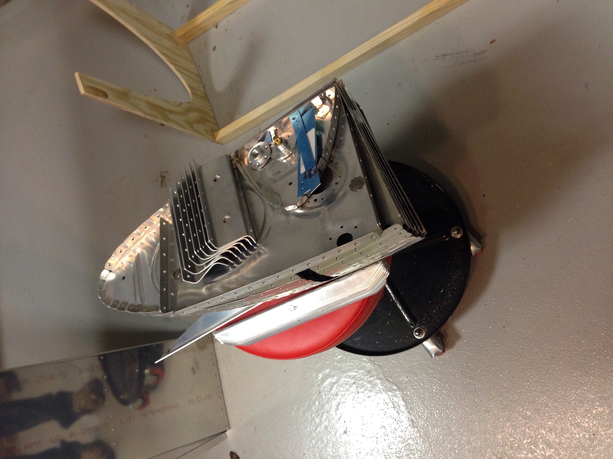
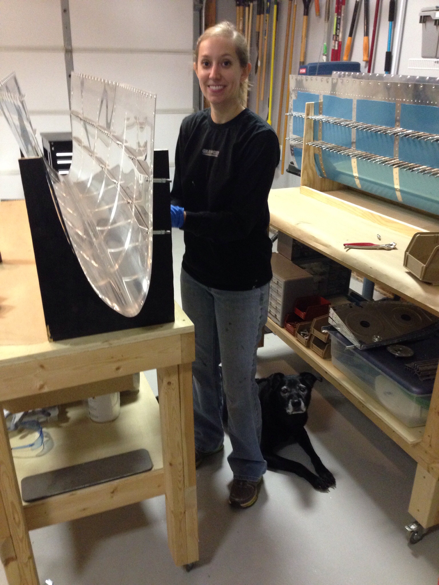
 It’s hard to believe that almost all the components of the fuel tank can fit on my little stool. I scuffed the joint surfaces to promote adhesion for the Pro Seal on all the parts. These are all set for final installation into the skin.
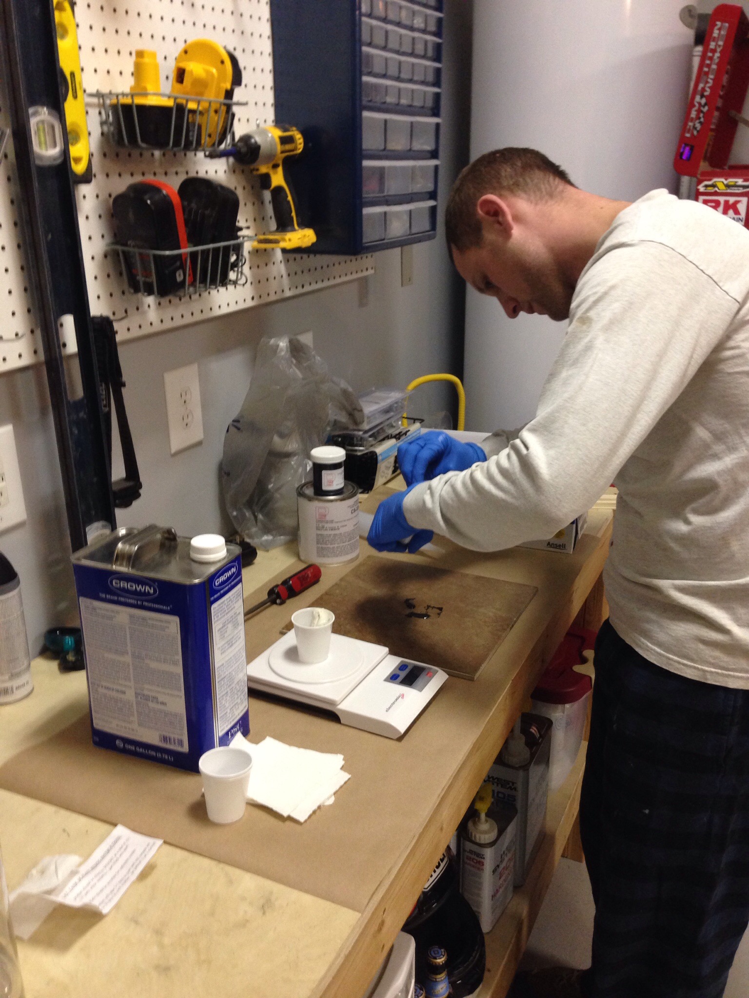
 This is where things can get sticky. The biggest advice I read was to be prepared for working with Pro Seal and to wear two pairs of gloves while replacing the outer pair often. Once Pro Seal touches a surface, it doesn’t come off without MEK. I used a postage scale to weigh the components, ceramic tile to mix, and the applicator gun from Brown Tool. All that equaled a clean, easy process of using Pro Seal.
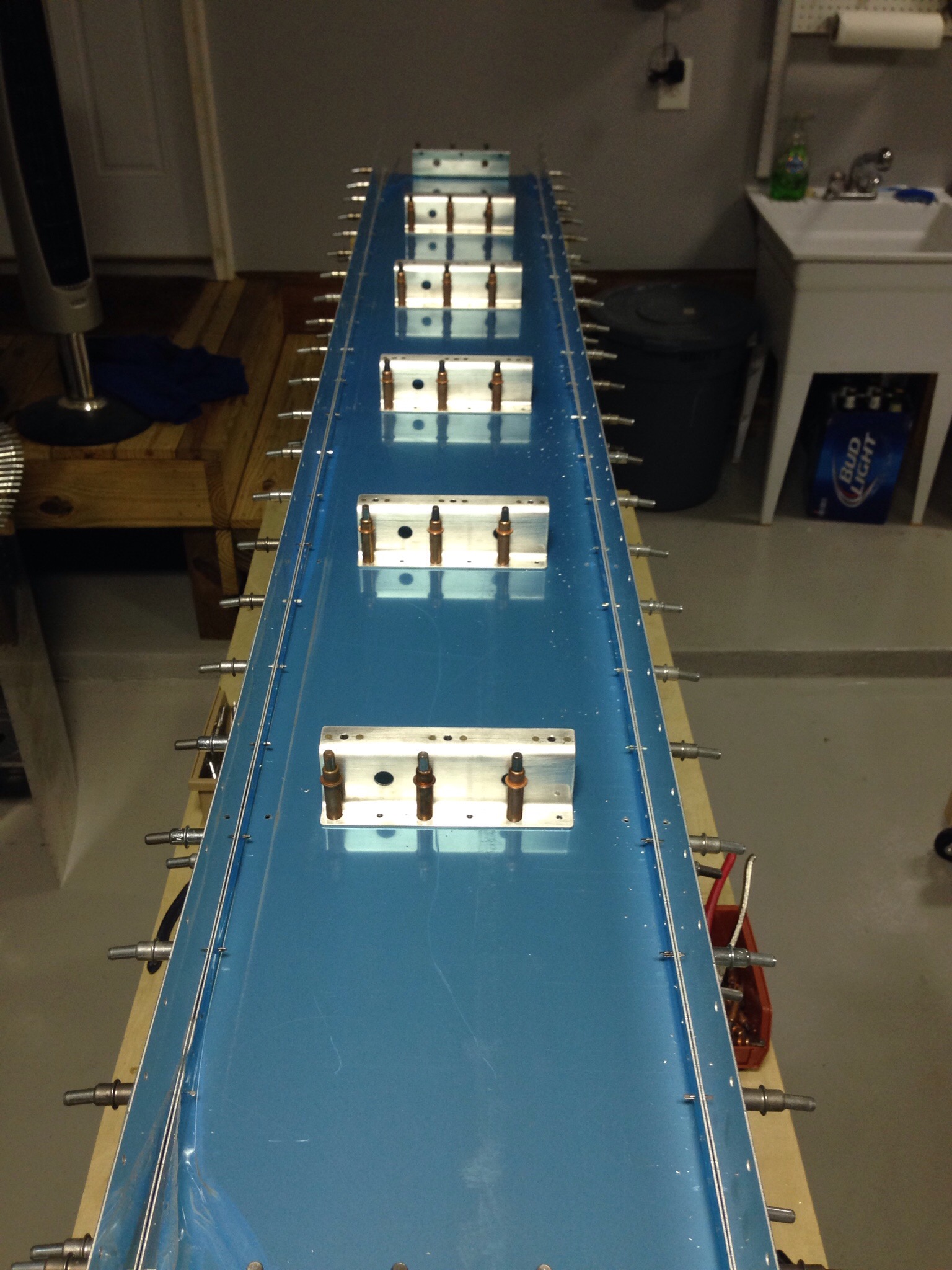
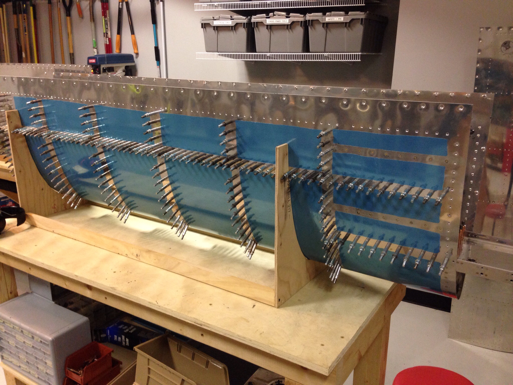
 The wife-copilot-cobuilder-photographer came out to help and we started with the stiffeners. I chose to 100% cleco the parts in place and come back for riveting the next day. It greatly reduces the mess and actually makes riveting easier. Kayla the flight engineer dog came out to support the project as well. The next day, I came out to rivet the stiffeners with a dab of Pro Seal in each dimple to seal the mfr head of the rivets. Turned out well with the tank die dimple, as it’s a nice flush surface.
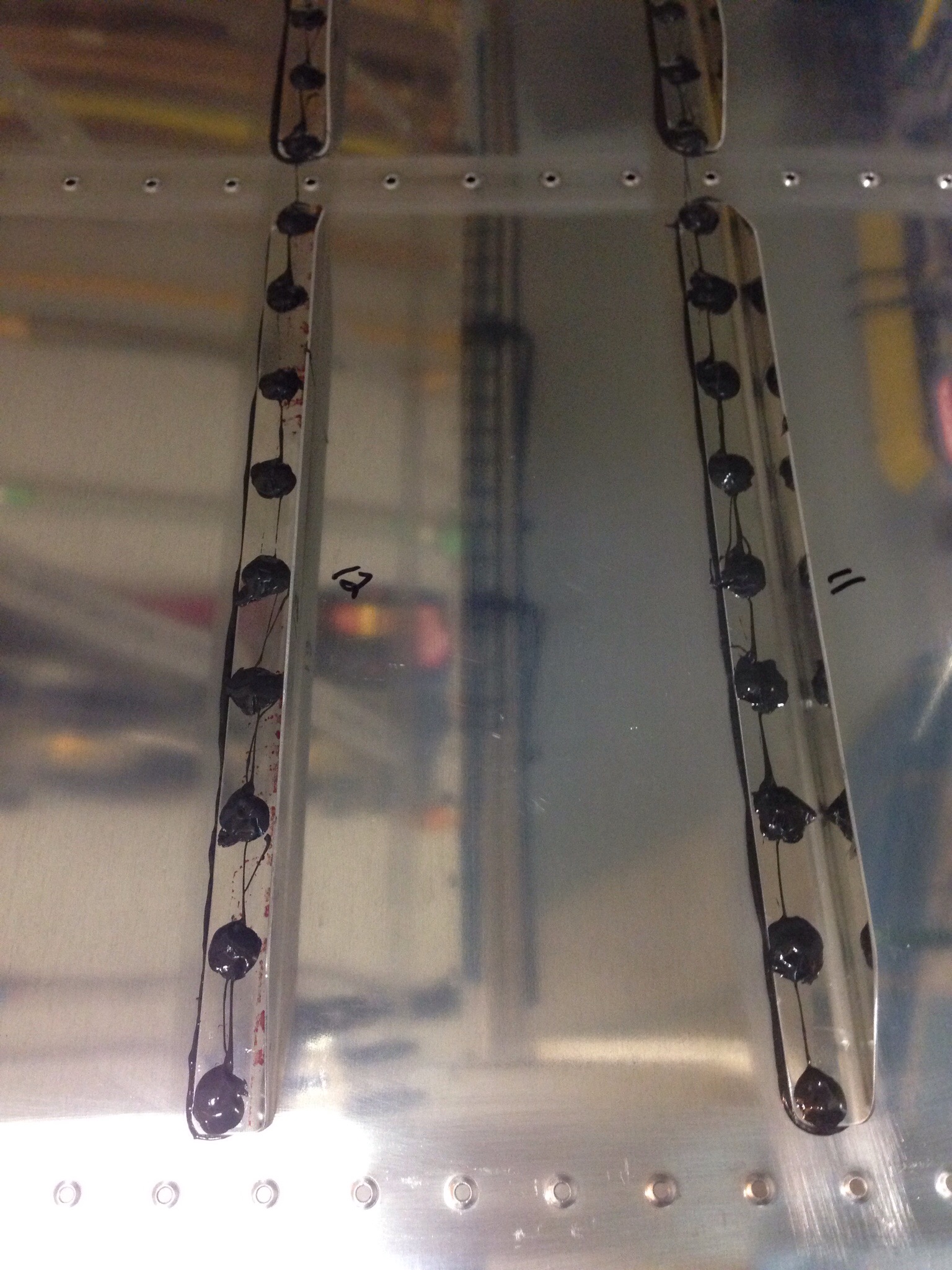 I went solo and finished up the ribs and the j-stiffener for each tank after mixing up yet more sticky stuff. I found that letting the sealant cure for one day was perfect for riveting, so the following day was spent riveting the ribs and j channel. I also went back and put a blob of sealant on each shop head, completely sealing each rivet (hopefully) to prevent any fuel seepage.
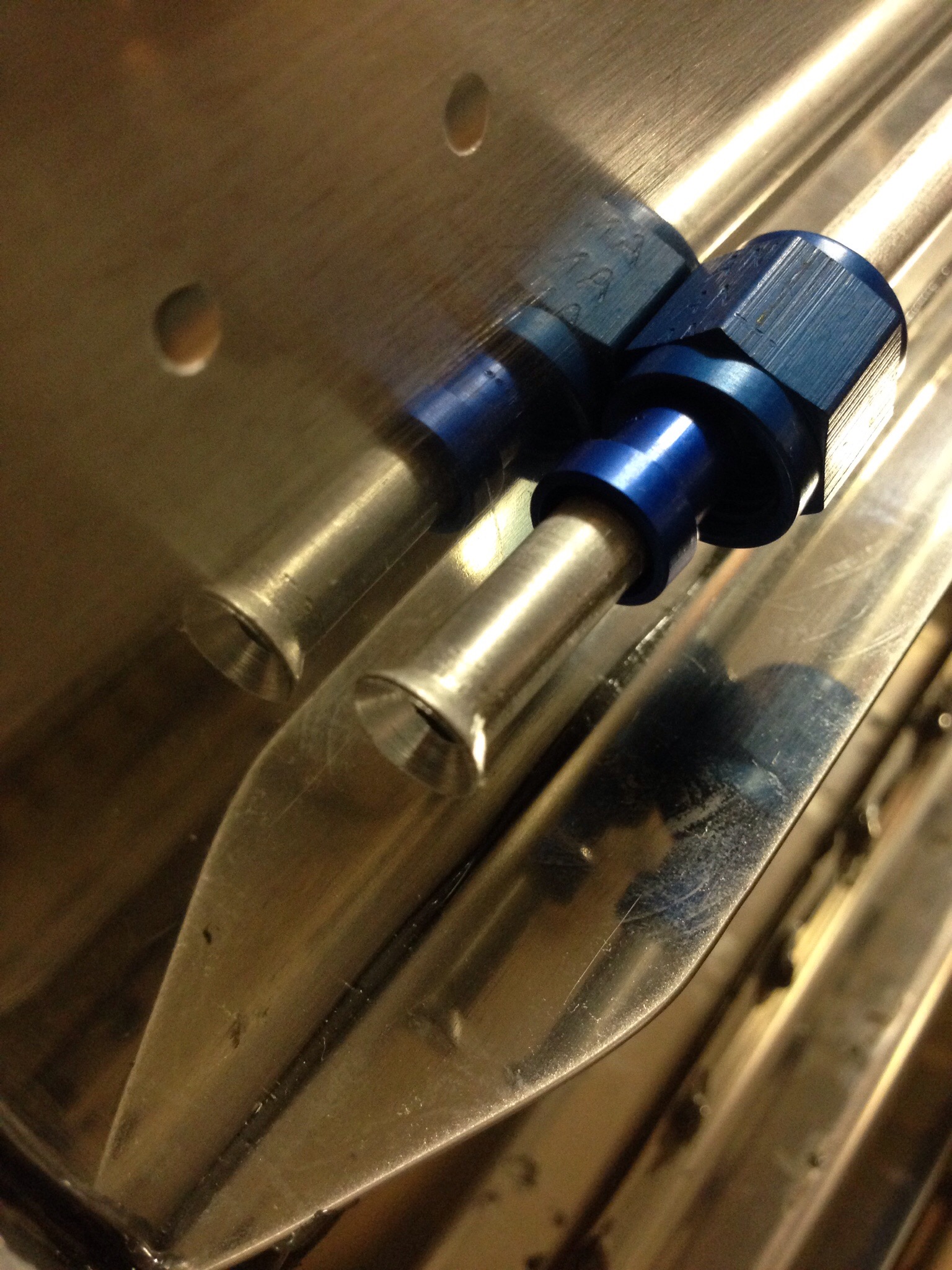
 The next step is to fabricate the fuel vent lines, which consists of straightening very carefully the aluminum tubing and flaring one end to accept the AN fitting through the end rib. I skipped ahead on the plans and riveted the end rib on before putting the line in, but was able to easily work around it. None the less, it’s a good lesson to stick to the plans. Pro Seal is permanent, so no going back and redoing!