Service Bulletins

While having some down time at home that I can’t do much productive anything with, I decided to research quite a few things while lying in bed after surgery.  One of those was service bulletins.  There are a handful out there for the RV-10 and are a lot like AD’s issued by the FAA, but they are not mandatory by law.  Highly recommended, however, so in the home built world, you comply with them.  With this being a build log, I wanted to document them here and then I’ll make the associated entries in the air frame log book once I have one.

The empenage kit (oldest original kit) was delivered in October 2005 to the original builder, thus I have only addressed those SB’s relating to the dates affecting our kits.

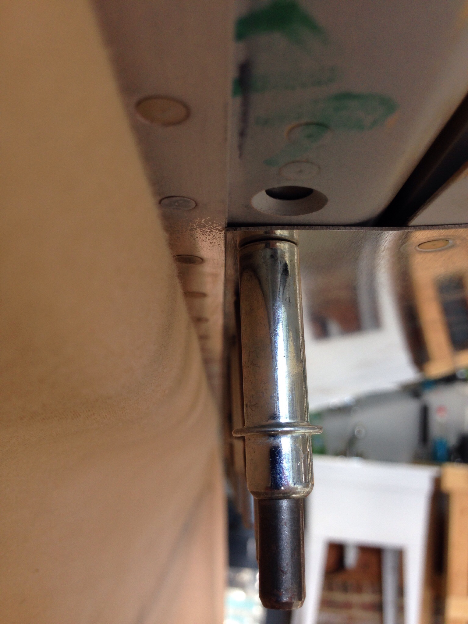
SB 06-2-3 is for the vertical stabilizer rudder mount.  This SB was completed by the original builder and complies with all aspects of the SB.  I could not get a good picture inside a tiny access hole, however, visually confirmed the doubler plate is in place inside the main spar of the VS.

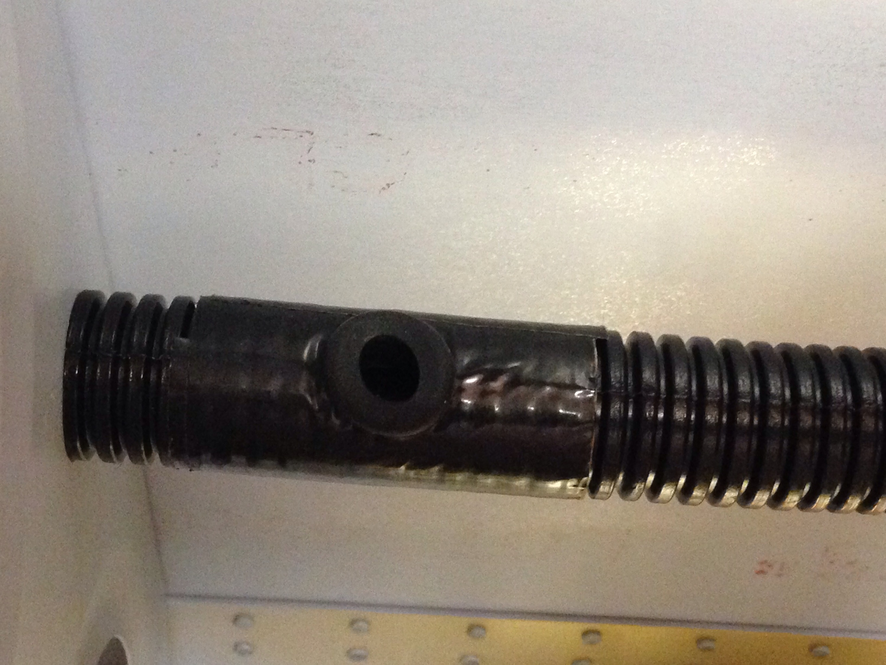
SB 06-9-20 is for the trim cable anchor nut on the elevators.  While our kit does have the double welded nut, I chose to upgrade to the CNC machined piece by IFLYRV10.com.

SB 08-6-1 is for the F-1010 bulkhead near the vertical stabilizer in the tail cone.  My kit came with the SB contents and I completed it as part of the original build of the tail cone.

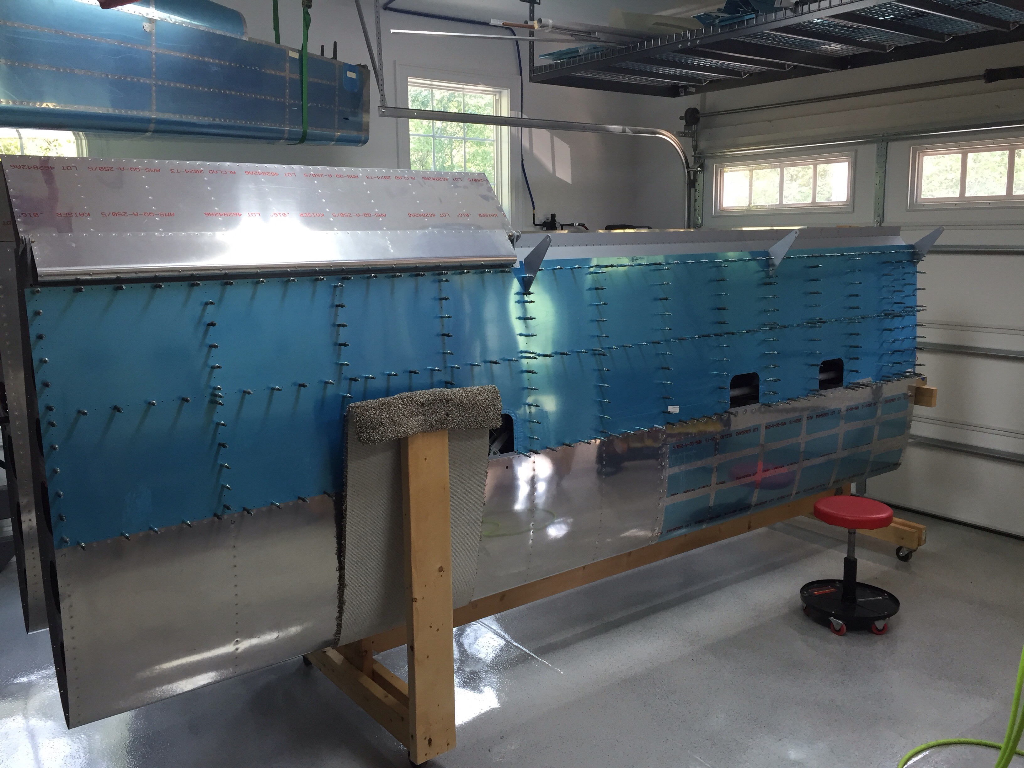
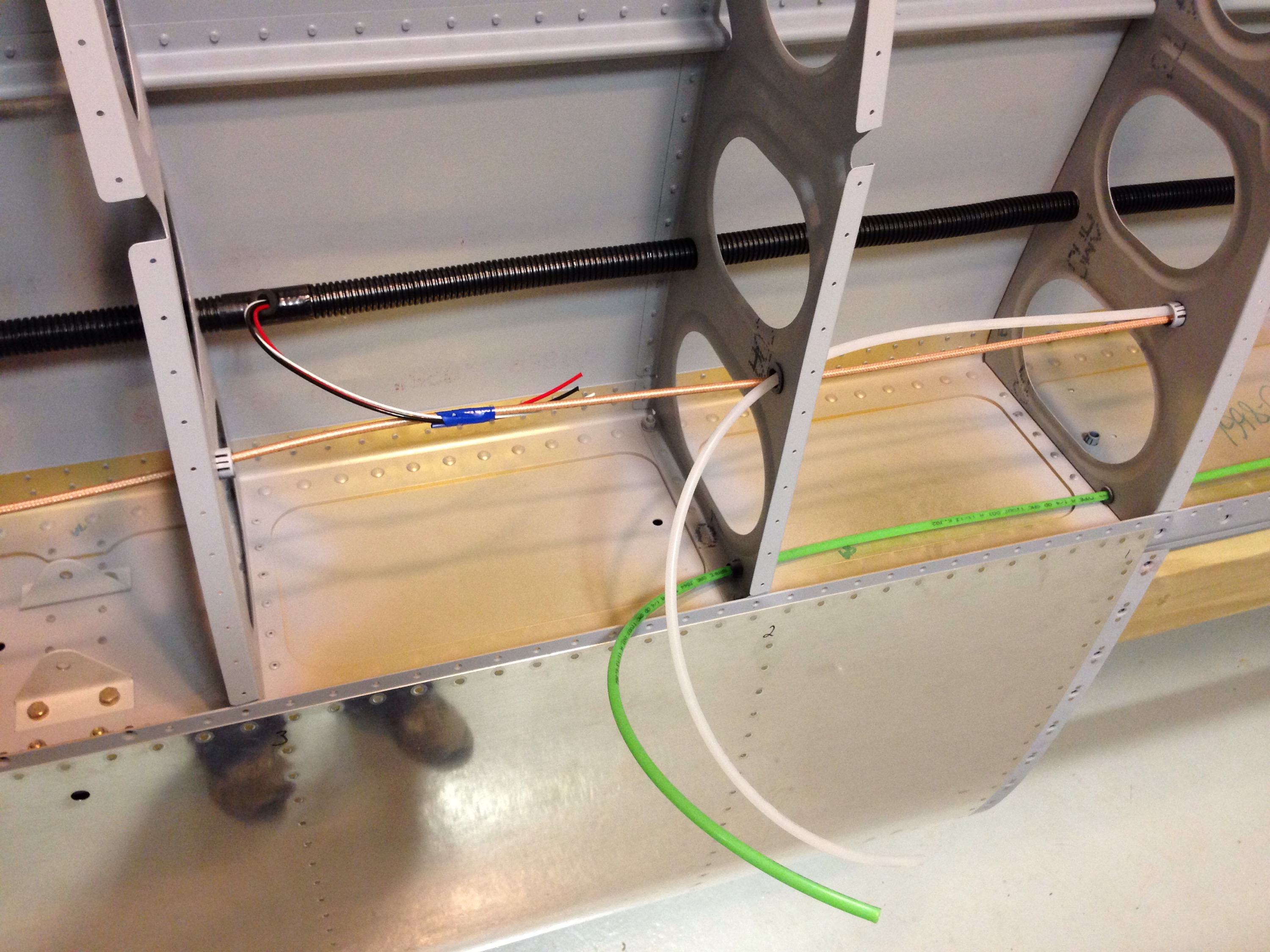
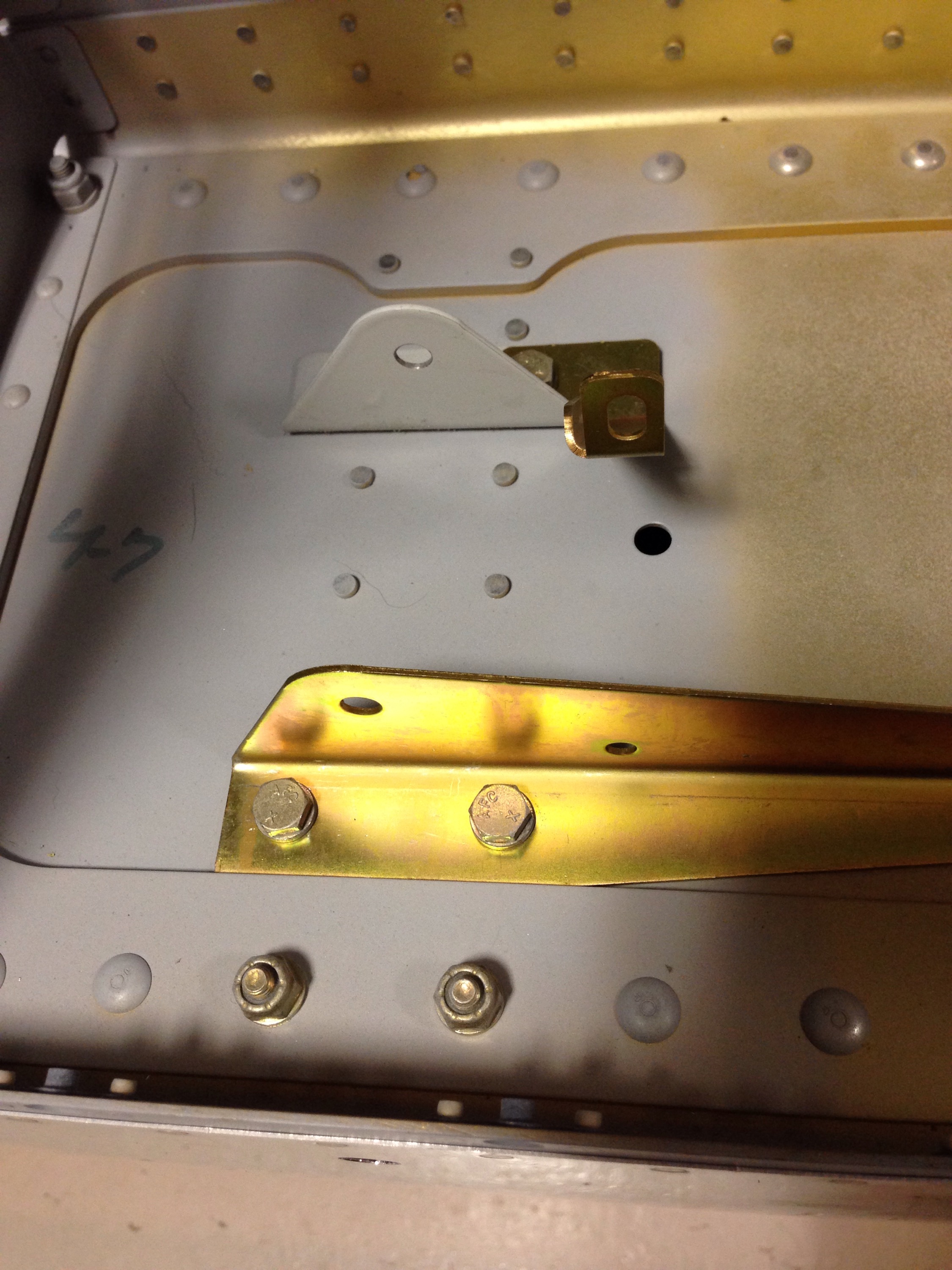
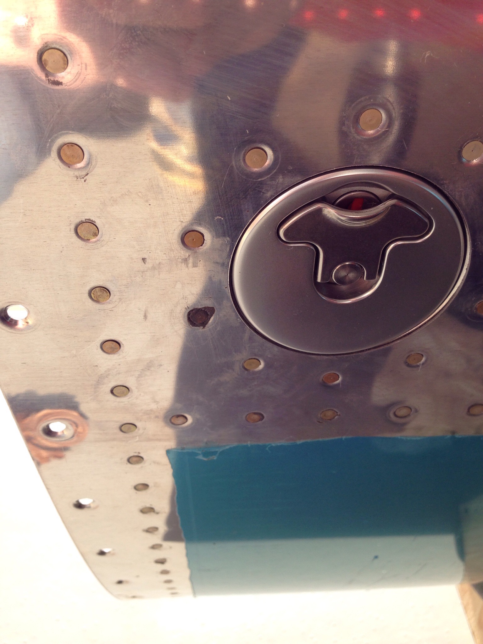
SB 16-03-28 is for the aileron hinge brackets possibly cracking on the inboard aileron mount.  I have removed the portion of the gap fairing to allow future inspection and no further action is needed until flying, at which time an annual inspection of the bracket must be made and noted in the log.

There are other SB’s that will affect our build, however, I have not gotten to that stage of the build yet, so will cover it in another post.

I’ll be right back under construction

After almost a year and a half, construction on our RV-10 is back under way!  Now that the new shop is done and organized (check out the Garage Part Deux), I’m making time to get the build back on the top of the priority list.  With as much time away as I’ve had, I decided it’d be a good idea to review the plans and remember just where I had left off.  The last check mark was in the aileron rigging section, so that’s where I dove in.  I decided to go ahead and rig the control surfaces before riveting the bottom skin on just to have easier access and am glad I did.  If needed, I can always remove the large pushrod now that it’s all tweaked to have the surfaces lined up properly with the control arms.  I also added the spring attachment points for the aileron trim servo, having made the servo mount a while back.

Next up is buttoning up the wing bottoms.  I took a long last look at both before moving forward and read a lot of blogs to see if I could do anything else before losing easy acces.  I’m glad I did because I realized I had the trim servo wiring going to the wrong spar location.  That was a quick fix and I’m now confident I’m ready to put the bottom skins on.  The only item left to add is the pitot tube mount, but the bottom skin has to be attached first.


I did have to modify the rack yet again as the carpet post was too tall and blocking a few rivets.  A quick fix with the circular saw and reattaching the carpet.  Not a whole lot of exciting details, as it’s a lot of basic processes with a lot of repetition.  Good practice to get me back into the swing of aircraft construction, though; and I’m really enjoying being out in the shop working again.  Unfortunately, I’ll have to take another few weeks off for back surgery recovery, but at least I got a start on it again!

That moment in the middle of the night you wake up and realize…

…that something off plans you did has already gone very wrong.  To be honest, that ton of bricks actually hit me while reading VAF as part of my nightly routine.  Another 10 builder posted about his fuel return line fitting interfering with the spar and warning others about this issue.  I looked at his pictures and thought to myself, wow, one are just like that.  Damnit.

As part of the EFII electronic fuel injection system, a return line needs to be plumbed into each (or one) tank to allow excess fuel to return.  I plan on having a duplex valve, so need a return into each tank.  The problem is the location I, and others, chose was going to be right in front of the spar, thus not allowing any line and or bolt to be installed.   This was going to necessitate removing both tanks and somehow fixing the problem without building new tanks.

img_0421

You can see the return line on the left in the very corner.  Bad place to be.  Some have cut an access hole in the back rib and used a kit from Van’s.  But I hated to introduce so much weight and mess if I didn’t have to.  I decided after a lot of thought that I could get a wrench inside and remove the fitting without too much trouble.

I put safety wire on the wrench so it would not be lost inside the tank and got to it.  With a little patience, I was able to break the tourque and pro seal to get the fitting out.

img_0422

After that, it was just a matter of making a patch for the old hole and properly placing the new hole.  Sounds simple, right? Well, let’s take the opportunity to make it better.  FEedback from EFII was to have a larger fitting for the return line so I ordered the parts and had a brilliant idea of using a left over fuel bong plate.  I thought that would be a nice fitting that I could just screw the fitting into.  Wrong again.  Different threads.  I discovered that after already drilling the holes.  So another patch was in order.

img_0436

img_0439

In the end, it was a one evening job and I didn’t have to cut a hole in the tank since I was able to go through the fuel sender hole.  Another two day balloon test with no leaks anywhere on the tank reassured me on the construction.  Finished priming them and back on the wings they go, hopefully this time for good.

img_0447

img_0460

A tale of two tanks

Many folks have shared great stories about their troubles sealing tanks using pro seal.  There are tips and tricks and dos and don’ts.  Finally, there are balloons.  Yes, balloons.  The test kit Van’s sells to test the tanks have balloons.  Lightly pressurize the tank with all openings sealed, and hope the balloon is the same size tomorrow morning as it was the night before.  After my water test of the tanks sans the spar plate, I was pretty confident that I’d only have one or two little issues.


IMG_0365Well, this is off to a great start.

IMG_0359
We obviously have some leakage.  I pressurized the tank slightly again and used a water and dish soap solution to see if I could find bubbles.  Turns out this is the best way to find leaks immediately and long term.  I discovered it only takes a very tiny hole for air to get through the pro seal.  And if air can make it through, then fuel definitely can.  Now, one thing to keep in mind is that the leak could also be around the temporary fittings to close the tank up tight.  Thus was the case for my first tank, as it wound up to be the balloon leaking not the actual tank.

So one tank was perfect on the first attempt.  The second was not.

IMG_0360
Okay, no worries, just apply more pro seal on the outside and it will seal it up.  In my minimalist mentality, I decided to only apply pro seal where the immediate area showed a leak.  Wrong idea.  I went through three apply and cure sessions (three days) before I finally smeared the whole seam with a nice layer of pro seal and got rid of the bubbles.

After another two day balloon test with no issues, I primed the last bit and happily bolted the tanks onto the wings.  I guess it could have been worse, but I’m very happy this is behind me in the project now.

img_0367

img_0368

Quit flapping around

The last of the moveable surfaces to be built were the flaps.  After the ailerons, the flaps are very similar and work went rather quickly.  I learned from the past mistake of not labeling the items and was very careful on placement of components.

IMG_0414IMG_0434
Again, I didn’t use pro seal to do the trailing edges, as careful back riveting proved to yield nice results.  Here is a good example of the loose edges vs the finished riveted edge.

IMG_0429IMG_0432
After finishing those up, I went ahead and mounted them to the wing with appropriate hardware and moved onto the next project.  One thing to note, I am still not above messing up and having to drill out rivets.  I mistakenly riveted two pieces together backwards and wound up having to drill out all of these rivets and redoing.  It’s an important skill to not forget.

IMG_0449

Wing feathers

Ailerons are the next project on the wings and I was able to pull all the parts down from the racks while putting away the fuselage.  As with the elevators and rudder, it’s a pretty straight forward process.  I did have a personal problem of keeping the parts labeled correctly.  When I dissassemble, I typically use sharpie marker to label the parts.  Problem is when you clean them prior to priming, the sharpie comes off.  You can tell your self that you’ll remember or set them in order, but something always happens.  I’ll have a plan before attacking the flaps.

It was a tight fit to buck the bottom skin onto the spar,  so the Mrs. came out to insert rivets while I kept my hand burried in the skins.  As with the elevators, I elected to not proseal the trailing edges.  Withpatience   and a good balanced approach, you can get great results  back riveting the trailing edge right away and without all the mess.

I went ahead and bolted both sides onto the wings once complete.   They fit well and add a lot of surface area to the wings, which makes you feel like progress is being made!  I’ll tackle the controls before riveting on the bottom wing skins.  Flaps are up next.

In other news lately

In between the fuel tank tasks, I’ve been able to tackle a lot of smaller projects and tasks.  In no particular order, here’s what else I’ve been working on.

Aileron trim servo:  This was a pretty easy project, assembling the trim mounting which is actually built on an access panel that will mount to the bottom of the left wing.  Along with the actuator arm and some hidden hardware, the assembly attaches via springs to the aileron pushrod inside of the wing.  The actual servo is also hidden under the bracket.  I’ve ran trim servo wire from the wing root to the servo location and will have a disconnect to make mainenance simple.


Flap gap fairing:  These are long pieces that fill the void between the rear spar and top wing skin and provide better aerodynamics for the flap.  They were pretty easy to install and finally filled the reminaining line of rivet holes in the rear spar.  I was surprised at how much rigidity it also provides to the top wing skin where it overlaps the flaps.


Switches:  I wanted to get an idea of what my Apem switches were going to look like lit up and ensure that I could gget the lighting to behave like I want it to.  Each switch has two independent LEDs  and the switch itself is DPDT.  What others have done worked for me usiing one pole of the switch to control the bottom LED which provides a status indicator for the switch.   The top LED will be controlled with  an on/dimmer dial  and linked to a FDS LC-50 lighting controller which will control all interior and panel lighting.  There is a bit of bleed  on the lighting but I think it will have minimal impact  once installed.


Flying:  It’s really important to me to keep flying throughout my  build.  Rather than the typpical 172, I got a chance to take a ride in a Champ to go eat lunch and check out some other RV’s with a new friend.  It was a great day and I really enjoied my first tail dragger flight!!


Closing the gaps

The final step for the tanks is to seal the rear baffle in place.  This is always a bit tricky as you have to put a bead of proseal and then place the baffle in using it as a squeege and hoping that it seals internally.  If not, it’s a tough fix as you now can’t get inside the tank.  

Using the applicator gun helps here get a nice even bead of proseal in place.  Putting a cleco in every hole, I let it set up overnight as usual and came back the next day to finish riveting.  With the perfect world scenario, the rivet line would be outside of the wetted fuel area.  However, if there might be a leak, I decided to continue my habit of wet riveting.  This would make it easier to seal from the outside.

While the tanks set up, I turned to preparing the wing for close up.  I want to follow other’s advice on finishing everything inside the wing before riveting the bottom skin on.  Wiring is a big part of that so I ran the first bit of conduit.  This is a real pain in the ass.  Yes, I said pain in the ass.  It’s my blog, so I can say it.  And it’s true.  The corrugated conduit from Van’s is a royal pain to pull through.  You basically have to pop each ridge through the hole.  Starting from the middle of the wing, I pulled inboard and outboard to minimize the number of ribs the conduit has to be pulled through.

After a lot of sweating and some worn out hands, conduit is in place.  At the locations where wiring will exit the conduit, I cut a hole after wrapping the conduit in duct tape.  This made it a bit more sturdy and allowed the gromet to stay in place better.  The rubber gromet will prevent any chafing.  I tacked this in with a little silicone to help keep in place for the long term.

I will be terminating all connections at the wing root for a couple of reasons.  First to allow me to do as much wiring and plumbing as possible early on in the build process.  Second, it will allow me to keep the wings off of the fuse down the road as well.  I went ahead and pulled string through the conduit from the wingtip and seperately each exit to the wing root.  I then ran wiring for the heated pitot probe along with tubing for the pitot and angle of attack hook ups.  The wiring for the aileron trim servo and coax for the two Archer antennas in the wingtips were all secured for later connections.

Finally, I installed the newly arrived servo mount for the autopilot roll servo.  The same bracket fits Dynon and TruTrak servos, which covers the spectrum for Dynon or AFS avionics.  I’ll be purchasing the servo down the road.

On a wing and a…well, just on a wing

With the recent success of the fuel tanks boosting my spirit, I got to work over a long weekend on the wing and leading edge union. It’s a big step, as it adds a lot of surface area and shape to the wing. It also now takes on the appearance of a wing so hopefully folks can tell what the heck is hanging from some wooden rack in my garage!
I started solo by clecoing the leading edge to the right wing spar. Working on the bottom first, when I got to the top side of the wing (it’s laying upside down) I noticed that the skins overlapped instead of a nice butt joint. Thus, I removed all those clecos and started from the top side (again on the bottom as it’s upside down) first to get the joint smooth.

IMG_1492.JPG

IMG_1490.JPG
It worked like a charm and within no time, I was using my squeezer to rivet the bottom of the skin to the spar. This is when a tool like this comes in handy, as it makes quick work and nice consistent results.

IMG_1503.JPG
Then it was time to figure out how to position the wing so that two of us could rivet the top skin. It worked out for me to use the DRDT2 dimpler as a spar stand and the wooden cradle on the other end. I put a couple of pieces of wood to block it and it provided a very stable stand for the wife and I to team up for some riveting.

IMG_1496.JPG
We made great progress, finishing both leading edges, the rib/spar rivets, and moving on to modifying the wing rack for the final time. With the leading edges on the spar, I had to move to the carpet tactic to form a soft cradle for the leading edge. We had the material and it was a quick fix. Hopefully the last time we’ll need to reconfigure it.

IMG_1505.JPG
I used the good weather to swap the wings from side to side on the rack and finish priming the interior of the left wing. The last project of the day was to blow out both tanks very well and ensure no foreign contaminants were left in them before sealing them up as the next task.

IMG_1506.JPG